8
• Zeilen (Eingang) Tastatur
Eintragen der Zeilen (max. 8) der Tastatur Matrix
Adressierung der S88-Module:
Die S88-Module adressieren sich durch das Einstecken
automatisch. Für die Einstellungen in der Central Station
finden Sie nachfolgend die Adresssen.
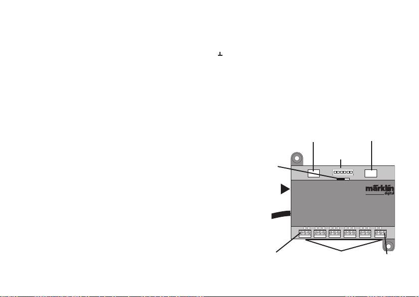
Kontakte (Gleis): 1 – 16
Tasteradressen: 101 – 164
Bus 1: 1001 – 1496 (z.B. 1005 = 1. Modul, Kontakt 5)
Bus 2: 2001 – 2496
Bus 3: 3001 – 3496
Gerätetausch.
Wird ein Gerätetausch notwendig, kann der neue Link S88
auf die bisherige Gerätenummer umgestellt werden. Die
Umstellung erfolgt nach Anmeldung des Link S88 in der CS.
Geben Sie unter „Kennung“ dem neuen S88 die Nummer des
Gerätes, das er ersetzen soll. Danach ist ein Neustart der CS
notwendig, nun funktionieren alle Kontakte wie gewohnt.
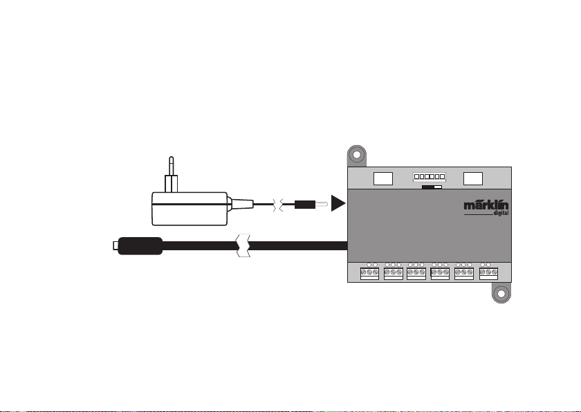
Konfiguration des Link S88
Vor Inbetriebnahme des Link S88 muss dieser zuerst im
Steuergerät konfiguriert werden.
• Mit der CS2 gehen Sie dazu auf Setup/Info. Schalten Sie
hier in den Konfigurationsmodus. Unter „Info“ können Sie
das Gerät auswählen, das Sie bearbeiten wollen. Wählen
Sie hier den neu eingesteckten Link S88
• Mit der CS3 gehen Sie über die Taste „System“ in die
Einstellungen. Wählen Sie hier wiederum „System“. Nun
finden Sie in der linken Spalte eine Taste für den Link S88
Folgende Einstellungen können / müssen vorgenommen
werden:
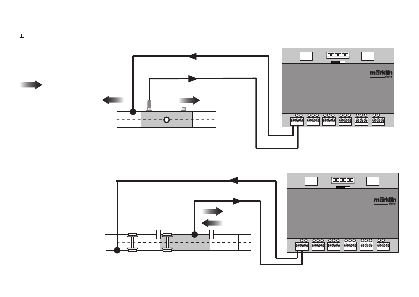
• Auswertung Bus 0 (direkter Bus des Link S88),
Einstellung Einzeln = 16 Melde Kontakte
Einstellung Matrix = bis zu 64 Taster
• Länge Bus 1 – 3
Hier wird eingetragen wieviele S88 an jedem Bus ange-
schlossen sind (max. 31).
• Zykluszeit Bus 1 – 3
Abfragezyklen der S88 Busse in ms (min 10ms - max. 1000 ms)
eintragen (werkseitig 100ms).
• Bitzeit S88
Einstellen Zyklus der Antwort (werkseitig 167µs)
• Zykluszeit (Link S88) Kontakt 1 – 16
Abfragezyklus der Link Kontakte bei Verwendung als Gleis-
kontakt 1 – 16.
• Zykluszeit Tastatur
Abfragezyklus bei Verwendung als Tastatur (werkseitig 67ms).
• Spalten (Ausgang) Tastatur
Eintragen der Spalten (max. 8) der Tastatur Matrix