Esterline Souriau UTS LC Series User manual
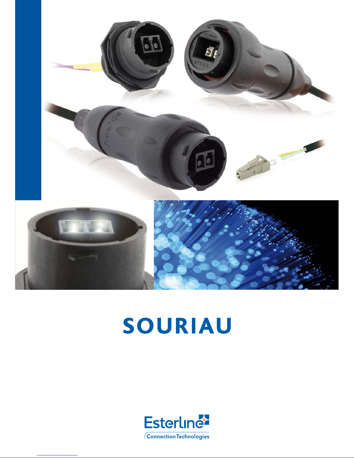
UTS LC Series
BT 304
ASSEMBLY INSTRUCTIONS

3© 2013 SOURIAU
BT304 |UTS LC Series
Contents
Tool & Material .................................................... 4
UTS LC Component details ................................ 5
UTS LC Dimensions ............................................ 5
Assembly Instructions for
UTS1JC18LCN & UTS6JC18LCN ....................... 6
A - Cable preparation ....................................... 6
B - Backshell screwing for UTS1JC18LCN ........ 9
C - Backshell screwing for UTS6JC18LCN ........ 10
Assembly Instructions for UTS718LCN ............... 12
Cleaning & Inspection ........................................ 14
Safety Considerations ......................................... 15

4 SOURIAU 2013 ©
UTS LC Series |BT304
Tool & Material
The following tools and materials are necessary for preparation, assembly, inspection, and maintenance of the
connector and cable assembly. Follow the tool instruction for operation and safety guidelines.
TOOLS
- Cable jacket strip tool
- Aramid Fiber Shears
- Fiber Stripping Tool
- 15 mm U–wrench
- 28 mm U–wrench
- 36.5 mm U–wrench
- Nipper (Oeticker Standard pincers with straight jaws 14100082)
- Heat gun (optional)
MATERIAL
- LC contact: the UTS LC connector range can adapt all kind of LC contact as defined per IEC 61754-20
- Cable: the UTS LC connector range can adapt all type of standard cable from 3 to 6mm outer diameter.
Above these diameter limits some adaptations are necessary
- Suggested glue: LOCTITE®480 PRISM Instant Adhesive
ASSEMBLY INSTRUCTIONS
The assembly should be done in a dust free and dried environment, in accordance with fiber optics good practices.
Make sure that all components are free from contamination.
The assembly instruction is only a guideline and the assembly/manipulations are under the responsibility of the
assembler. Any change of product or material is under the responsibility of the assembler.

5© 2013 SOURIAU
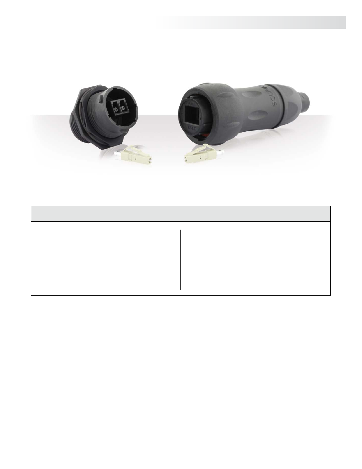
UTS LC Component details
DIMENSIONS (mm)
BT304 |UTS LC Series
UTS1JC18LCN, UTS6JC18LCN, UTS718LCN overview
Sealing cap
Ø 32.5 max
34 max
Ø 42.5 max
24 max
UTS18DCG2
for UTS1JC18LCN & UTS718LCN
UTS618DCG2
for UTS6JC18LCN
Free Hanging Receptacle -UTS1JC18LCN
Ø 6 max
122 max
Ø 42.5 max
Ø 6 max
Plug - UTS6JC18LCN
112 max
Ø 42.5 max
Jam nut receptacle - UTS718LCN
18.5 max 17.5 max
5 max
Ø 45.5 max
Plug
Backshell
Tensile strength
system
Ear
Claw Nut
Gasket
Crimp
support
Receptacles

6 SOURIAU 2013 ©
UTS LC Series |BT304
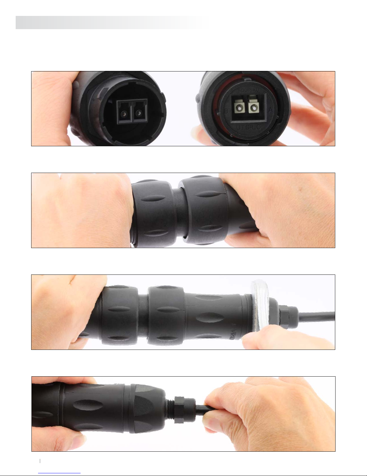
Assembly Instructions for UTS1JC18LCN & UTS6JC18LCN
A - Cable preparation
1. Slide the backshell onto the cable allowing 50 cm at the end of the cable for stripping the cable. Make
sure to orient each component as shown in the UTS LC Component details section.
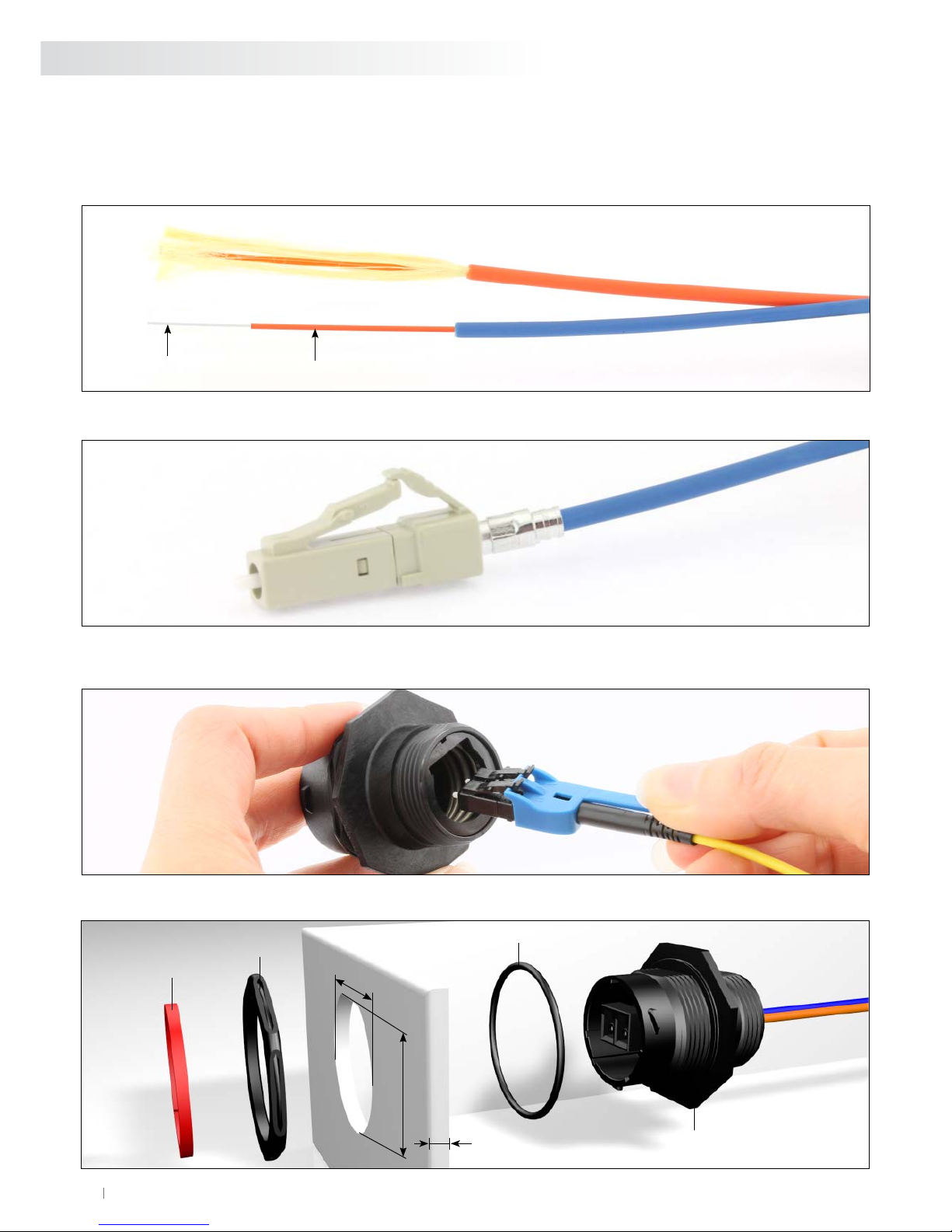
2. Using the cable jacket strip tool, strip the jacket to the dimension given in figure below, exposing the kevlar strength
members and fiber.
3. Using the shears, trim the kevlar strength members to the length given in figure below.
4. Fix the Kevlar using an adhesive tape on the “individual fibers” to facilitate the insertion of the crimp support.
5. Slide the crimp support (large diameter end first) over the fibers and the kevlar strength members until it bottoms on
the cable outer jacket.
6. Separate the kevlar strength members in two groups. Use an adhesive tape to fix the kevlar strength members on the
jacket.
Fiber tube protection: 100±1 mm
Kevlar: 40±1 mm

7© 2013 SOURIAU
BT304 |UTS LC Series
8. Before the instant adhesive begins to harden,quickly slide the ear clamp over the fiber, orient the Clamp
according the picture. Push the strength members back over the clamp until it bottoms on the rear flange of the
support.
7. Apply the instant adhesive on the fiber and cover the crimp support. (e.g. LOCTITE 480 PRISM).
9. Crimp the both ear of the Clamp using the Nipper. Remove the kevlar strength members using using the shears.
Check the good crimping by pulling manually.
11. Strip the fiber buffer according to your LC supplier recommendations and make sure to reach the final desired
lengths for the individual fibers as described on the pictures below.
Bare fiber Fiber buffer
8 SOURIAU 2013 ©
UTS LC Series |BT304
Assembly Instructions for UTS1JC18LCN & UTS6JC18LCN (suite)
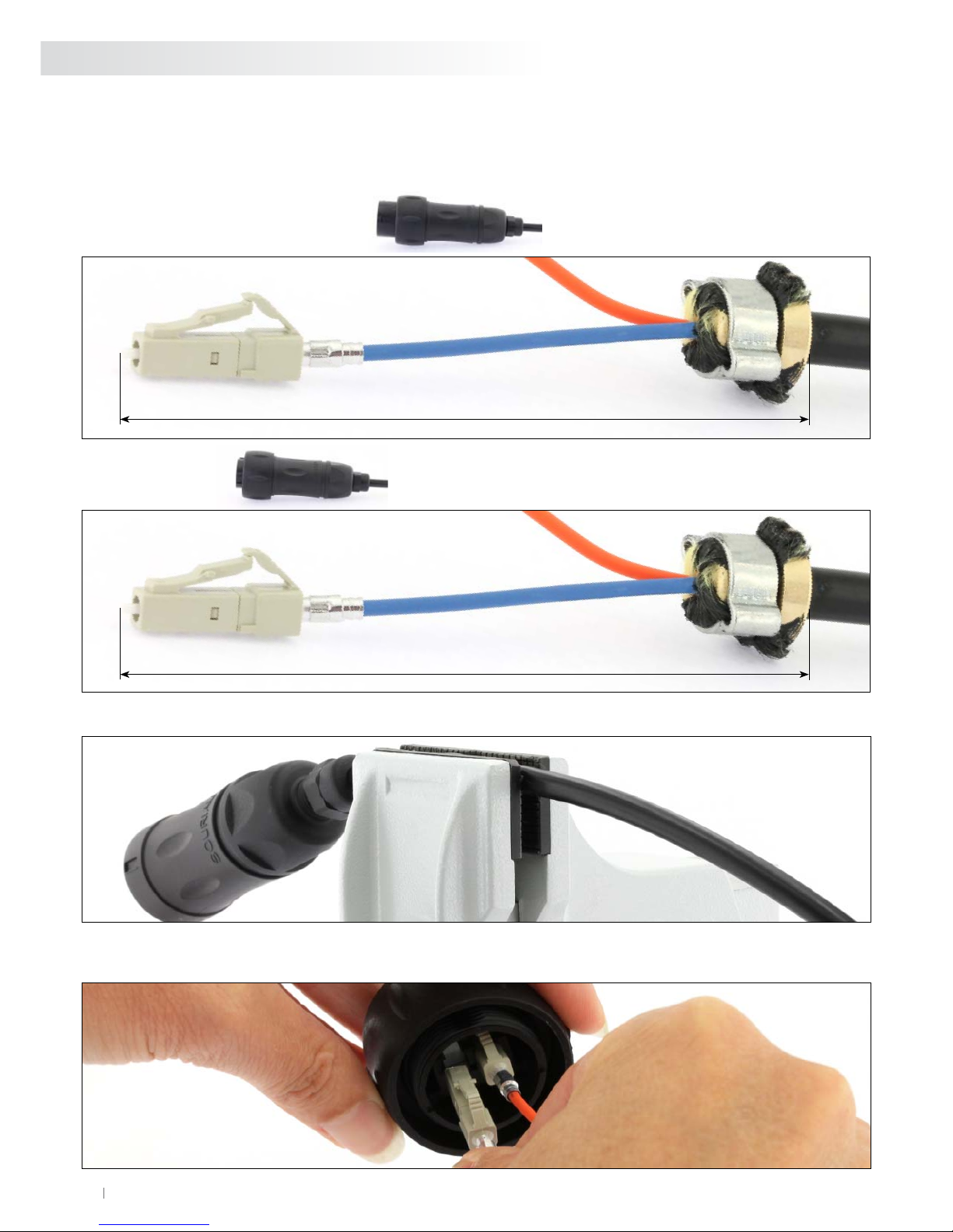
12. Terminate the LC contact on the fiber according to your supplier instruction for gluing, cliving and polishing.
13. Fix the cable in a tool to avoid the rotation.
14. Plug the two LC: Make sure that each LC contact is in the right cavity A or B.
You need to hear a “CLICK”.
Free hanging receptacle UTS1JC18LCN
Free hanging receptacle UTS1JC18LCN: 94±0.2 mm
Plug UTS6JC18LCN: 84±0.2 mm
Plug UTS6JC18LCN
9© 2013 SOURIAU
BT304 |UTS LC Series
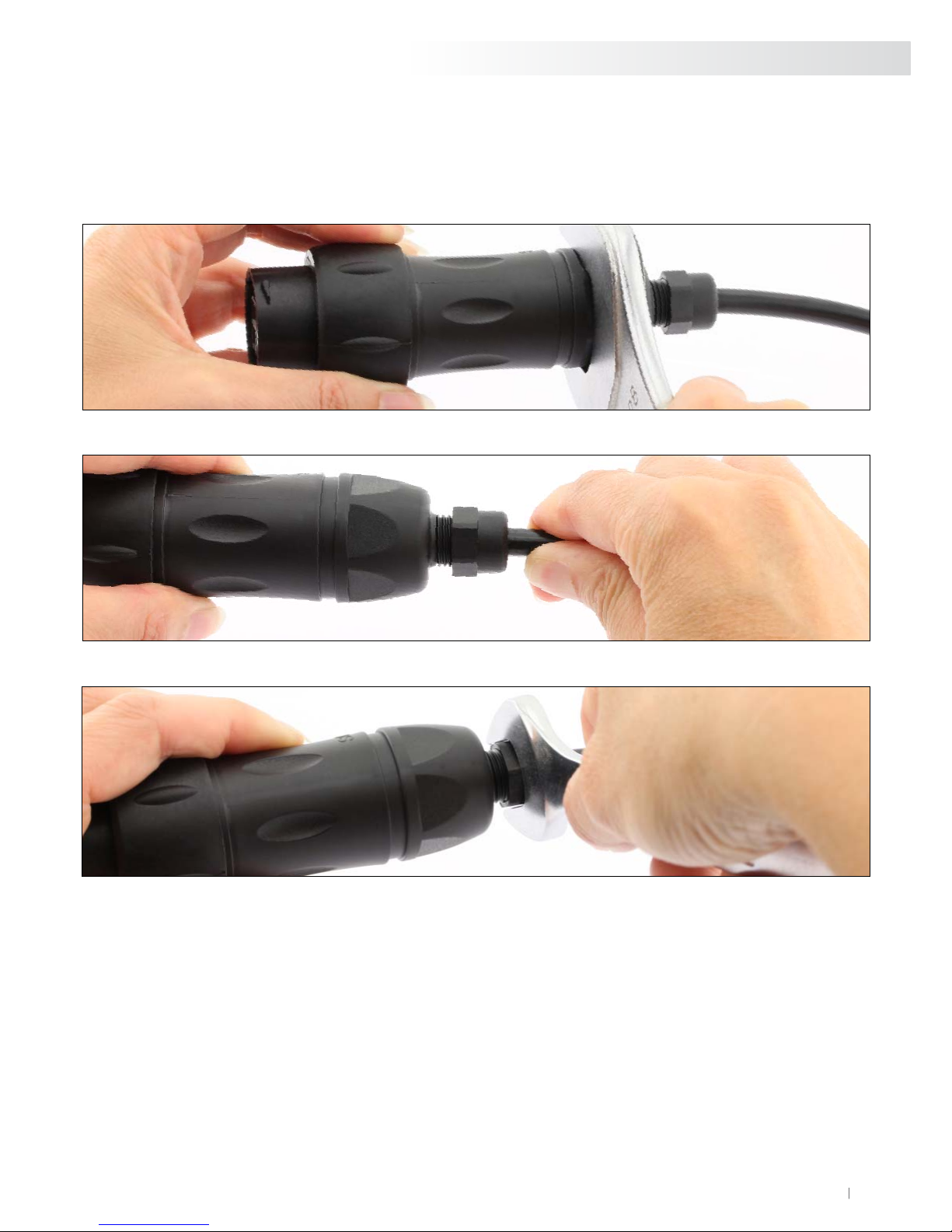
B - Backshell screwing for UTS1JC18LCN
1. Slide the blackshell and screw it using a 28 mm U-wrench. Tightened the backshell with a 4 Nm torque.
2. Control: Pull on the cable to ensure that the retention system bottoms in the backshell.
3. Screw the head nut using a 15 mm U-wrench. Tightened the head nut with a 2 Nm torque.
10 SOURIAU 2013 ©
UTS LC Series |BT304
C - Backshell screwing for UTS6JC18LCN
1. You need a receptacle counter-part. Orient the polarization keys before you start mating the connectors.
2. Coupling plug with receptacle
3. Slide the blackshell and screw it using a 28 mm U-wrench. Tightened the backshell with a 4 Nm torque.
4. Control: Pull on the cable to ensure that the retention system bottoms in the backshell.

11© 2013 SOURIAU
BT304 |UTS LC Series
Recommendation
Use the caps, UTS618DCG2 for plug or UTS18DCG2 for receptacle to protect the LC contacts from surrouding
contamination.
You need to hear a “CLICK”.
5. Screw the head nut using a 15 mm U-wrench. Tightened the head nut with a 2 Nm torque.
12 SOURIAU 2013 ©
UTS LC Series |BT304
Assembly Instructions for UTS718LCN
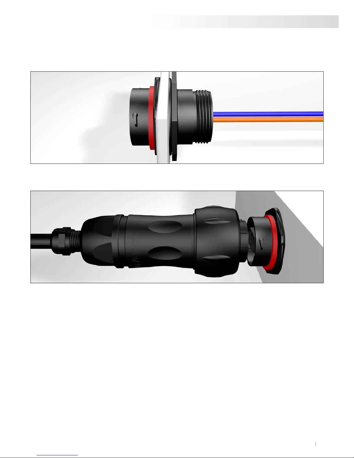
4. Seat o-ring, place receptacle in the panel cut-out.
O-ring
UTS718LCN
Jam nut
Panel thickness:
3.2mm max
30.35 mm
31.85 mm
Optional
coding ring
1. Strip the fiber buffer according to your LC supplier recommendations and make sure to reach the final desired lengths
for the individual fibers as described on the pictures below.
Bare fiber Fiber buffer
2. Terminate the LC contact on the fiber according to your supplier instruction for gluing, cliving and polishing.
3. Plug the two LC in the receptacle. Make sure that each LC contact is in the right cavity A or B.
You need to hear a “CLICK”.
13© 2013 SOURIAU
5. Tightened the jam nut with a torque of 5 Nm, using a 36.5 mm U- wrench.
6. Coupling.
BT304 |UTS LC Series
14 SOURIAU 2013 ©
UTS LC Series |BT304
Cleaning & Inspection
Cleaning and visual inspection of a termini endface is part of the good practices for fiber optics.
This is necessary to ensure the good optical performances of an LC contact inside a UTS LC connector.
Please note that most of the standard inspection and cleaning tool on the market can be used for maintenance of an LC
contact mounted in an UTS LC connector.
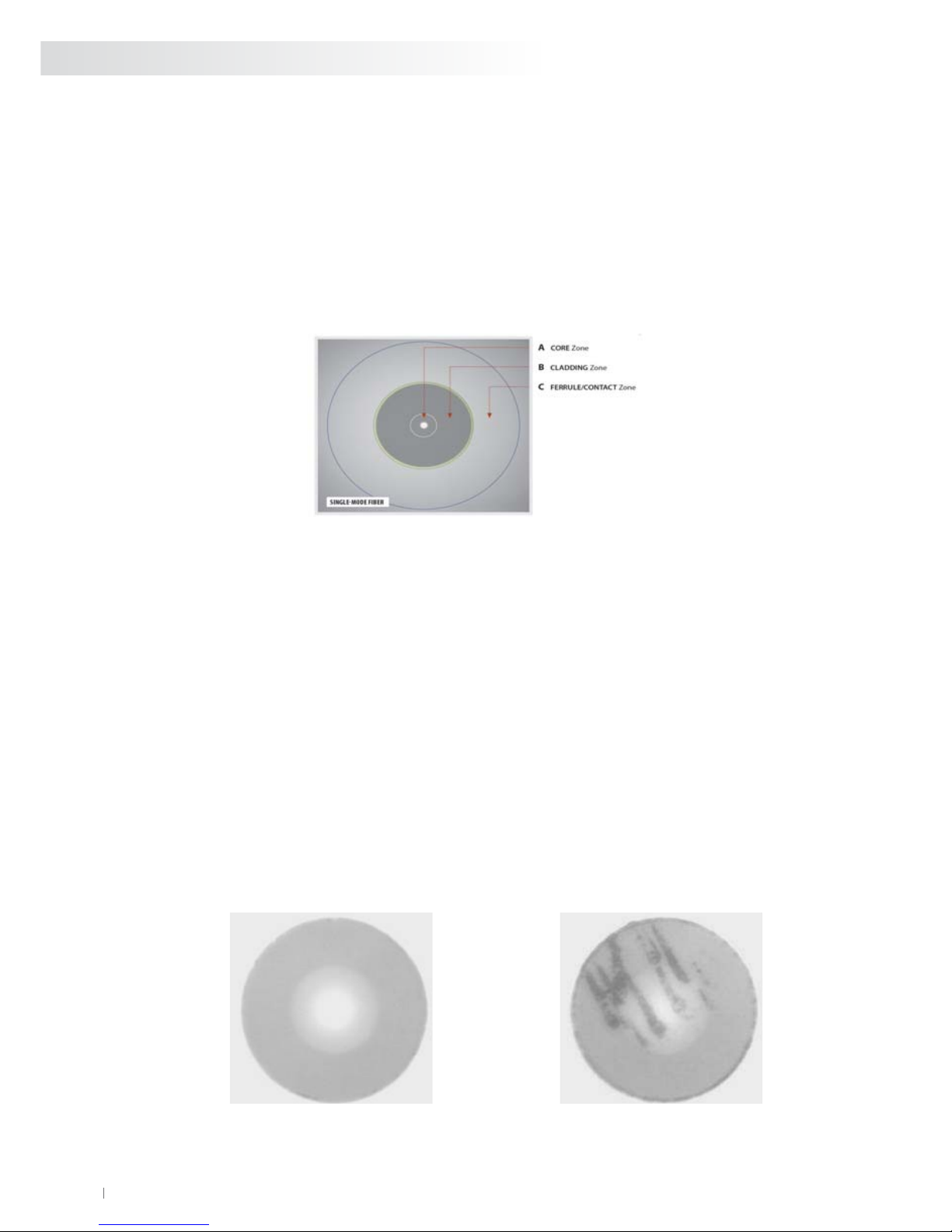
1 Inspection
A- Use a fiber optic video probe (magnification X200 minimum) to inspect the termini endface for contamination,
chips, pits, scratches and shatters in the core and in the inner of the cladding (see figure below).
2 Cleaning
A- Use a lint free tip moistened with 99% reagent grade isopropyl alcohol or optical quality cleaning fluid to clean
the termini endface. Always wipe in one direction, not back and forth.
B- Dry the termini endface with a dry tip.
C- Re-inspect the termini endface with a fiber optic video probe (Magnification x200 minimum) and verify that
the contamination has been removed.
D- If the contamination is still present then repeat step A & B.
E- If after repeated attempts, the contamination is still present and cannot be removed like minor scratches, chips
or pits then re-polish the optical contact (refer to the LC supplier instruction).
B- If dirt, debris or other surface contamination is identified then clean (see below).
E.g. Magnification X 400 of two multimode fibers
For more details, please refer to the acceptance criteria and cleaning procedures defined by IEC for multimode or
singlemode connector termini endface
Clean and good termini endface Contaminated or scratched termini endface

15© 2013 SOURIAU
Safety Considerations
Safety glasses
A- Safety glasses to protect your eyes from accidental injury are strongly recommended when handling chemicals and
cutting fibers. Pieces of glass fiber are very sharp and can damage the cornea of the eye.
B- Glue
Glue may cause eye and skin irritation. Avoid contact with eyes, skin or clothing. Avoid prolonged or repeated
breathing of vapor. Use with adequate ventilation.
C- Fiber Precautions
Cleaved glass fibers are very sharp and can pierce the skin easily. Do not let cut pieces of fiber stick to your clothing or
drop in the work area where they can cause injury later. Use tweezers to pick up cut or broken pieces of the glass fibers
and place them in a debris container. Keep your work area clean.
D- Laser Precautions.
Laser light is invisible and can damage your eyes. Never look into the end of a fiber which may have a laser coupled
to the opposite end.
BT304 |UTS LC Series

INDUTSLCBT01 © Copyright SOURIAU 2013- All information in this document presents only general particulars and shall not form part of any contract. All rights reserved to SOURIAU for changes without prior notification or public announcement. Any duplication is prohibited, unless approved in writing.
www.souriau-industrial.com

Mouser Electronics
Authorized Distributor
Click to View Pricing, Inventory, Delivery & Lifecycle Information:
Souriau:
UTS718LCN UTS6JC18LCN UTS1JC18LCN
This manual suits for next models
4
Table of contents
Other Esterline Cables And Connectors manuals


