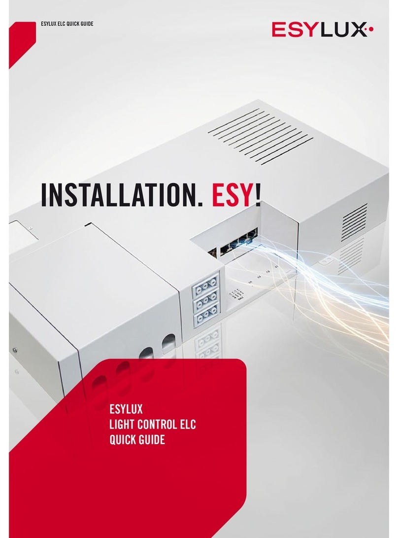
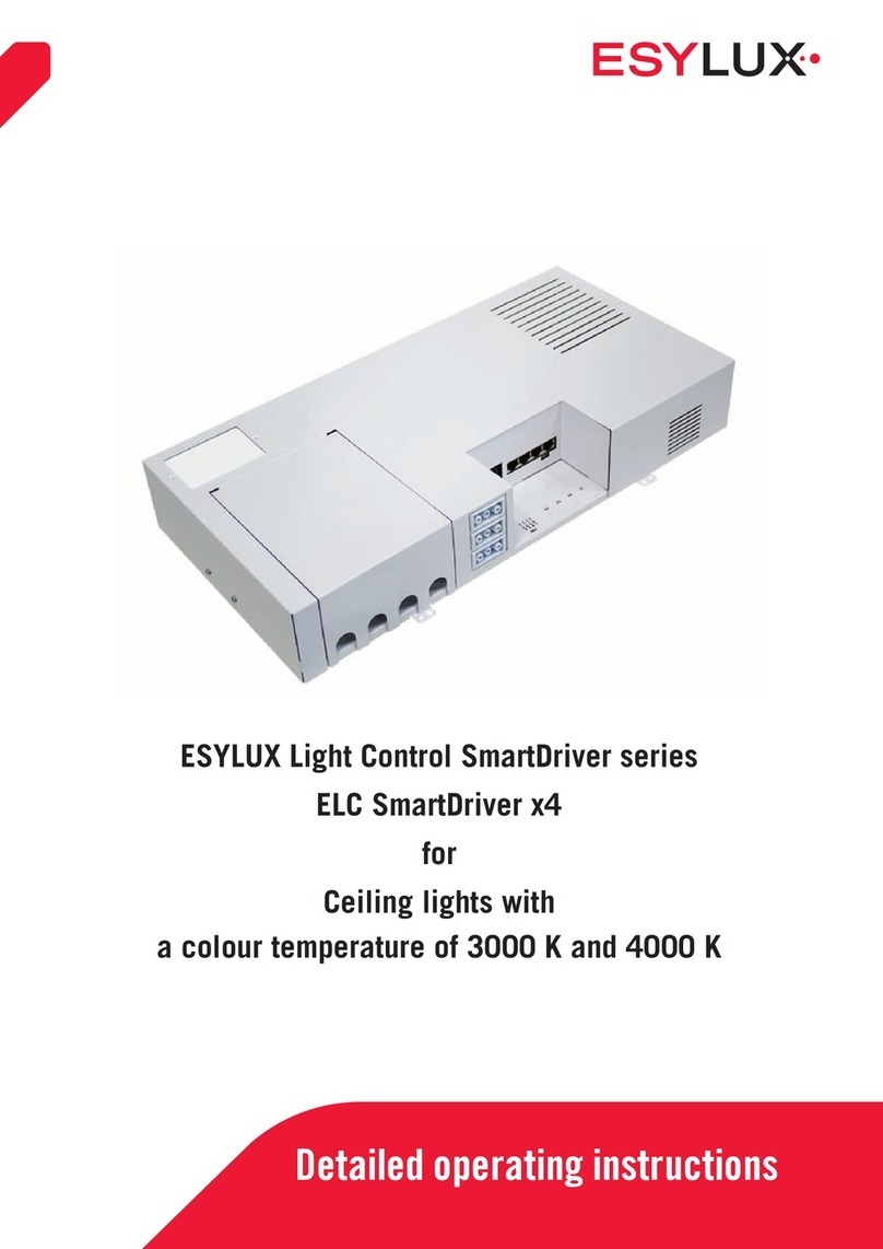
ESYLUX SmartDriver Series User manual

1
Detailed operating instructions
ESYLUX Light Control SmartDriver series
ELC SmartDriver TW x4
ELC SmartDriver TW x6
ELC SmartDriver TW x
for
Ceiling lights with tunable white
Colour temperature 2700 to 6500 K

GB
1 / 112
© ESYLUX GmbH
An der Strusbek 40, 22926 Ahrensburg, Germany
Details may be subject to change.
Copying is only permitted with the written consent of
ESYLUX GmbH. This includes translation into other
languages and reuse of content for other purposes.
Version Date Comment
BA01249803 02/05/2018 4. edition
Doc. no. BA012498_03

Table of contents
GB
Doc. no. BA012498_03
2 / 112
Table of contents
1 Information about the document ...............................................................................6
1.1 Introduction......................................................................................... 6
1.2 Highlighted information within the text .................................................. 6
1.3 Manufacturer address ........................................................................... 6
1.4 Productidentication ........................................................................... 7
1.5 Structure of these instructions............................................................... 7
1.6 Warnings ............................................................................................. 8
2 Basic safety information ..........................................................................................9
2.1 Intended use ....................................................................................... 9
2.2 Liability and damages........................................................................... 9
2.3 Safety instructions ............................................................................... 9
3 Product description ...............................................................................................10
3.1 Equipment ........................................................................................ 10
3.2 Functions .......................................................................................... 10
3.3 Dimensions diagrams.......................................................................... 12
3.3.1 Dimensions ............................................................................ 12
4 Installation and connection.................................................................................... 12
4.1 Installation ........................................................................................ 12
4.2 Connecting the SmartDriver ................................................................ 14
4.3 Connecting devices to the SmartDriver ................................................. 16
4.3.1 Overview: Connectable devices ................................................. 16
4.3.2 Connections............................................................................ 17
4.3.3 Connecting the presence detector ............................................. 17
4.3.4 Connecting CELINE/NOVA lights............................................... 18
4.3.5 Connecting DALI switch devices ............................................... 19
4.3.6 Connecting DALI buttons ......................................................... 21
4.3.7 Connecting to KNX bus............................................................ 22
4.3.8 Connecting SmartDrivers in parallel .......................................... 23
4.3.9 Alternative: External DALI power supply .................................... 27
4.4 Connecting lighting groups using the ELC bus....................................... 29
4.4.1 Differences between DALI and ELC connections......................... 30
4.4.2 Establishing an ELC bus connection ........................................ 31
4.5 Warm-up phase.................................................................................. 33
4.6 Factory settings.................................................................................. 34
4.7 Initial steps ....................................................................................... 34

Table of contents
GB
Doc. no. BA012498_03
3 / 112
5 Overview of operating modes .................................................................................35
5.1 Sequence of the operating modes ........................................................ 35
5.2 Manually triggered operating modes ..................................................... 37
5.3 Operating modes and detected movements ........................................... 39
6 Setting via remote control...................................................................................... 40
6.1 Selecting X-Light Control TW remote control ......................................... 41
6.2 X-Light Control TW menu layout .......................................................... 41
7 The <Functions> remote control menu ...................................................................44
7.1 Channels 1 and 2............................................................................... 44
7.1.1 On/Off.................................................................................... 44
7.1.2 Start/stop dimming.................................................................. 45
7.1.3 Luminousefciency ................................................................ 46
7.1.4 CCT value............................................................................... 46
7.1.5 CCT dim start/stop .................................................................. 47
7.2 All channels ...................................................................................... 48
7.3 Call scene ......................................................................................... 48
7.4 Store scene ....................................................................................... 49
7.5 DALI switch....................................................................................... 49
7.5.1 DS1/DS2 on ........................................................................... 49
7.5.2 DS1/DS2 off........................................................................... 50
7.6 Reset ................................................................................................ 50
7.7 Test start/stop .................................................................................... 51
7.8 KNX Prog. On/Off ............................................................................... 51
8 The remote control menu <Programming> .............................................................52
8.1 Activate/deactivate programming mode ................................................ 52
8.2 Calibration......................................................................................... 52
8.3 All channels ...................................................................................... 54
8.3.1 Store brightness...................................................................... 54
8.3.2 Light set value ........................................................................ 56
8.3.3 Off delay time......................................................................... 57
8.3.4 Off warning............................................................................. 57
8.3.5 Orientation light...................................................................... 58
8.3.6 Orient. time mode ................................................................... 59
8.3.7 Orient. light in min.................................................................. 60
8.3.8 Orient. light from h/Orient. light to h ......................................... 61
8.3.9 Fully automatic....................................................................... 62
8.3.10 Semi-automatic ...................................................................... 62
8.4 SymbiLogic™ .................................................................................... 63
8.5 Channel Map ..................................................................................... 64
8.6 DALI map.......................................................................................... 65
8.7 DALI switch....................................................................................... 66

Table of contents
GB
Doc. no. BA012498_03
4 / 112
8.7.1 DS1/DS2 connected ................................................................ 66
8.7.2 DS1/DS2 not connected .......................................................... 66
8.7.3 DS1/DS2 switch-off delay ........................................................ 67
8.7.4 DS1/DS2 mode....................................................................... 67
8.8 Scene editor ...................................................................................... 68
8.9 Calendar ........................................................................................... 69
8.10 Factory reset...................................................................................... 71
8.11 Reset editor....................................................................................... 72
8.12 Sensitivity ......................................................................................... 72
8.13 Detector LED on/Detector LED off........................................................ 73
8.14 Light value off/light value on ............................................................... 73
8.15 Detector factory reset ......................................................................... 74
8.16 Detector Light Factor.......................................................................... 75
9 Operation via Bluetooth App...................................................................................76
9.1 SmartDriver with Bluetooth ................................................................. 76
9.2 The ESYLUX LIGHT CONTROL app...................................................... 76
9.2.1 Using the app ......................................................................... 76
9.2.2 Differences between the Android and iOS app............................ 77
9.3 Setting up a Bluetooth connection ....................................................... 78
10 The app main menu ............................................................................................... 80
11 The app menu <Manual>....................................................................................... 81
11.1 Switching channels on and off............................................................. 81
11.2 Changing the brightness and colour temperature ................................... 83
11.3 Back to normal operation mode ........................................................... 84
11.4 Switching the switching channels on and off......................................... 84
12 Theappmenu<Proles>.......................................................................................85
13 The app menu <Settings>...................................................................................... 87
13.1 The General submenu......................................................................... 88
13.1.1 Setting the date and time ........................................................ 88
13.1.2 Adjusting the radio range ......................................................... 89
13.1.3 Adjusting automatic mode........................................................ 90
13.1.4 Setting the switch-off delay time .............................................. 91
13.1.5 Setting the off warning ............................................................ 92
13.1.6 Changing orientation light brightness ........................................ 93
13.1.7 Setting orientation light afterglow ............................................. 93
13.1.8 Resetting the SmartDriver to factory settings.............................. 94
13.2 Light management submenu ............................................................... 95
13.2.1 Constant light management, light target value and light measure-
ment 96

Table of contents
GB
Doc. no. BA012498_03
5 / 112
13.2.2Conguringvialightsensors..................................................... 96
13.2.3 Manual settings ...................................................................... 99
13.3 Switching channels submenu ............................................................ 101
13.3.1 Switching channel - Active .................................................... 101
13.3.2 Switching channel - Operating mode ...................................... 102
13.3.3 Switching channel - Delay time ............................................. 102
13.4 SymbiLogic submenu ....................................................................... 103
13.5 DALI mapping submenu ................................................................... 104
14 Settings via the 230 V button............................................................................... 105
14.1 Button S1 ...................................................................................... 105
14.1.1 Switching the lighting on/off .................................................. 105
14.1.2 Dim lighting ......................................................................... 105
14.2 Button S2 ....................................................................................... 106
14.2.1 Accessing scenes .................................................................. 106
14.2.2 Dimming the colour temperature ............................................ 106
15 Settings via DALI button....................................................................................... 107
15.1 List of DALI commands .................................................................... 107
16 Maintenance....................................................................................................... 109
16.1 Cleaning.......................................................................................... 109
16.2 Troubleshooting................................................................................ 110
17 Technical data .................................................................................................... 111
18 Disposal .............................................................................................................112
19 EC-declaration of conformity................................................................................112

Information about the document
Doc. no. BA012498_03
6 / 112
GB
1 Information about the document
1.1 Introduction
These operating instructions contain detailed information about device
functions and the processes for commissioning and assembling the speci-
eddevices.
This document is also available online at www.esylux.com and can be print-
ed in A4 format.
When you are reading the document on screen, you can use the following
functions:
• Linked table of contents: Clicking on the chapter title opens the cor-
responding chapter.
• List of bookmarks: All chapters can be accessed from the list of
bookmarks. You can usually open the list of bookmarks in the PDF
software by clicking the symbol .
• Linkedreferences:Youcanmovetospeciedlocationsbyclickingon
the link. Many PDF programs highlight such links when you hover the
mouse cursor over the link, or they change the shape of the mouse
cursor. For example: .
Please read the operating instructions carefully and note all safety informa-
tion and warnings.
1.2 Highlighted information within the text
To make these user instructions easier to read, certain information is high-
lighted using different formatting. The meaning of this formatting is ex-
plained below:
< > indicates remote control menu items
Grey indicates a function
indicates a call for user action
is used to highlight results of actions
indicates important and useful information
warns of high voltage
1.3 Manufacturer address
ESYLUX GmbH
An der Strusbek 40
22926 Ahrensburg, Germany
Website: www.esylux.com
Email: [email protected]
Navigating
on screen

Information about the document
Doc. no. BA012498_03
7 / 112
GB
1.4 Productidentication
These instructions apply to the following products:
Item number Item designation
EC10430572 ELC SmartDriver TW x4
EC10430596 ELC SmartDriver TW x4 BT
EC10430589 ELC SmartDriver TW x4 KNX
EC10431005 ELC SmartDriver TW x6
EC10431012 ELC SmartDriver TW x6 BT
EC10431029 ELC SmartDriver TW x6 KNX
EC10431036 ELC SmartDriver TW x8
EC10431043 ELC SmartDriver TW x8 BT
EC10431050 ELC SmartDriver TW x8 KNX
The item designation contains important information about the product:
Item designation
information Meaning
ELC SmartDriver Series name of the ESYLUX Light Control
SmartDriver
TW Tunable White: For lights with an adjusta-
ble colour temperature of 2700–6500 K
x4/x6/x8
Number of lights that can be connected via
RJ-45
BT Can be operated via Bluetooth and app
KNX KNX connection
1.5 Structure of these instructions
Chapters 2 to 4 include technical data and all information regarding safe
installation and operation of the ESYLUX ELC SmartDrivers. The SmartDriv-
er is also referred to as the Light Control Box in these instructions.
An overview of functions is provided in Chapter 3.2. Chapter 5 explains
the operating modes. Understanding the sequence of the operating modes
makesiteasiertocongurethedevice.
Each Light Control Box can be operated via remote control and buttons.
Remote control makes it much more convenient to choose the settings and
many settings are only possible via remote control. An ESYLUX DALI pres-
DALI presence
detector
required

Information about the document
Doc. no. BA012498_03
8 / 112
GB
ence detector must be connected to the Box to ensure the Light Control Box
can receive remote control signals (see Chapter 4.3.3).
Chapters 6 to 8 cover the remote control menu. The remote control groups
the functions according to whether they directly control the Light Control
BoxorareusedtoconguretheLightControlBox:
• Direct control: The corresponding functions are found in the remote
control sub-menu <Functions>.
Direct controls adjust the lights to more unusual situations for which
the basic settings are not ideal. Such adjustments to the programmed
sequence, for example, changing brightness, are temporary. The ad-
justments are not saved.
• Conguration:Otherthanafewexceptions,thebasicsettingsthatare
sufcientformostsituationsaremadeintheremotecontrolmenu
<Programs>.
The Light Control Box with a Bluetooth radio module provides an additional
and particularly convenient operating option: Users of Bluetooth-capable
devices such as smartphones or tablets can control the Light Control Box
via the free ESYLUX LIGHT CONTROL app. Operation via app is explained
starting from Chapter 9.
1.6 Warnings
Warnings are listed at the start of the relevant chapter if a hazardous situa-
tion is likely to occur.
The preceding signal words have the following meanings:
DANGER!
This signal word denotes a hazard involving a high level of risk. Failure to ob-
serve the warning will lead to serious or fatal injury.
WARNING!
This signal word denotes a hazard involving a moderate level of risk. Failure to
observe the warning may lead to serious or fatal injury.
CAUTION!
This signal word denotes a hazard involving a low level of risk. Failure to ob-
serve the warning may lead to minor or moderate injury.
CAUTION!
This signal word warns against situations that could lead to instances of proper-
ty damage if the information is not observed.
Remote control
Operation via
app

Basic safety information
Doc. no. BA012498_03
9 / 112
GB
2 Basic safety information
2.1 Intended use
The ESYLUX Light Control Box (tunable white) may only be used for the
following purposes:
• Installation in indoor areas as an operating device for the ESYLUX
CELINE Satellite (tunable white) and NOVA Slave (tunable white) re-
cessed surface-mounted ceiling lights.
• Each Light Control Box can control and power lights that are con-
nected via RJ-45. The number of lights that can be connected varies
depending on the model.
• Light Control Boxes are suitable for power supply routing. The maxi-
mum total current of the mains terminal is 10 A.
2.2 Liability and damages
Thedevicemustnotbechanged,modiedorpainted—doingsowillvoid
any warranty claims.
The manufacturer will not accept any liability for instances of personal inju-
ry or property damage caused by improper use.
Check the product for damage after unpacking. If the device is damaged in
any way, return it to the relevant place of sale.
2.3 Safety instructions
Electrical devices connected to a 230-V mains supply may only be assem-
bled and commissioned by electrical installation technicians or trained
electricians,takingcountry-specicregulationsintoaccount.
DANGER!
Risk of fatal injury from electric shock!
Thefollowingvesafetyrulesmustalwaysbeobserved:
1. Disconnect the power supply
2. Secure the power supply from being switched on again
3. Check that the relevant components have been de-energised
4. Set up the earthing and short-circuiting mechanisms as required
5. Cover or isolate neighbouring live parts
Specialist per-
sonnel!

Product description
Doc. no. BA012498_03
10 / 112
GB
PLEASE NOTE:
Reversing the polarity can cause the DALI devices to malfunction!
NotetheDALIspecications(IEC62386).
Useacable(notsupplied)thatcomplieswiththeDALIspecications
(IEC 62386) for all DALI connections.
3 Product description
3.1 Equipment
The ESYLUX Light Control Box is designed for indoor use as an operating
device for the ESYLUX CELINE Satellite (tunable white) and ESYLUX NOVA
Slave (tunable white) recessed surface-mounted ceiling lights.
Each Light Control Box has a DALI connector, RJ-45 connectors and RJ-11
connectors.
The Light Control Box is also available with the following additional equip-
ment:
• Bluetooth operating interface
• KNX module
Details of the item numbers of the Light Control Box variants can be found
on page 7.
The RJ-45 interfaces and DALI interfaces can be used to connect the fol-
lowing devices:
• RJ-45: CELINE Satellite lights and NOVA Slave lights. The lights are
powered and controlled by the ESYLUX Light Control Box
• DALI: an additional Light Control Box, DALI presence detectors, DALI
switches
• RJ-11: This connection is used to connect lighting groups via the ELC
bus (see chapter 4.4 on page 29).
For more information regarding connection options, see page 16.
Included in delivery: ELC SmartDriver, DALI-C0 connection cable, ELC bus
connection cable, wired terminal for connection to DALI C1/C2.
3.2 Functions
To enable the Light Control Box to perform its functions, a DALI presence
detector (not supplied) must be connected to the Light Control Box.
The Light Control Box controls the connected lighting. Constant lighting
control occurs only if the presence detector detects the presence of people
Connectable
devices
Prerequisite:
DALI detector
Constant light
control

Product description
Doc. no. BA012498_03
11 / 112
GB
or animals and is dependent on the ambient lighting.
With the DALI system (Digital Addressable Lighting Interface), the Light
Control Box receives the control telegrams via the electronic ballasts, and
simultaneously controls all lights connected in the DALI group.
The table below provides a list of the Light Control Box functions. This over-
view is intended to serve as a decision-making aid for electrical installation
techniciansanduserswhenconguringthesettingsatalaterpoint.
Most settings can be only be adjusted via remote control or app.
Function Benet
Dimming Adjusts the illumination level.
Set colour tempera-
ture
Sets the connected lights to a warmer or colder
light.
Constant light
control
Consistent lighting conditions by automatically
adjusting the illumination level to the ambient light
levels when people are detected.
SymbiLogic™
Automatic control of the colour temperature and
brightness throughout the day according to the natu-
ral change in light in a selected location.
Light measurement The presence detector light sensor or an additional
light sensor measures the ambient light level.
Switch-off delay time Sets the off-delay following the last detected pres-
ence.
Off warning Indicates that the off delay time has elapsed.
Orientation light Activates or deactivates subtle lighting of rooms and
corridors following expiry of the off delay time.
Orientation light
duration
Sets the duration of the orientation light in hours or
toaspecictime.
Fully automatic
mode
Automatic control of the lighting when presence is
detected.
Semi-automatic
mode
Automatic control of the lighting when presence is
detected must be activated manually via an external
button.
Light scenes Selectfromfourcongurablelightcongurationsfor
room lighting.
For detailed function descriptions, refer to the chapters on opera-
tion via remote control or app.
DALI
Overview of
functions

Installation and connection
Doc. no. BA012498_03
12 / 112
GB
3.3 Dimensions diagrams
3.3.1 Dimensions
236 mm
474 mm
264 mm
132
mm
75 mm
SmartDriver TW
x8
x4
x6
SmartDriver TW
4 Installation and connection
4.1 Installation
The Light Control Box is intended for use in wall or ceiling mounting. To
ensure that the device is adequately ventilated, the following clearances to
walls and ceilings must be maintained:
• Clearance to the sides of the device: at least 5 cm.
• Clearance to the top or bottom (in case of ceiling mounting): at least
10 cm.

Installation and connection
Doc. no. BA012498_03
13 / 112
GB
Min. 50 mm
Min. 50 mm
Min. 50 mm
Min. 50 mm
Min. 100 mm
Min. 100 mm
Illustration: Clearances to walls and ceilings
Installation:
Drillfourxingholes.
Screw the Light Control Box securely into place.
Ceiling and wall mounting

Installation and connection
Doc. no. BA012498_03
14 / 112
GB
4.2 Connecting the SmartDriver
Unscrew the cover to access the connection terminals.
1.
21
Connection terminal for buttons S1/S2
2. Mains terminal
DANGER!
Risk of fatal injury from electric shock!
Switch off the power to the cable.
Check that the cable is de-energised.
Connection to the power supply:
Connect the Box to the mains terminal and to the earth conductor
terminal as shown in the wiring diagram.
1. Button S1
2. Button S2
3. Phase 230 V AC
4. Neutral conductor
5. Earth conductor

Installation and connection
Doc. no. BA012498_03
15 / 112
GB
Wiring diagram:
L
N
PE
S1 S2
X
XS2
S1 L L
C0- C0-
C0+ C0+
N N
1. 2. 3. 4. 5.

Installation and connection
Doc. no. BA012498_03
16 / 112
GB
4.3 Connecting devices to the SmartDriver
4.3.1 Overview: Connectable devices
The Light Control Box is designed to be connected to lights and DALI devic-
es via the following connections:
• RJ-45 sockets for connecting CELINE Satellites or NOVA slave lights
• DALI connections for connecting presence detectors, DALI switches
and other Light Control Boxes (DALI C0), and DALI devices (DALI
C1/C2)
The RJ-11 sockets are for connecting lighting groups. See image
page 30.
DS1
DS2
DALI
DALI C1 - C2 DALI C0
RJ-45
S1/S
2
max. 2 x 25
DALI
Overview: Connection possibilities

Installation and connection
Doc. no. BA012498_03
17 / 112
GB
4.3.2 Connections
1.
5
4
21 3
6
KNX connection (for ELC SmartDriver KNX model only)
2. Mains terminal with DALI C0 connections
3. DALI C1-C4 connection socket
4. RJ-45 socketsforconnectingspeciedESYLUX
lights
5. USB connection, exclusively for service purposes
6. DALI C0 connection sockets
7.
8
7
9
”DALI Power” switch for DALI bus voltage supply (see chapter
4.3.8.1 on page 24)
8. “ELCbusconguration”switch. Switch position “ON”: Only devic-
es at the beginning and end of an ELC bus connection.
9. RJ-11 sockets for connecting via the ELC bus (see chapter 4.4 on
page 29).
4.3.3 Connecting the presence detector
To enable the Light Control Box to control the lighting according to your
preferences, you need to connect a DALI presence detector. The following
ESYLUX DALI ceiling-mounted presence detectors are suitable:
• PD-C360i/8 ELC (order number EP10427602)
DALI
presence
detector

Installation and connection
Doc. no. BA012498_03
18 / 112
GB
• PD-C360i/24 ELC (order number EP10427619)
Thesepresencedetectorshavea360°eldofdetection.Thedetectorsalso
measure brightness and receive the infrared signals from the remote con-
trol. A DALI cable is included in the delivery of the detector with the right
jack for connecting to the Light Control Box.
Proceed as follows to connect the presence detector:
Use the cable included with the presence detector to connect the
Light Control Box and the presence detector.
ESYLUX
PD-C360i/8 ELC
PD-C360i/24 ELC
C0
C0
SENSOR
4.3.4 Connecting CELINE/NOVA lights
ESYLUX ELC SmartDriver TW ESYLUX NOVA Slave / CELINE Satellite
Tunable White
RJ-45
CW WW
RJ-45
CW WW
RJ-45
CW WW
RJ-45
CW WW
RJ-45
CW WW CW WW
C2 C1
RJ-45
CW WW CW WW
C2 C1
You can connect the following ESYLUX lights to the RJ-45 sockets on the
Light Control Box:
• CELINE Satellite tunable white (colour temperature of 2700–6500 K).
RJ-45 jack

Installation and connection
Doc. no. BA012498_03
19 / 112
GB
• NOVA Slave tunable white (colour temperature of 2700–6500 K).
Each tunable white light is powered by the Light Control Box via two con-
nection cables. You must always insert the cable in sockets with the same
label (“ww”/”cw”).
The Light Control Box (tunable white) has two channels (C1, C2) for lighting
control.
Any up-to-date network cable, type Cat5 or higher, can be used as
the RJ-45 patch cable.
NOTE!
Do not connect cables to incorrect sockets!
Connecting cables to incorrect sockets may lead to incorrect light colours.
Note the maximum cable length!
The RJ-45 connection cable must not exceed 10 metres.
Connection to be used for ESYLUX lights only!
OnlythespeciedESYLUXlightsmaybeconnectedtotheRJ-45interfac-
es. Other equipment such as Internet routers or lights designed to be pow-
ered via a LAN cable (power over Ethernet) could be irreparably damaged by
connecting them to the RJ-45 jacks.
4.3.5 Connecting DALI switch devices
DALI switch devices can also be connected to the DALI interfaces C1 and
C2. DALI switch devices can be used to connect non-DALI-compatible
equipment such as fans or screen controllers.
The DALI switch devices are available as accessories. By default, the model
SW DALI Full Automation (item no. EP10427473) is set to fully automatic
with a off delay time of 30 minutes. By default, the model SW DALI Semi
Automation (item no. EP10427480) is set to semi-automatic with a off
delay time of six minutes. You can change these factory settings on both
models via the remote control. For more information about these devices,
see our website www.esylux.com.
A maximum of two DALI groups can be connected to the DALI interfaces C1
and C2. A maximum of 25 DALI devices can be connected in each group,
with the groups being powered via the DALI bus. The parameters are auto-
matically applied to the electronic ballasts via broadcast.
The DALI interfaces are numerically assigned to the lighting channels. For
example, DALI interface C2 corresponds to the lighting channel C2.
You can change the assignment of the DALI interfaces DALI C1
and C2 to the lighting channels C1 and C2 (RJ-45 connections).
See Chapter “DALI Map” page 65.
This manual suits for next models
3
Table of contents
Other ESYLUX Controllers manuals
Popular Controllers manuals by other brands
Panasonic
Panasonic EYFRZ01 operating instructions

National Instruments
National Instruments 73 Series manual
METRON
METRON FD4 manual
Milwaukee
Milwaukee MC740 user manual

Desert Aire
Desert Aire CM3510 Series Installation and operation manual

Superior Electric
Superior Electric STABILINE WHR5206 instructions
DALCNET
DALCNET DSL-5A-SPI-KIT Device manual

Bender
Bender CC611 manual

AXIOMATIC
AXIOMATIC AX141120 user manual
GE
GE EntelliPro ES Series Installation and instruction manual
Murphy
Murphy Automatic Engine Controller EA150 owner's manual
I2R Tech Lighting Solutions
I2R Tech Lighting Solutions Moving Head Controller 2.0 user manual
