ESYLUX CDSi-A/N User manual

Congratulations on your purchase of this high-quality ESYLUX product. To
ensure proper operation, please read these user instructions carefully and
keep them for future reference.
1 • SAFETY INSTRUCTIONS
CAUTION: Work on the 230 V power system must be carried out
by authorised personnel only with due regard to the applicable
installation regulations. Switch off the power supply before
installing the system.
Use this product only as intended (as described in the user
instructions). Changes or modifications to the product or
painting it will result in loss of warranty. You should check the
device for damage immediately after unpacking it. If there is
any damage, you should not install the device under any
circumstances.
If you suspect that safe operation of the device cannot be
guaranteed, you should turn the device off immediately and
make sure that it cannot be operated unintentionally.
2 • DESCRIPTION
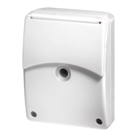
The ESYLUX CDSi-A/N and CDSi-A/N16AX twilight switches
are surface-mounted switches for the automatic switching of
lighting systems (fig. 1).
A light sensor detects the ambient lighting level. If the level falls
below the preset light value (lux), the twilight switch
automatically turns on the connected lighting; it turns the
lighting off again when the ambient lighting level exceeds the
threshold value. Also programmable by remote control;
therefore fast and precise setting of various parameters with no
need for tools or a ladder.
3 • INSTALLATION / ASSEMBLY / CONNECTION
Switch off the power supply. Only install the twilight switch on
even, vertical, north-facing surfaces (house walls) and, if at all
possible, not in direct sunlight. Also ensure that the twilight
switch will not be affected by the connected lighting (fig. 1).
Unscrew the housing cover and install the holder on the
surface, making sure that the line entrances are at the bottom.
The line entrance must be wired in a permanent, waterproof
connection. The module can be taken out to make it easier to
thread and connect the wire (fig. 3).
Connect the twilight switch according to the wiring diagram
(fig. 2.1/2.2). There is a 1.5 mm2jumper between L (power
supply) and L (floating contact).
This jumper must be removed if the relay contact is to be used
for extra-low voltage (only affects the CDSi-A/N model).
Screw the housing cover back on. The switching point is preset
to a realistic value.
• •CDSi-A/N
• •CDSi-A/N16AX
www.esylux.com
GB TWILIGHT SWITCH
4 • START-UP AND SETTING
• Connect the power supply
• LED Display
Green LED flashes slowly (f = 0.5 Hz) = day operation
(Ambient lighting is higher than the default light value);
connected lighting is OFF.
Red LED flashes slowly (f = 0.5 Hz) = night operation
(Ambient lighting is lower than the default light value);
connected lighting is ON.
Red LED lights up (60 sec) = light switch-on value has been reached;
connected lighting remains OFF as the 60 second delay is
enabled – then change-over into night operation.
Green LED lights up (60 sec) = light switch-off value has been reached;
connected lighting remains ON as the 60 second delay is
enabled – then change-over into day operation.
Red LED flashes rapidly (f = 4 Hz) = “12 h ON” function is enabled via
remote control;
connected lighting is switched on for a duration of 12 hours.
Green LED flashes rapidly (f = 4 Hz) = “12 h OFF” function is enabled via
remote control;
connected lighting is switched off for a duration of 12 hours.
4.1 Settings via manual adjuster
The required light value (approx. 1 - 300 lux) can be set via the
potentiometer (fig. 4). The LED acts as a setting aid (fig. 4).
Recommended setting procedure: When the required switch-on time is
reached (e.g. twilight), turn the potentiometer slowly towards the
“moon symbol” until the red LED light up.
The set light value now corresponds to the actual ambient
lighting level and the twilight switch is now adjusted.
When carrying out this process, ensure that the light sensor is
not shielded by your hand or body.
NOTE: Please ensure that the connected lighting only switches on or
off after a time delay of 60 seconds once the LED lights up.
The 60 second delay means that unintended switching, caused,
for example, by passing car headlights or a dark cloud, is avoided.
4.2 Setting by remote control (available as accessory)
The remote control Mobil-RCi-M (fig. 5) means that the settings
can be easily programmed without needing to climb a ladder or
use any tools.
The manual adjuster setting will be overwritten when using the
remote control. All settings programmed by remote control are
permanently stored in the memory (EEPROM) and will not be lost
in the event of a power failure.
TWILIGHT SWITCH
GB
FIG. 1 FIG. 3
FIG. 2.1 • CDSi-A/N FIG. 4
FIG. 2.2 • CDSi-A/N16AX
NOTE: The stored remote control settings (lux values) will be
deleted if the manual adjuster (fig. 4) is adjusted by 45° within
2 seconds; in this case the value of the adjuster will be reactivated.
For optimum reception, when programming the settings, point
the remote control at the twilight switch. Please note that if the
sun shines directly on the sensor, the standard detection range
of approx. 6 m may be dramatically reduced owing to the
sun's infrared rays.
Button Functional description
Signal reception:
The yellow LED flashes for 2 seconds the signal
transmitted by the remote control has been
acknowledged.
The current ambient lighting level (within the range
1 - 1000 lux) can be input as a switching value.
Input current light conditions as switch-on value
(when the lighting is off)
Input method:
When the required ambient lighting level is
reached, press the button.
Acknowledgement of the received signal: Connected
lighting will switch ON and yellow LED will flash
slowly. When the input process is successfully
completed the lighting will switch OFF.
Note: The current ambient lighting level cannot
be input as a switch-on value if this level is too
bright (> 1000 lux) or too dark (< 1 lux). In
this situation the highest (1000 lux) or lowest
(1 lux) possible value will be stored as the
switch-on value.
Continuous lighting 12 h ON/OFF
If the lighting is OFF, it can be switched on at
any time for a duration of 12 hours by pressing
the button.
Press this button again to switch the
12 hour-lighting off.
Once the 12 hours have expired, the detector
switches back to the corresponding set
operating mode.
Reset
This interrupts the “Continuous lighting 12 h
ON/OFF” feature and returns to the
“twilight switch” operating mode.
ON/OFF
12h
RESET
FIG. 6
96
76 52 15
7
44
80
7
RESET
ON/OFF
12h
PE N N L L L L´
N
ON/OFF
12h
FIG. 5
PE N N L L´
N
CDSi-A/N
IP 54
PE N LLNLL´
230 V ~ 50 Hz
2300 W / 10 A (cos ϕ= 1)
1150 VA / 5 A (cos ϕ= 0,5)
12 V / 24 V DC / 5 A
Dry Contact
Art.-Nr.:ED10016608
CDSi-A/N
230 V ~ 50 Hz
2300 W / 10 A (cos ϕ= 1)
1150 VA / 5 A (cos ϕ= 0,5)
12 V / 24 V DC / 5 A
Dry Contact
Art.-Nr.:ED10016608
IP 54
PE N LLNLL´
3a

Technical and design features may be subject to change.
TECHNICAL DATA
MAINS VOLTAGE 230 V ~ 50 Hz
1 - 300 Lux via manual adjuster
1 - 1000 Lux by remote control
Changing the switching hysteresis via jumper
approx. 60 sec
230 V ~ 50 Hz
2300 W / 10 A (cos ϕ= 1)
1150 VA / 5 A (cos ϕ= 0,5)
12 V / 24 V DC / 5 A,
No Safety Extra Low Voltage
floating, 1 contact
-25° C … +55° C
IP 54
II
TÜV
white, similar to RAL 9010
brown, similar to RAL 8017
TWILIGHT VALUE
SWITCH-ON AND
SWITCH-OFF DELAY
SWITCHING CAPACITY
CDSi-A/N
230 V ~ 50 Hz 16 AX
3600 W / 16 A (cos ϕ= 1)
3600 VA / 16 A (cos ϕ= 0,5)
SWITCHING CAPACITY
CDSi-A/N16AX
SWITCHING OUTPUT/
SWITCH CONTACT
OPERATING
TEMPERATURE RANGE
PROTECTION TYPE
PROTECTION CLASS
TEST SYMBOL
COLOUR
5 • CHANGING THE SWITCHING THRESHOLD
In the case of custom applications, there is the option of
changing the threshold value (switching hysteresis between
switch-on and switch-off value) via a jumper.
a) The jumper is connected as default:
• For example: set light value 3 lux = switch-on value;
the switch-off value is then approx. 8 - 9 lux.
b) If the jumper is removed:
• For example: set light value 3 lux = switch-on value;
the switch-off value is then approx. 4 - 5 lux.
To remove the jumper, disconnect the power supply and take
out the module (fig. 3). The jumper is located on the circuit
board (fig. 3a).
6 • PRACTICAL ADVICE
Lighting flashes ON/OFF
The twilight switch is affected by its own lighting.
NOTE: Ensure that the light sensor is not exposed to any
extraneous light, e.g. neighbours’ lights. The twilight switch
must not be installed beneath the light.
7 • ESYLUX WARRANTY
ESYLUX products are tested in accordance with applicable
regulations and manufactured with the utmost care. The
duration of the warranty is based on statutory guidelines. The
warranty can only be honoured if the appliance is sent back
with the receipt, unchanged, packed and with sufficient
postage to ESYLUX GmbH or to the relevant distributor in your
country. (Visit www.esylux.com for a complete overview.)
Please include a brief written description of the fault with any
device you send back.If the warranty claim proves justified,
ESYLUX GmbH will, within a reasonable period, either repair
the device or replace it. If a claim is unfounded (e.g. because
the warranty has expired or the fault is not covered by the
warranty), then ESYLUX GmbH will attempt to repair the device
for you in a cost-effective manner. The warranty does not apply
to natural wear and tear, changes caused by environmental
factors or damage in transit, nor to damage caused as a result
of failure to follow the installation or user instructions. Any
batteries or bulbs supplied with the device are not covered by
the warranty.
ESYLUX GmbH shall not be liable for any indirect,
consequential or financial losses.
ESYLUX GmbH
Postfach 1834, 22908 Ahrensburg/Germany
Internet: www.esylux.com
WA 04/2009
This manual suits for next models
1
Other ESYLUX Switch manuals


