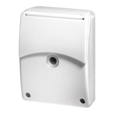
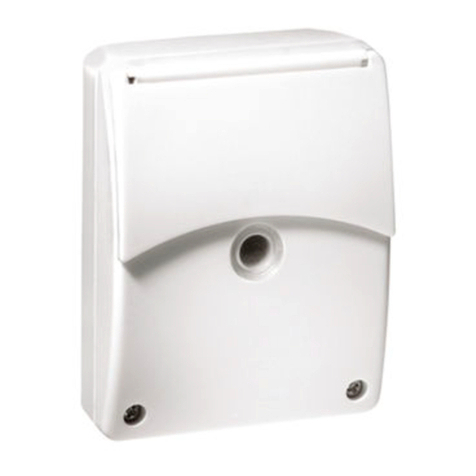
ESYLUX DEFENSOR TS User manual

OPERATING INSTRUCTION
DEFENSOR
• TS
• TS T
OUTDOOR AUTOMATION IGB
TWILIGHT SWITCH

GB
© ESYLUX GmbH
An der Strusbek 40, 22926 Ahrensburg, Germany
Details may be subject to change.
Copying is only permitted with the written consent of ESYLUX GmbH. This includes translation into
other languages and reuse of content for other purposes.
MA01709900
2 / 34
Version Date Comment
MA01709900 14/04/2020 First edition

GB
MA01709900
3 / 34
Table of contents
1. Information about the document 5
1.1 Introduction ....................................................................................................5
1.2 Highlighted information within the text................................................................5
1.3 Manufacturer address .......................................................................................6
1.4 Productidentication .......................................................................................6
1.5 Warnings.........................................................................................................7
2. Basic safety information 8
2.1 Safety instructions ...........................................................................................8
2.2 Intended use ...................................................................................................8
2.3 Liability and damages.......................................................................................9
3. Product description 9
3.1 Introduction ....................................................................................................9
3.2 Included in delivery ........................................................................................ 10
3.3 Settings – an overview .................................................................................... 10
3.4 Mechanical set-up.......................................................................................... 11
3.5 Rating label...................................................................................................12
3.6 Dimension drawing.........................................................................................12
4. Installation and connection 13
4.1 Installation .................................................................................................... 13
4.2 Connection.................................................................................................... 17
4.2.1 Standard operation............................................................................. 17
4.2.2 Standard operation with additional control using a push button................18
4.2.3 Parallel connection.............................................................................18
5. Initial operation 19
5.1 Warm-up phase .............................................................................................19
5.2 Default settings .............................................................................................19
6. ESY Control app and ESY-Pen 20
6.1 Operating principle.........................................................................................20
6.2 ESY Control app ............................................................................................21
6.3 Connecting the ESY-Pen to the ESY Control app ................................................22

GB
MA01709900
4 / 34
7. Settings with the ESY Control app 23
7.1 Temporary settings.........................................................................................23
7.1.1 Light on / off .....................................................................................23
7.1.2 4 h / 12 h light on / off.......................................................................24
7.1.3 Reset to automatic mode ....................................................................24
7.2 Permanent settings ........................................................................................24
7.2.1 Set time and date ..............................................................................25
7.2.2 Operating mode .................................................................................25
7.2.3 Brightness switching value...................................................................28
7.2.4 Reset to default settings .....................................................................28
7.2.5 Test mode .........................................................................................29
7.2.6 Password protection ...........................................................................29
8. Manual control via push button 30
9. Maintenance 31
9.1 Cleaning ....................................................................................................... 31
9.2 Troubleshooting .............................................................................................32
10. Technical data 32
11. Disposal 34
12. EU Declaration of Conformity 34
13. ESYLUX manufacturer's guarantee 34

GB
5 / 34
MA01709900
Information about the document
1. Information about the document
1.1 Introduction
These operating instructions contain detailed information about the
installation,commissioningandcongurationofthespecieddevices.
This document is available online on the relevant product web page
at www.esylux.com and can be printed out in A4 format. Please read
the operating instructions carefully and note all safety information and
warnings.
When you are reading the document on screen, you can use the following
functions:
• Linked table of contents: Clicking on the chapter title opens the
corresponding chapter.
• Linked references:Youcannavigatetospeciedlocationsby
clicking on the link .
• List of bookmarks: All chapters can be accessed from the list of
bookmarks inthesoftwareyouusetoviewPDFles.
1.2 Highlighted information within the text
To make these operating instructions easier to read, certain information is
highlighted by different means. The meaning of this formatting is explained
below:
¾ indicates a call for action
9 indicates results of actions
< > indicates menu items of the app
indicates text links
indicates important and useful information
warns of high voltage
Navigating on
screen
Formatting

GB
6 / 34
MA01709900
Information about the document
1.3 Manufacturer address
ESYLUX GmbH
An der Strusbek 40
22926 Ahrensburg I Germany
www.esylux.com
1.4 Product identication
These instructions apply to the following products:
Item number Product name
ED10025471 DEFENSOR TS IR 1C IP55 WH
ED10025464 DEFENSOR TS T IR 1C IP55 WH
Youcanndtheitemnumberandproductnameonthetypeplateofthe
products in chapter "3.5 Rating label" on page 12.
The product name contains important information about the product:
Elements Meaning
DEFENSOR Series
TS Twilight switch
T Time function
IR Remote controllable (infrared)
1C 1 light channel
IP55 Protection type
WH White (housing colour)

GB
7 / 34
MA01709900
Information about the document
1.5 Warnings
Warnings are listed at the start of the relevant chapter if a hazardous
situation is likely to occur.
The preceding signal words have the following meanings:
DANGER!
This signal word denotes a hazard involving a high level of risk. Failure to
observe the warning will lead to serious or fatal injury.
WARNING!
This signal word denotes a hazard involving a moderate level of risk. Failure
to observe the warning may lead to serious or fatal injury.
CAUTION!
This signal word denotes a hazard involving a low level of risk. Failure to
observe the warning may lead to minor or moderate injury.
NOTE!
This signal word warns against situations that could lead to instances of
property damage if the information is not observed.

GB
8 / 34
MA01709900
Basic safety information
2. Basic safety information
2.1 Safety instructions
Electrical devices connected to a 230-V mains voltage must only be
installed and commissioned by electrical installation technicians or trained
electricians,takingcountryspecicregulationsintoaccount.
DANGER!
Risk of fatal injury from electric shock!
¾ Thefollowingvesafetyrulesmustalwaysbeobserved:
1. Disconnect the power supply
2. Secure the power supply from being switched on again
3. Check that the relevant components have been de-energised
4. Set up the earthing and short-circuiting mechanisms as
required
5. Cover or isolate neighbouring live parts
¾ Protect the device with a 10-A circuit breaker.
¾ Protect the circuit with a residual current device (RCD).
¾ Observethecontactopeningwidth(μ=<1.2mm).
2.2 Intended use
The twilight switches in the DEFENSOR series are designed for use in
outdoor areas and automatically control the lighting based on ambient
light conditions. They are suitable for use around the home, and in
gardens, garages or carports.
The switches are designed for wall mounting. Surface mounting or
mounting on inner / outer corners is possible with the appropriate
accessories.
Specialist
personnel
Place of use

GB
9 / 34
MA01709900
Product description
2.3 Liability and damages
Thedevicemustnotbechanged,modiedorpainted–doingsowillvoid
any warranty claims.
The manufacturer will not accept any liability for instances of personal
injury or property damage caused by improper use.
Check the product for damage after unpacking. If the device is damaged in
any way, return it to the relevant place of sale.
3. Product description
3.1 Introduction
The twilight switch automatically controls the lighting based on ambient
lightconditions.Iftheambientlightinglevelfallsbelowthecongured
brightness switching value, the twilight switch switches on the connected
lighting; it switches the lighting off again when the ambient lighting level
exceeds the threshold value.
Main product features:
• Automaticlightcontroldependingontheconguredbrightness
switching value
• The twilight switch is supplied with the default settings
The following table shows an overview of the functions of the devices:
Functions TS TS T
Time-dependent operating modes •
Integrated push button input • •
Zero-cross switching to protect
the relay • •
Password-protected parameterisation • •
Properties
Overview of
features

GB
10 / 34
MA01709900
Product description
Functions TS TS T
High overvoltage protection • •
CongurableviatheESYControlapp
and ESY-Pen • •
3.2 Included in delivery
1 x twilight switch
1 x short instruction
Optional accessories:
ESY-Pen (item no. EP10425356)
Spacer (item no. EM10025426)
Corner bracket (item no. EM10025419)
3.3 Settings – an overview
The twilight switch has no setting elements. All settings can only be
modiedusingtheESYControlappandtheESY-Pen.
Setting options Description
Light on / off Used to manually switch lighting on or off
regardless of ambient light conditions
4 h / 12 h light on / off
Used to manually switch lighting on or off for
4 hours or 12 hours regardless of ambient
light conditions
Reset to automatic mode Used to reset temporary settings
Set time and date Used to set the date and time in order to use
time-dependent functions
Twilight switch
operating mode
Enables light control on the basis of the
brightness switching value
Light on / off
operating mode
Used to manually switch lighting on or off
regardless of ambient light conditions
Accessories
Operation via ESY
Control app with
ESY-Pen

GB
11 / 34
MA01709900
Product description
Setting options Description
Brightness switching value
The lighting is automatically controlled
onthebasisoftheconguredbrightness
switching value
Reset to default settings Used to reset the twilight switch to
default settings
Test mode Checks that the lighting switches on based
on the brightness switching value
Password protection Used to set a password to protect against
unauthorised access
Youcanndacomprehensivedescriptionofthepossiblesettingsin
chapter "7. Settings with the ESY Control app" on page 23.
3.4 Mechanical set-up
1. Sensor inspection window
2. Cover
3. Mounting base with sensor

GB
12 / 34
MA01709900
Product description
3.5 Rating label
1. Product name
2. Item number
3. Technical data
3.6 Dimension drawing
108 mm
92 mm 46 mm

GB
13 / 34
MA01709900
Installation and connection
4. Installation and connection
4.1 Installation
The twilight switch is intended for wall mounting. The twilight switch must
be mounted on a solid, even surface. Surface mounting or mounting on
inner / outer corners is possible with the appropriate accessories.
Wall mounting
The following installation types are possible with accessories:
Wall mounting with spacers in the case of surface-mounted cabling
Installation
type / location

GB
14 / 34
MA01709900
Installation and connection
Mounting on outer corners with a corner bracket
NOTE!
In order to prevent chipping due to bore holes that are at too much of an
angle, observe the positioning of the screws.
Mounting on inner corners with a corner bracket
Installation instructions:
¾ Position the twilight switch in a location that is appropriate for the
spatial conditions and requirements.
¾ Do not expose the twilight switch to direct sunlight.
¾ Ensureconnectedlightingismountedwithsufcientclearance
from the twilight switch to avoid any interference with the light
sensor.
¾ Do not point light sources directly at the twilight switch.

GB
15 / 34
MA01709900
Installation and connection
DANGER!
Risk of fatal injury from electric shock!
¾ Switch of the mains voltage before installing / removing
the detector.
¾ Check that the mains voltage is de-energised.
Installation steps:
¾ Remove the cover from the mounting base. These are connected
via a plug-in connection.
¾ Feed the cable into the detector and install the mounting base in
the required position.
The distances between the screw holes are compatible with
those of the RC series of outdoor motion detectors from ESYLUX.
The distances between the screw holes are suitable for
conventionalrecessedboxes(60mm).

GB
16 / 34
MA01709900
Installation and connection
Afterconnectingthetwilightswitch,tthecoveronthemountingbase
as follows:
¾ Press the cover onto the mounting base.
9 A"click"noiseatthetopandbottomconrmsthattheyhavebeen
properlyxedtogether.
¾ Then tighten the screws.

GB
17 / 34
MA01709900
Installation and connection
4.2 Connection
DANGER!
Risk of fatal injury from electric shock!
¾ Switch of the mains voltage before connecting the product.
¾ Check that the mains voltage is de-energised.
Proceed as follows to connect the twilight switch:
¾ Observe the following circuit diagrams and terminal assignments.
LExternal conductor, 230 V ~
L’ Switched external conductor 230 V ~
NNeutral conductor
SPush button
Aseparateterminalisalsoavailabletoloopthroughorxtheearth
conductor.
Earth conductor
4.2.1 Standard operation
Terminal
assignment

GB
18 / 34
MA01709900
Installation and connection
4.2.2 Standard operation with additional control using a push button
Youcanndacomprehensivedescriptionofthisinchapter"8. Manual
control via push button" on page 30.
4.2.3 Parallel connection
Up to ten twilight switches can be connected in parallel.

GB
19 / 34
MA01709900
Initial operation
5. Initial operation
5.1 Warm-up phase
The twilight switch initiates a warm-up phase each time the mains voltage
is connected.
¾ Connect the mains voltage.
9 Awarm-upphaseofapprox.45secondsisinitiated.
9 During this time, the lighting is switched on.
9 Whenthetwilightswitchiscommissionedforthersttime,the
detectorLEDashesblue–red–redalternately.
9 Thewarm-upphaseisoverwhenthegreendetectorLEDbriey
ashesthreetimesafterthisandthelightingswitchesoffagain.
Ifindividualsettingshavealreadybeenconguredonthetwilight
switch,thedetectorLEDashesblue–redalternatelyduringthe
warm-up phase.
5.2 Default settings
The twilight switch is equipped with default settings. It is ready for
operation after the warm-up phase and operates in accordance with the
default settings:
TS
Operating mode Twilight switch
Brightnessswitchingvalue 20lx
Test mode Off
Password 0000
TS T
Operating mode Twilight switch
Brightnessswitchingvalue 20lx
Test mode Off
Timeanddate notdened
Adjustment of the clock to summer / winter time On
Password 0000
Warm-up phase

GB
20 / 34
MA01709900
ESY Control app and ESY-Pen
Thesettingscanbere-conguredorcustomisedatanytime
using the ESY Control app via the ESY-Pen; see chapter
"7. Settings with the ESY Control app" on page 23.
All of the twilight switches from the DEFENSOR series are also equipped
with overvoltage protection to prevent irreparable damage due to lightning
strikesortemporaryoverloadingofpowersupplysystems(surge2kV,burst
4kV).
6. ESY Control app and ESY-Pen
6.1 Operating principle
ParameterscanonlybeconguredusingtheESYControlappwiththe
ESY-Pen (item no. EP10425356).
First, the parameters are changed in the ESY Control app. Then the
ESY-Pen serves as a bridge to transmit the Bluetooth commands from the
mobile device to the twilight switch using infrared technology.
As the infrared interface is located in the head of the ESY-Pen, the
following must be taken into account with regards to communication
between the ESY-Pen and the twilight switch:
¾ When programming, always direct the head of the ESY-Pen
towards the twilight switch.
Direct sunlight can reduce the standard range
ofapprox.8m.
This is due to the effect of the sun's infrared radiation
Parametrisation
This manual suits for next models
3
Table of contents
Other ESYLUX Switch manuals
Popular Switch manuals by other brands
Cisco
Cisco Nexus 9364C-GX Hardware installation guide
Rowley
Rowley AUTOMATION RTMWCR1C quick start guide
Austin Hughes Electronics
Austin Hughes Electronics CyberView DB-15-IP802H user manual
Transition Networks
Transition Networks SM24TAT4GPA user manual
Siemens
Siemens SIMATIC NET RUGGEDCOM RS8000A installation guide
Cisco
Cisco Meraki MS125 Series installation guide
