Etabeta electronics JNR 90L BEAM G User manual
The following points have to be considered during the inspection:
1) All screws for installing the devices or parts of the device have to be tightly connected
and must not be corroded.
2) There must not be any deformations on the housing, color lenses, fixations and
installation spots (ceiling, suspension, trussing).
3) Mechanically moved parts must not show any traces of wearing and must not rotate with
unbalances.
4) The electric power supply cables must not show any damage, material fatigue or sediments.
Further instructions depending on the installation spot and usage have to be adhered by a
skilled installer and any safety problems have to be removed.
In order to make the lights in good condition and extend the life time, we suggest a regular
cleaning to the lights.
1) Clean the inside and outside lens each week to avoid the weakneness of the lights due to
accumulation of dust.
2) Clean the fan each week.
3) A detailed electric check by approved electrical engineer each three month, make sure
that the circuit contacts are in good condition, prevent the poor contact of circuit from
overheating.
We recommend a frequent cleaning of the device. Please use a moist, lint- free cloth. Never
use alcohol or solvents.
There are no serviceable parts inside the device. Please refer to the instructions under
“Installation instructions”.
Should you need any spare parts, please order genuine parts from your local dealer.
MAINTENANCE AND CLEANING
10
Disconnect from mains before starting maintenance operation.
CAUTION
JNR 90L BEAM G
JNR-8124G
PR LIGHTING LTD.
http://www.pr-lighting.com
1582 Xingye Avenue, Nancun Panyu
Guangzhou, 511442 China
TEL: +86-20-3995 2888
.01.
If the device has been exposed to temperature changes due to environmental changes,
do not switch it on immediately. The arising condensation could damage the device.
Leave the device switched off until it has reached room temperature.
This device falls under protection-class I. Therefore it is essential that the device be
earthed.
The electric connection must carry out by qualified person.
The device shall only be used with rate voltage and frequency.
Make sure that the available voltage is not higher than stated at the end of this manual.
Make sure the power cord is never crimped or damaged by sharp edges. If this would
be the case, replacement of the cable must be done by an authorized dealer.
Always disconnect from the mains, when the device is not in use or before cleaning it.
Only handle the power cord by the plug. Never pull out the plug by tugging the power
cord.
During initial start-up some smoke or smell may arise. This is a normal process and
does not necessarily mean that the device is defective, it should decrease gradually.
Please don't project the beam onto combustible substances.
Fixtures cannot be installed on combustible substances, keep more than 50cm
distance with wall for smooth air flow, so there should be no shelter for fans and
ventilation for heat radiation.
If the external flexible cable or cord of this luminaire is damaged, it shall be exclusively
replaced by the manufacturer or his service agent or a similar qualified person in order
to avoid a hazard.
This device has left the factory in perfect condition. In order to maintain this
condition and to ensure a safe operation, it is absolutely necessary for the user to
follow the safety instructions and warning notes written in this user manual.
CAU T I O N
Becareful with your operations.With a dangerous voltage you cansuffer a
dangerous electric shock when touching wires!
IMPORTANT
Damages caused by the disregard of this user manual are not subject to warranty.
The dealer will not accept liability for any resulting defects or problems.
SAFETY INSTRUCTIONS
1
.10.
Gobo 5 shake slow to fast
Gobo 6 shake slow to fast
Gobo 7 shake slow to fast
Gobo 8 shake slow to fast
Gobo 9 shake slow to fast
Gobo 10 shake slow to fast
Gobo 11 shake slow to fast
Gobo 12 shake slow to fast
Gobo 13 shake slow to fast
Gobo 14 shake slow to fast
Gobo 15 shake slow to fast
Gobo 16 shake slow to fast
Gobo 17 shake slow to fast
Rot. gobo wheel cont. rotation slow to fast
Shutter closed
Shutter open
Strobe effect slow to fast
Shutter open
Pulse-effect in sequences slow to fast
Shutter open
Random strobe effect slow to fast
Shutter open
Dimmer 0%...100%
In(near)to out(far)
OFF
ON
Rotating from slow to fast
Max to min speed
Blackout by movement
Blackout by all wheel changing
No function
No function
No function
No function
No function
All motor reset
Scan motor reset
Colors motor reset
Gobo motor reset
Shutter&Dimmer motor reset
Other motor reset
Internal program 1
Internal program 2
Internal program 3
Internal program 4
Internal program 5
Internal program 6
Internal program 7
Internal sound program 1
122-129
130-137
138-145
146-153
154-161
162-169
170-177
178-185
186-193
194-201
202-209
210-217
218-225
226-255
0-31
32-63
64-95
96-127
128-159
160-191
192-223
224-255
0-255
0-255
0-5
6-127
128-255
0-225
226-235
236-245
246-255
0-19
20-29
30-39
40-79
80-84
85-87
88-90
91-93
94-96
97-99
100-119
120-139
140-159
160-179
180-199
200-219
220-239
240-255
Shutter
Dimmer
Focus
Prism
Speed
pan/tilt
Special
function
5
6
7
8
10
9
7
8
9
10
12
11
.02.
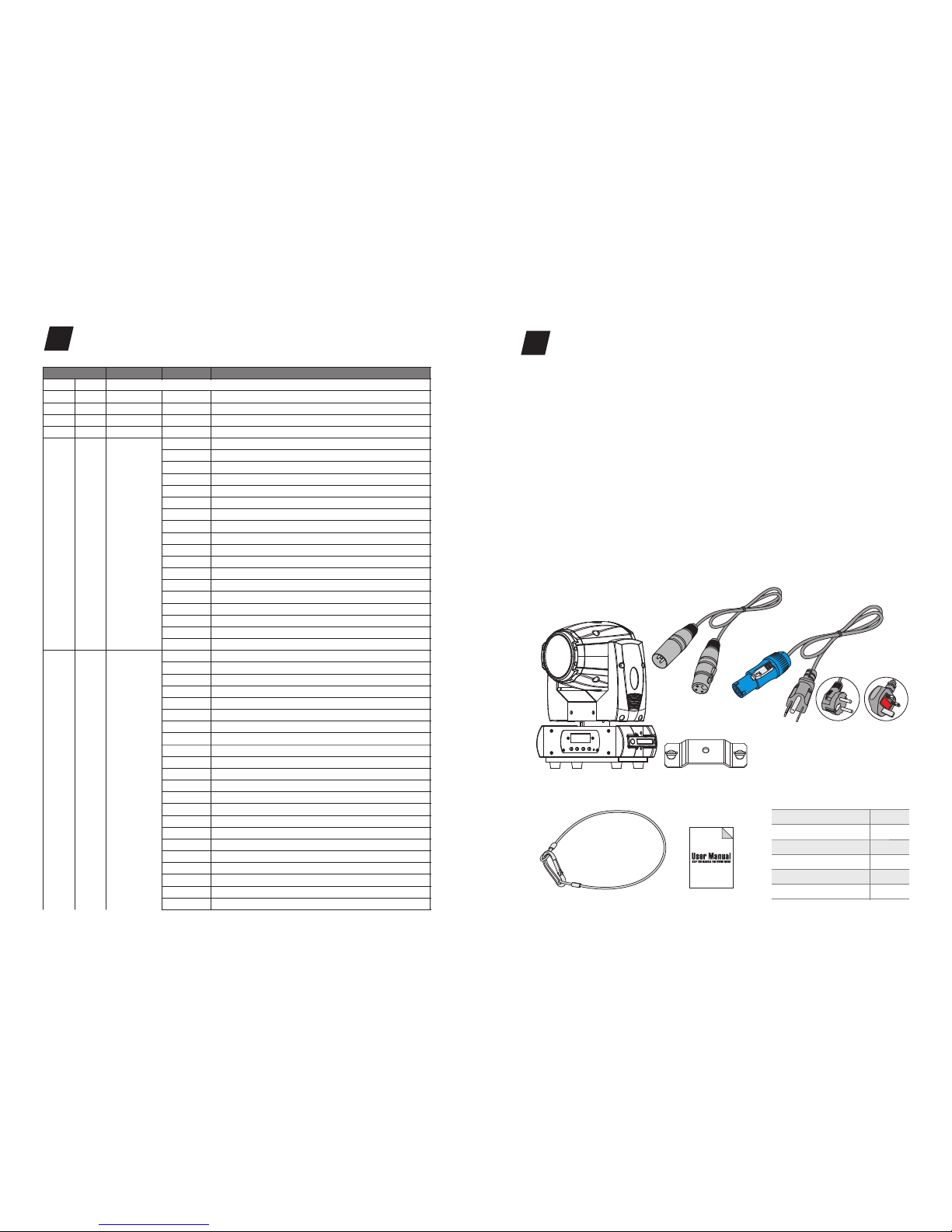
JNR 90L BEAM G
Signal Cable
Power Cable
Hanging Kit
Safety Cable
User Manual
1PC
1PC
1PC
1PC
1PC
1PC
①
②
③
④
⑤
⑥
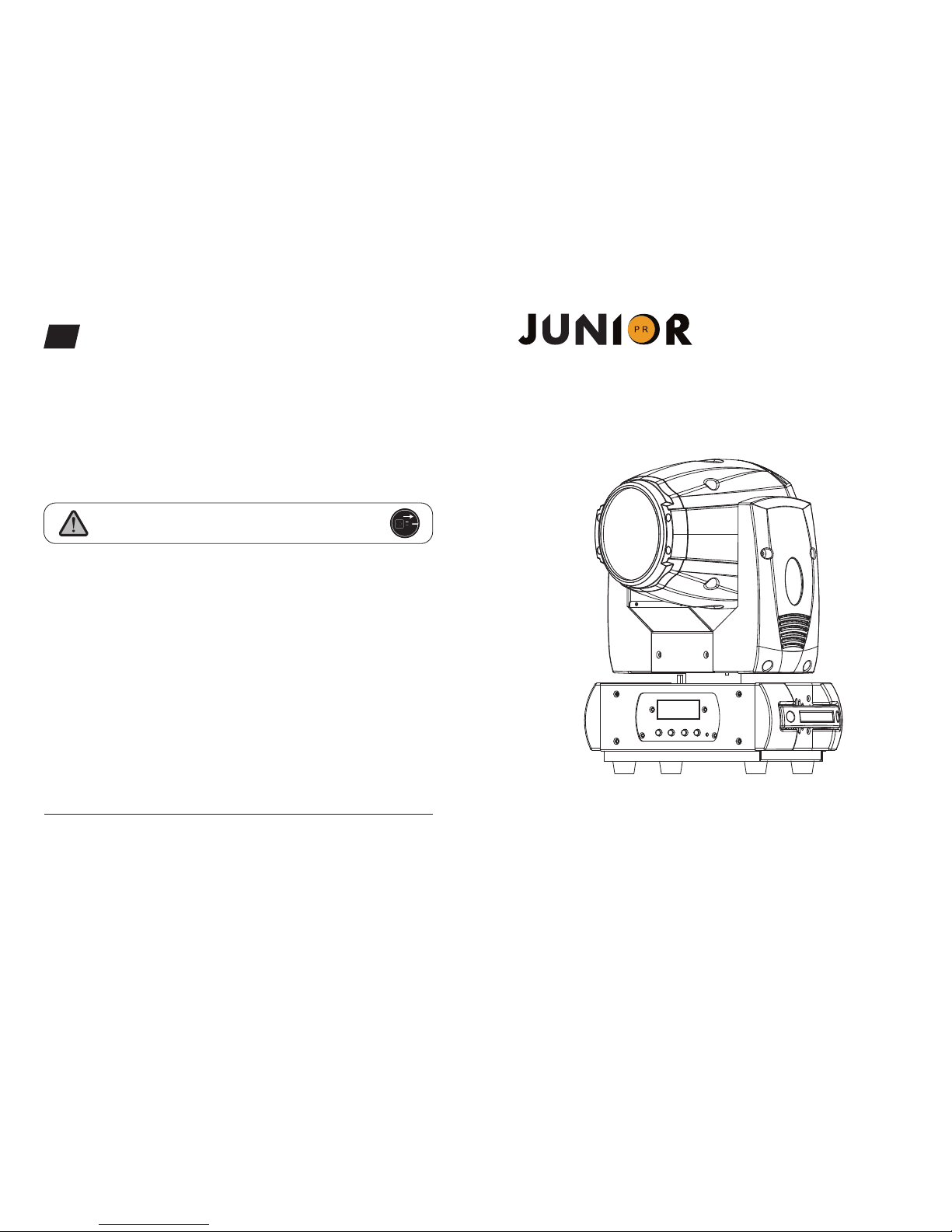
Thank you for choosing our JNR 90L BEAM G. For your own safety, please read this
manual before installing the device. This manual covers the important information on
installation and applications. Please install and operate the fixture with following
instructions. Meanwhile, please keep this manual well for future needs.
The JNR 90L BEAM G is made of a new type of high temperature strength of
engineering plastics and cast aluminum casing with nice outlook. The fixture is
designed and manufactured strictly following CE standards, complying with
international standard DMX512 protocol. It’s available independently controlled and
linkable with each other for operation. And it is applicable for large-scale live
performances, theater, studio, nightclubs and discos.
The JNR 90L BEAM G adopts a 90W 7500K white LED lamp which features high
brightness and stability. Please carefully unpack it when you receive the fixture and
check whether it is damaged during the transportation. And please check whether the
following items are included inside the box:
UNPACKING
2
①
②
④
⑤⑥
③
Euro Standard UK Standard
USA Standard
OPTIONAL
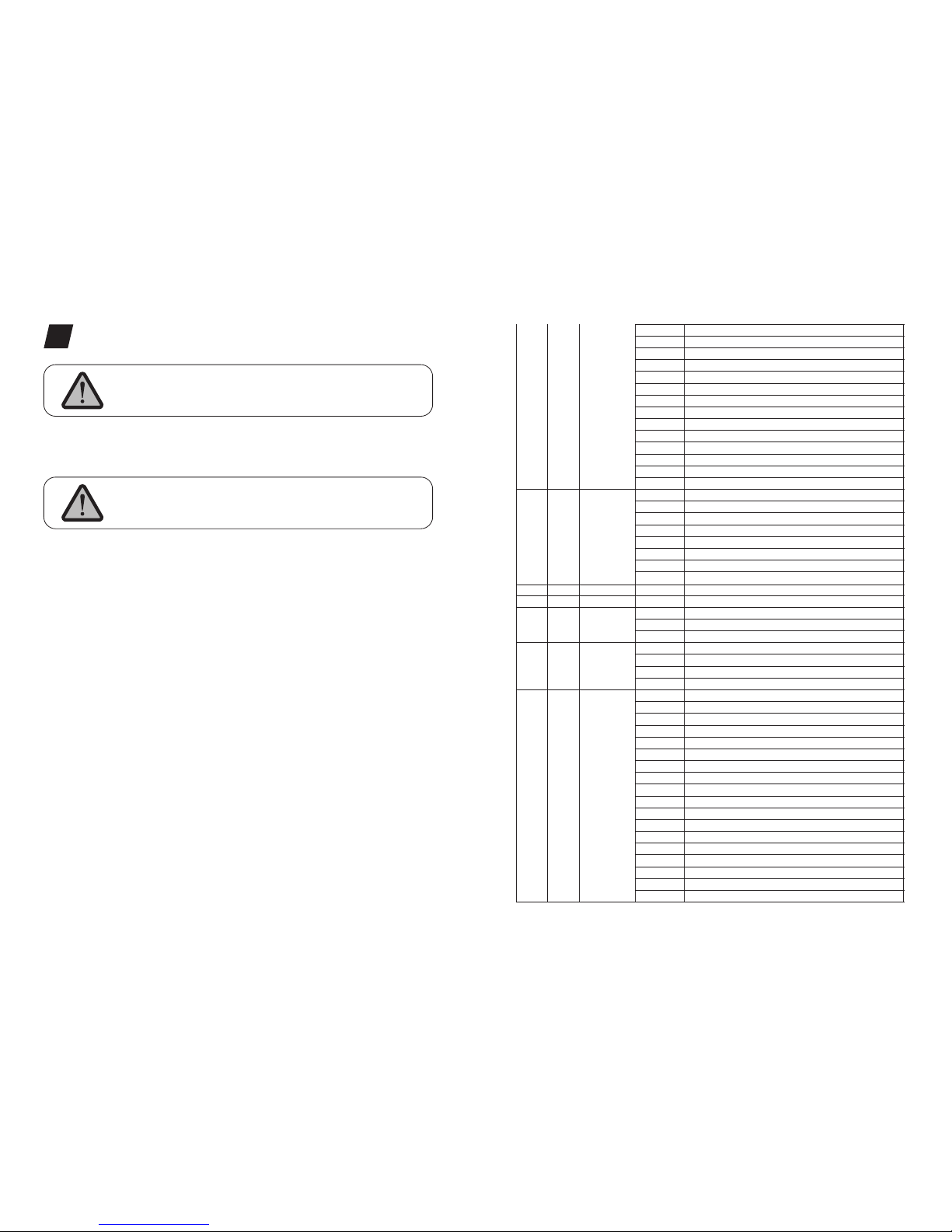
DMX CHANNELS
9
.09.
0-255
0-255
0-255
0-255
0-7
8-15
16-23
24-31
32-39
40-47
48-55
56-63
64-71
72-79
80-87
88-95
96-103
104-111
112-127
128-189
190-193
194-255
0-4
5-9
10-14
15-19
20-24
25-29
30-34
35-39
40-44
45-49
50-54
55-59
60-64
65-69
70-74
75-79
80-84
85-89
90-97
98-105
106-113
114-121
PAN movement
Fine control of movement
movement
Fine control of movement
Open / White
Color 1
Color 2
Color 3
Color 4
Color 5
Color 6
Color 7
Color 8
Color 9
Color 10
Color 11
Color 12
Color 13
Color 14
Forwards rainbow effect from fast to slow
Color rotation stop
Backwards rainbow effect from slow to fast
Open
Gobo 1
Gobo 2
Gobo 3
Gobo 4
Gobo 5
Gobo 6
Gobo 7
Gobo 8
Gobo 9
Gobo 10
Gobo 11
Gobo 12
Gobo 13
Gobo 14
Gobo 15
Gobo 16
Gobo 17
Gobo 1 shake slow to fast
Gobo 2 shake slow to fast
Gobo 3 shake slow to fast
Gobo 4 shake slow to fast
PAN
TILT
TILT
Mode/Channel
Function Values Description
8b
1
2
3
4
16b
1
2
3
4
5
6
PAN
PAN-fine
TILT
TILT-fine
Color wheel
Gobo
wheel
.03.
Features
FEATURES & SPECIFICATIONS
3
Static gobos Colors
•
• 50000 hours life span and low power consumption
• 8/16 bit smooth and precise resolution for PAN/TILT movement
• 360°/540°/630° PAN and 90°/180°/270° TILT movement
• High resolution and high definition glass lens
• 2.5m-15m smooth linear motorized focus
• Scan position memory, auto reposition after unexpected movement
• Specific optic system with 2° projection angle
• Improved optics and flat beam field
• 1 static gobo wheel with 17 gobos plus open
• 1 color wheel with 14 colors plus open
• Variable direction rainbow effect with speed adjustable
• 8-facet prism with variable speed and direction
• 0-100% linear LED dimmer
• 25T/sec high speed LED shutter/strobe effect with variable speed
• Preset variable/random strobe and dimming pulse effect
• 10/12 DMX channels USITT DMX-512
• DMX512, master-slave, and sound activated controllable or auto operation
(7 built-in programs)
• DMX recorder and edit function integrated
• Red background LED display
• Powercon connector IN
• 3-pin XLR connectors IN/OUT
• Fan cooling system
• Constant temperature readout and management function
• 45°C max ambient temperature
• IP20 protection rating
• 55dB at 3’dB rating
• 1*hanging kit
A 90W 7500K white LED lamp
Red Blue Green
Dark
Blue Orange
Yellow
White
Rose
Carmine
UV
CTB Pink
Light
Green
Dark
Yellow
Light
Yellow
Light
Blue
.08.
For installations where the DMX cable has to run a long distance
or is in an electrically noisy environment, such as in a
discotheque, it is recommended to use a DMX terminator. This
helps in preventing corruption of the digital control signal by
electrical noise. The DMX terminator is simply an XLR plug with a
120 Ω resistor connected between pins 2 and 3,which is then
plugged into the output XLR socket of the last fixture in the chain.
Please see illustrations below.
12
3
PIN3
PIN2
120 Ω
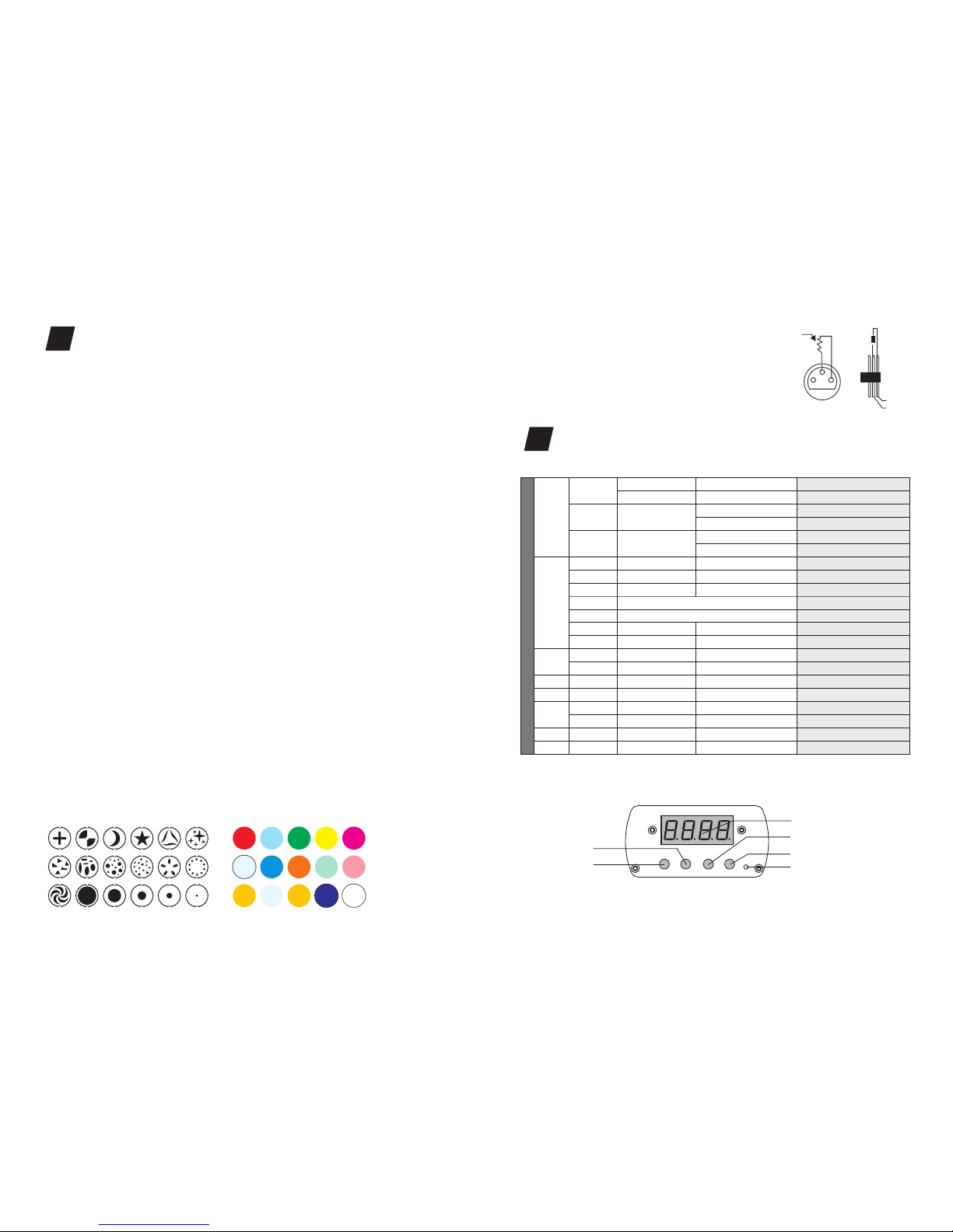
MENU OPERATIONS
8
ADDR
AUTO
SOUN
MIC
LODA
VER
CALI
SPM
Ch14
CH16
ON/OFF
TXXX
PAN
TILT
ON/OFF
ON/OFF
VALU
SLAV
IP1~8
IP1~8
M-XX
ON/OFF
V-1.0~V-9.9
Code(088)
SP1
SP2
630/540/360
270/180/90
CH01—CH12
A001~A499
ALON (AU-A)
(AU-M)MAST
ALON (SO-A)
MAST (SO-M)
MODE
SET
DMX
REST
TEMP
De9r
P-REu
T-REu
ENTER
DMX address setting
Slave
Alone setting
Master setting
Alone setting
Master setting
Mic sensitivity
Data reload
Software version
Calibration code
Calobration channels
SP1
SP2
14CH
16 CH
Reset
Termperature reading
PAN angle options
TILT angle options
PAN inverted
TILT inverted
Func
Up
Down
Enter
LED display
MIC

2°Beam Angle LUX 0.0929=FC×
Photometric Beam Angle Data
.04.
Specifications
Input Voltage:
LED Quantities:
Control Signal:
Control Channel:
Power Consumption:
Dimensions:
Packing Dimensions:
Net Weight:
Gross Weight:
AC90-260V 50/60Hz
1*90W white LED
DMX512, master-slave and sound activated or auto operation
10/12 DMX channels USITT DMX-512
150W
270(D)*149(W)*364(H)mm
345(D)*240(W)*445(H)mm
7.4kg
8.5kg
PHOTOMETRIC DATA
4
Beam
Diameter
ø 17.5 ø 33.5 ø 50 ø 67 ø 109
0m
6829 /
73510
2°
2.5 m 5m 7.5 m 20m10m 15m
1828 /
19680
744 /
8010
461 /
4960
114 /
1230
99 /
1070
ø 144
( FC/
LUX )
cm
.07.
Regardless of the rigging option you choose for your , always be sure
to secure your fixture with a safety cable. The fixture provides a built-in rigging point
for a safety cable on the hanging bracket as illustrated above. Be sure to only use the
designated rigging point for the safety cable and never secure a safety cable to a
carrying handle.
JNR 90L BEAM G
DMX-512 CONTROL CONNECTIONS
7
Connect the provided XLR cable to the female 3-pin XLR output of your controller and
the other side to the male 3-pin XLR input of the moving head. You can chain multiple
Moving head together through serial linking. The cable needed should be two core,
screened cable with XLR input and output connectors. Please refer to the diagram below.
DMX-512 connection with DMX terminator
DMX Output
3-Pin XLR Socket
DMX Input
3-Pin XLR Socket
1:Ground
2:Data(-)
3:Data(+)
1 2
3
12
3
1
2
3
1
2
3
COMMON
DMX+
DMX-
DMX512 IN
3-PIN XLR
DMX512 OUT
3-PIN XLR
DMX IN
DMX OUT
POWER IN
FUSE
POWER SWITCH
POWER IN
DMX IN
364
193
97
179
184
152
270 149
Table of contents


