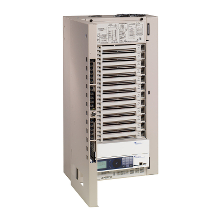
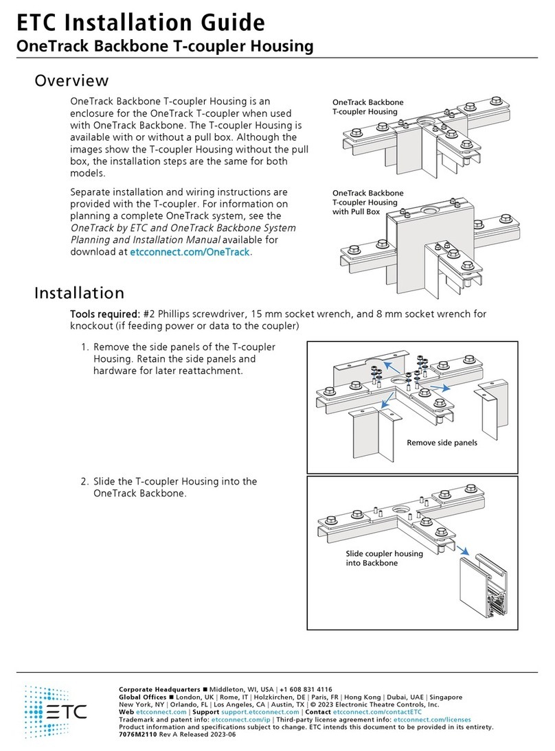
ETC Sensor+ SR+ Series User manual

Part Number: 7141M2300 Rev: C
Released: 2021-03
Sensor+
Enclosure (SR+/HSR+ Series)
CEM
+
to CEM3 Retrofit Manual

Introduction 1
Introduction
This manual is intended to guide ETC Service Technicians
through the process of upgrading existing Sensor+
enclosure installations to Sensor3 enclosures with a CEM3
control module. This manual covers SR+ or HSR+ 6, 12, 24
and 48 permanent installation enclosures.
If you purchased this retrofit kit as part of a power
package, see support.etcconnect.com/Source_Articles/
ETC/Power_Controls/General/ETC_Upgrades_Program or
scan the QR code to the right for more information.
Overview of this Manual
•
Preparation (page 5)
: Before you open the enclosure
•
Remove the Old CEM (page 6)
: Label and remove the existing equipment
•
Attach New Power Harness (page 7)
: Adapt and connect the power harness for the new
backplane
•
Install the New Backplane (page 9)
: Transfer the wiring and install new components
•
Change out the AF Cards (if present) (page 11)
: Remove the existing Advanced Feature cards and
install the new ones
•
Change out the Beacon PCB (page 11)
: Replace the existing beacon primary circuit board (PCB)
with the new one
•
Enclosure Door (page 12)
: Replace the beacon acrylic in the door and replace the enclosure label
•
Verify the Retrofit (page 12)
: Put the dimmers back in the enclosure and power up the enclosure
•
Configure the CEM3 (page 13)
: Program a configuration for the CEM3
•
Final Steps (page 13)
: Clean up waste and archive CEM3 configuration

2CEM3 Sensor+ Rack Retrofit Manual
Document Conventions
This document uses the following conventions to draw your attention to important
information.
All ETC documents are available for free download from our website: etcconnect.com.
Safety
Please note the following safety warnings before use:
• Disconnect power from the enclosures before all maintenance.
Note:
Notes are helpful hints and information that is supplemental to the main
text.
CAUTION:
A Caution statement indicates situations where there may be
undefined or unwanted consequences of an action, potential for
data loss or an equipment problem.
WARNING: A Warning statement indicates situations where damage may occur,
people may be harmed, or there are serious or dangerous
consequences of an action.
WARNING: RISK OF ELECTRIC SHOCK! This warning statement indicates
situations where there is a risk of electric shock.
WARNING:
RISK OF DEATH BY ELECTRIC SHOCK! Failure to disconnect all power
to the dimmer rack before working inside could result in serious
injury or death.
AVERTISSEMENT :
RISQUE DE MORT PAR ÉLECTROCUTION! Travailler à l’intérieur du
rack de gradation sans avoir déconnecté le courant peut entrainer
des blessures graves, voire mortelles.
De-energize main feed to the dimmer rack and follow appropriate
Lockout/Tagout procedures as mandated by NFPA 70E. It is
important to note that electrical equipment such as dimmer racks
can present an arc flash hazard if improperly serviced. This is due to
the high amounts of short-circuit current available on the electrical
supply to this equipment. Any work must comply with OSHA Safe
Working Practices.

Introduction 3
Help from ETC Technical Services
If you are having difficulties, and your problem is not addressed by this document, try the ETC
support website at support.etcconnect.com or the main ETC website at etcconnect.com. If
none of these resources are sufficient, contact ETC Technical Services directly at one of the
offices identified below. Emergency service is available from all ETC offices outside of normal
business hours.
When calling for help, take these steps first:
• Prepare a detailed description of the problem
• Go near the equipment for troubleshooting
• Find your notification number if you have called in previously
ETC, Inc.
Americas
Technical Services Department
3031 Pleasant View Road
Middleton, WI 53562
800-775-4382 (USA, toll-free)
+1-608 831-4116
ETC GmbH
Germany, Austria, Switzerland, Eastern
Europe, and Russia
Technical Services Department
Ohmstrasse 3
83607 Holzkirchen, Germany
+49 (80 24) 47 00-0
techserv-germany@etcconnect.com
ETC Austin
High End Systems Products
Technical Services Department
2105 Gracy Farms Lane
Austin, TX 78758 USA
800-890-8989 (USA, toll-free)
+1-512 836-2242
ETC France
France
Zone Urbaparc -
Bâtiment E
6 Boulevard de la Libération
Saint-Denis, 93200
+33 1 4243 3535
ETC Ltd
Europe, Middle East, and Africa
Technical Services Department
26-28 Victoria Industrial Estate
Victoria Road,
London W3 6UU England
+44 (0)20 8896 1000
ETC Asia
Asia
Technical Services Department
Room 1801, 18/F
Tower 1, Phase 1 Enterprise Square
9 Sheung Yuet Road
Kowloon Bay, Kowloon, Hong Kong
+852 2799 1220

4CEM3 Sensor+ Rack Retrofit Manual
Unpack and Organize
The table below lists the parts and components needed to retrofit a Sensor+ rack (SR+ or HSR+ 6, 12,
24, or 48) to become a Sensor3 rack with a CEM3.
Bag Parts/Components
ETC Part Number
SR+Enclosure
7141K1101
HSR+ Enclosure
7141K1004
1
CEM+ to CEM3 Backplane Power Adapter
Harness
7141B7007
11
Cable tie 4" Hi-temp Black
HW7121 88
Tie-mount (sticky-back)
HW741 44
Sensor3 Beacon Door Acrylic
7141A4050 11
2
Screw 6-32 X 3/8 Ph PH MS CP W/Patch
HW222 3 3
Screw 8-32 X 3/8 Ph PH MS CP W/Patch
HW377 3 3
CEM3 Backplane 1/8” #8 screw spacer
HW9343 3 3
3CEM3 Beacon Assembly
7140B5620 11
-
Sensor3 ESR/HSR Install Enclosure Backplane
Assembly
7144A2100-CFG
- 1
-Sensor3 SR Install Enclosure Backplane Assembly
7141A2103-CFG 1 -
-Sensor3 Installation Rack Door Label
7141A4049 1 1
Additional Items
Sensor3 AF Card (Optional)
7150B5623 up to 4*
CEM3
7140A1000 1
Required Tools
#1 Phillips screwdriver
#2 Phillips screwdriver
1/4” flat head screwdriver
Diagonal wire cutter
Permanent marker
Wire strippers

The Retrofit 5
The Retrofit
Preparation
1: Use the Sensor+ Connect web interface to download and save the current configuration out of
the CEM+ for later reference. Instructions on saving your configuration from this interface can
be found in any CEM+ Software Release Note or any CEM+ Configuration Manual available for
download at etcconnect.com.
2: Turn off main power to the enclosures.
3: Remove the eight dimmer modules above the CEM+ (if retrofitting an SR+48 rack, remove the
eight modules below the CEM+ as well). Note and document the modules’ order/positioning in
the enclosure for proper insertion and configuration later.
4: Use a digital voltmeter and VERIFY that power is off by checking voltages for all combinations
between the phase bars, neutral and ground.
5: Remove the CEM+ from the rack.
WARNING:
RISK OF DEATH BY ELECTRIC SHOCK! Power down the rack before
removing the CEM3. Only remove modules with the rack powered off,
following these instructions or as instructed by ETC Technical Services.
AVERTISSEMENT :
RISQUE DE MORT PAR ÉLECTROCUTION! Mettez le rack de gradation
hors tension avant de retirer le CEM3. Ne retirez les modules de
gradation ou de contrôle que lorsque le rack est éteint, en suivant ces
instructions ou selon les instructions des services techniques ETC.
Removing modules exposes the phase bars inside of the rack. When the
rack is powered on, phase voltages inside the rack can cause injury or
death. When the rack is powered on, modules should only be removed
by qualified installers or electricians.
WARNING:
RISK OF DEATH BY ELECTRIC SHOCK! Failure to disconnect all power to
the dimmer rack before working inside could result in serious injury or
death.
AVERTISSEMENT :
RISQUE DE MORT PAR ÉLECTROCUTION! Travailler à l’intérieur du rack
de gradation sans avoir déconnecté le courant peut entrainer des
blessures graves, voire mortelles.
De-energize main feed to the dimmer rack and follow appropriate
Lockout/Tagout procedures as mandated by NFPA 70E. It is important to
note that electrical equipment such as dimmer racks can present an arc
flash hazard if improperly serviced. This is due to the high amounts of
short-circuit current available on the electrical supply to this equipment.
Any work must comply with OSHA Safe Working Practices.
6CEM3 Sensor+ Rack Retrofit Manual
Remove the Old CEM
1: Disconnect the multi-colored DMX ribbon cable and Cat5 cable from the backplane.
2: Disconnect the power cable from the rear of the CEM+ backplane.
3: Disconnect the dimmer output ribbon cables from the backplane. As you remove the ribbon
cables, mark them with a permanent marker to indicate the proper order for reattachment
(Dimmers 1–24, 25–48, and so on). There may be stickers on the ribbon cables already, however
these may refer to cable length and not dimmer outputs. They should not be used as a reference
to these instructions.
4: Unscrew the backplane metal from the enclosure. (One screw in each side upper-corner - two
screws total.) Discard these screws. Replacement screws with thread locker are provided
(ETC Part# HW377) and will be used later.
5: Push the backplane towards the back of the enclosure to free the backplane side tabs.
6: Bend the sides in towards the center (out of the sides of the enclosure).
7: Pull one side forward to angle the backplane then remove the backplane metalwork from the
enclosure. Discard the old backplane.
6
88
9
7
Remove the
backplane screws

The Retrofit 7
Attach New Power Harness
1: Connect the old power connector to the new power harness adapter found in the kit. The
connectors are keyed - the power connectors only fit one way.
2: Run the green ground wire from the power harness adapter between the bus bar and the
enclosure wall avoiding any interference with other wires in the enclosure.
3: Carefully route the ground wire to any open terminal in a grounding strip inside the enclosure.
Grounding terminal screws can be loosened or tightened with a flat-blade or square drive
screwdriver.
4: Use a wire tie to secure the ground wire to the wires that travel from the mated power harness
connectors.
New Power Harness
Run Ground behind bus bar Secure Ground in rack
ground terminal

8CEM3 Sensor+ Rack Retrofit Manual
Backplane Settings
Upgrade kit backplanes ship from the factory with all DIP switches in the off (down) position. You will
have to set the DIP switches on the new backplane to match your rack. You will also have to verify the
termination switch settings.
1: Set the DMX termination switches for each port to "Off" unless the port is the last position in
the DMX chain.
• If there are both DMX In and Thru connections to the port, the enclosure is not last in the
chain. DMX Thru connections can be made either using two pairs of wires in one terminal
block, or using the DMX Thru connector.
• If there is only one set of DMX wires in the connector and the DMX Thru is not used, the
enclosure is the last in the chain.
• If there is no DMX wire connected, leave the termination switches off.
2: Using a precision screwdriver, set the DIP switches to match your enclosure type according to:
• number of modules (6, 12, 24, or 48)
• whether the enclosure has Advanced Features (AF)
Use the following chart to determine your required DIP switch settings:
“On” position = switch pushed to the top
DIP switch Number
EnclosureModel 12345678
SR3-6 On On
SR3-6AF On On On
SR3-12 On
SR3-12 AF On On
SR3-24 On
SR3-24 AF On On
SR3-48
SR3-48 AF On
Set termination to “Off”
(middle position) Set DIP switches

The Retrofit 9
Install the New Backplane
1: Remove the three-pin Phoenix connector that ships attached to the rear of the backplane. It will
not be used in this retrofit.
2: Verify that the four-pin Molex caps are in place over the connectors next to where the phoenix
connector was attached.
3: Bend one arm of the backplane metal in towards the opposite arm (about 15º).
4: Insert the backplane metal on an angle. Then straighten it once it is past the face of the
enclosure. Push it into the enclosure far enough that it stays in place, but leave yourself some
room to make the power and data connections.
Connect power and data to the backplane
5: Install the dimmer output ribbon cables. Open the black retaining tabs for each connector until
they are at a 45° angle to the backplane. Press the connectors into their respective locations until
the tabs lock in place at a 90° angle to the backplane. Make sure the proper side is facing up on
each connector and that each connector is fully seated.
6: Install the power harness. Look at the pin shapes for proper orientation. It will only fit one way.
7: Install the DMX connections. DMX may use screw-terminal or IDC connectors. The wires travel
out of the top of the CEM3.
• DMXA-1 is common
•DMXA-2isDMX-
•DMXA-3isDMX+
• DMXB-1 is DMXB common
•DMXB-2isDMX-
•DMXB-3isDMX+
Verify Remove

10 CEM3 Sensor+ Rack Retrofit Manual
8: Install the 3-pin beacon connector. The wires travel out of the bottom of the
CEM3.
9: Connect the Cat 5 Ethernet cable to the RJ-45 connector on the CEM3 backplane.
(Not shown in the drawing below for clarity.).
Finish Installing the Backplane
10: Push the backplane completely into place in the rack. Be careful not to disrupt the power and
data connections you just made. Make sure none of the wiring becomes stressed or pinched.
11: Insert the backplane tabs in the side of the enclosure.
12: With the tabs fully inserted in the sides of the
enclosure, pull the backplane towards the
front of the rack to line up the screw holes in
the upper side corners to line up.
13: Install one screw with a sleeve in each side
upper-corner of the backplane.
Transfer Panic Wiring (if present)
If the enclosure had a panic connection in the previous backplane configuration, terminate the panic
connections to the new backplane.
1: Locate the wire pair for the panic connection.
2: Cut and strip 3/16” (5 mm) of insulation from the wires.
3: Connect the panic wires to the “PANIC SEND” and “PANIC RETURN” terminals.
4: Move the panic configuration switch (to the right of the terminals) to the appropriate position:
• NO for Normally Open contact types
• NC for Normally Closed contact types
Note:
You cannot use the old screws without the additional shoulder-sleeve as they will
block the CEM3 from being fully inserted.
123
J16
Beacon
Pin-out
Black
Blue
Red
DMX ADMX B
DMX Thru
Beacon
Power
CEM3 Ribbon Cable Layout
1
2
3
4
(25-48) (73-96)
(49-72)
(1-24)
Screw with
sleeve

The Retrofit 11
Change out the AF Cards (if present)
If your enclosure supports Advanced Features (AF) you will need to replace the AF cards as well.
AF cards are located on the right side of the dimmer module slot between the copper neutral busses
and the dimming circuitry cards.
To replace the AF cards:
1: Remove the old AF cards by flipping the white tab
on the cards into the down position.
2: Pull the old cards out of the slots.
3: Set the DIP switches on the new cards according to
the table below. Only the first two DIP switches are
used.
4: Flip the white tab up to prevent it from interfering
with the dimmer module.
5: Slide the new AF cards completely into the vacant
slots starting with card #1 in the top. The number of
cards depends on rack size (see the table below).
Change out the Beacon PCB
1: Remove the two screws that hold the beacon PCB in the face of the enclosure.
2: Pull the PCB down from inside the enclosure case. (The
wire harness will only allow a few inches of movement).
3: Note the orientation of the connector and unplug the
wire harness from the old beacon PCB.
4: Attach the wire harness to the new beacon PCB,
making sure the connector is in the same orientation as
before.
5: Install the new beacon PCB (ETC part # 7140B5620)
with two screws (ETC part # HW222). (Three new
screws of the same type are provided in case the old
ones were damaged during the removal process.)
Note:
Only the first two DIP switches are used.
Note:
Be sure to use a properly sized screwdriver (#2 Phillips) and a good amount of force,
because these screws are kept in place with thread locker. Don’t worry about
damaging the existing screws (replacements are provided) or shearing off the heads
of the screws (the screw shanks are threaded into the PCB’s standoffs).
2
1
Card 1
Card 2
Card 3
Card 4
S
W
1
S
W
2
S
W
3
S
W
4
S
W
5
S
W
6
S
W
7
S
W
8
1
2
3
4
SR3-6
(E)SR3-12
(E)SR3-24
(E)SR3-48
ESR3-36
0
1
0
1
0
1
0
1
0
0
0
0
0
0
0
0
0
0
0
0
0
0
0
0
0
0
0
0
0
0
0
AF Card Addressing (1=ON, 0=OFF)
New blue-LED
beacon PCB

12 CEM3 Sensor+ Rack Retrofit Manual
Enclosure Door
1: Remove the old Sensor beacon acrylic in the door and discard by loosening the two retaining
screws with a #2 Phillips screwdriver.
2: Install the Sensor3 beacon acrylic in the door with the
longer edge toward the center of the door.
3: Carefully peel the old Sensor label from the front of
the door and discard.
4: Clean the door surface to remove any dirt or old
adhesive. Ensure that the door is completely dry
before continuing to step 5.
5: Apply the new Sensor3 label to the front of the door. Line up
the label to the top of the enclosure door and be sure the
label is straight. Press and wipe with the removed paper
backing to make sure the label is flat and smooth and
properly adhered to the enclosure door.
6: Repeat the above steps for all retrofitted enclosures.
Verify the Retrofit
1: Put the dimmer modules back in the rack in the correct/original order, making sure all dimmer
circuit breakers in the enclosure are turned "Off."
2: Put the CEM3 in the enclosure in Test Mode (enabled using the switch located on the right-hand
side of the PCB).
3: Power up the enclosure.
4: Check that the CEM3 powers up and the enclosure fan turns on.
5: Check that the signal lights on all dimmers are illuminated. If not, power down the enclosure and
verify that the CEM3 and all ribbon cables are fully and correctly seated.
Note:
The only rack errors should be a lack of DMX on the ports if the DMX source is not
present.

The Retrofit 13
Configure the CEM3
1: Change the CEM3 from Test Mode to Normal Mode (enabled using the switch located on the
right-hand side of the PCB).
2: Configure the enclosure to reflect the dimmer module types installed. Verify that the enclosure
type is correct (CEM3 should have determined this from the DIP switch settings - see
Backplane
Settings
on
page 8
). Use the front face panel interface to configure the CEM3. See the
CEM3
Quick Guide
that ships with the CEM3 for more information.
3: Configure the data types that will be used (DMX and sACN) including the enclosure patch.
4: After the dimmer ribbon cables are connected in the correct order, set one dimmer from each
group of twelve slots on at a time, and then verify the correct dimmer signal light as it illuminates.
5: Verify that all sources of control (DMX, sACN, Preset stations) function correctly.
6: Turn all dimmer circuit breakers back on.
Final Steps
1: Collect and properly dispose of all debris created during the upgrade process.
2: For future service needs, it is recommended that you send copies of the final CEM3 configuration
job number and the date the configuration was adjusted.
Note:
If AF cards are present, it may take some time for them to fully load their software.
Note:
PCBs (such as the backplane termination board, beacon board, and AF cards) may be
deemed hazardous e-waste by some municipalities. Please dispose of in accordance
with local requirements.
Note:
Send CEM3 configuration files saved out of the Sensor3 enclosure, not configuration
exported from ETC Concert (if used).

Corporate Headquarters
Middleton, WI, USA | +1 608 831 4116
Global Offices
London, UK | Rome, IT | Holzkirchen, DE | Paris, FR | Hong Kong | Dubai, UAE | Singapore
New York, NY | Orlando, FL | Los Angeles, CA | Austin, TX
Web etcconnect.com | Support support.etcconnect.com | Contact etcconnect.com/contactETC
© 2021 Electronic Theatre Controls, Inc. | Trademark and patent info: etcconnect.com/ip
Product information and specifications subject to change. ETC intends this document to be provided in its entirety.
7141M2300 Rev C Released 2021-03
This manual suits for next models
9
Table of contents
Other ETC Enclosure manuals

ETC
ETC OneTrack Backbone End Feed Housing User manual

ETC
ETC OneTrack Backbone T-coupler Housing User manual

ETC
ETC Unison AX Series User manual

ETC
ETC 7180A1018 User manual

ETC
ETC Unison ERn2-W User manual

ETC
ETC OneTrack Backbone I-coupler Housing User manual

ETC
ETC 7180A1018 User manual

ETC
ETC DRd6-12-120 User manual