ETC LIGHTHACK BOX 1 User manual

1
#lighthack box 1 Revision: 08
Assembly Instructions
Parts List
ETC PN
VendorPN
Qty
Description
4201B9001
Mouser 782-A000066
1
Arduino Uno R3
DS221-F
Sparkfun LCD-00255
1
HD44780 Display Module
S846-F
Cherry MX1A-L1NB
3
Cherry MX Red Key Switch
4152A4039
3
Black Eos®-Style Key Cap
L1243-F
Digikey PEC11R-
4220F-S0012-ND
2
Rotary Encoder with Panel Mounting Hardware
4201A4003
Adafruit2055
2
Encoder Knob
4240B7011
1
10 kΩ Potentiometer
4201B7001
1
Red Wire Solid Core 22AWG/0.65mm22-3'/60-90cm
4201B7002
1
Black Wire Solid Core 22AWG/0.65mm22-3'/60-90cm
4201B7003
1
White Wire Solid Core 22AWG/0.65mm22-3'/60-90cm
4201B7004
1
Yellow Wire Solid Core 22AWG/0.65mm22-3'/60-90cm
4201B7005
1
Blue Wire Solid Core 22AWG/0.65mm22-3'/60-90cm
J4630
3
5-position Wago Wire Connector
J4629
1
3-position Wago Wire Connector
W6378
1
USB Cable,A to B
HW0006
10
Machine screws #2-56x3/16"(~5mm)
HW9489
5
Standoffs#2-56x1/4"(~6mm)
4201A4001
Hammond 1591U
1
Enclosure with lid and screws
Tools
Necessary:
- Wire strippers and cutters
- Soldering iron and solder
- Philipsscrewdriver
- Drill with 1/8" / 3mm, 1/4" / 6mm, 1/2" / 12mm bits
- Rasp/File or Chisel
Helpful:
- Needle-nose pliers
- X-Acto knife or other sharp knife
- Electricaltape
- Thickdouble-sidedtape
Software
- Arduino Integrated Development Environment (IDE). Download from
https://www.arduino.cc/en/Main/Software
- Arduino sketch (code) for box 1. Download fromhttps://github.com/ETCLabs/lighthack
- Arduino OSC library.Download fromhttps://github.com/CNMAT/OSC
- Arduino to Eos TestApplication. Download fromhttps://github.com/ETCLabs/lighthack

3
Test the Software
It is recommended that you test the Arduino before starting the assemblyof the enclosure.
1. Download the source code fromhttps://github.com/ETCLabs/lighthack, andextract the .zip
file (or clone the repository if you're git-savvy!).
2. Open the Arduino USB Test sketch (lighthack-
master\test_tools\usb_test\usb_test_sketch\usb_test_sketch.ino) in the ArduinoIDE.
3. Before the sketch will compile, we need to add additionalcode (calleda "library")
sothat the Arduino knows howto speakOSC. Download the library as a .zip
from https://github.com/CNMAT/OSC.
4. In the Arduino IDE, select Sketch > Include Library>Add .ZIPLibrary... and
select the OSCzip file youdownloaded
5. Press the check mark to verify your sketch.

4
6. Connect the Arduino to your computerusing the USBcable.
7. The Arduino IDEwill automatically detect your Arduino Uno and select it. You can verify
this in the Toolsmenu:
8. Press the arrowto upload your sketch to the Arduino.

5
9. After the sketch has been loaded, the Arduino’slights should have the L and ONlights solid
and the TXlight blinking once per second:
10.Launch Eos software, open Tab 99 Diagnostics, and lookfor messages that
read: “OSC USB Device Handshake Complete [OK]”
“OSC USB Device Handshake Initiated [ETCOSC?]”
The TXand RX lights should blink in sequence once persecond.
Press “Incoming OSC” and you should see repeating messages of
“[OSC Packet] /eos/ping,” and a number countingup
These messagesindicate that yourArduinoand Eos are talking to each other.
The RXLED on your Arduino should also start blinking.
11.Exit the Eos software.
12.Now, load the main box_1_src.ino code. If you've added the OSC library
properly,the verification will besuccessful.
13.Press the arrowto upload your sketch to the Arduino.

6
14.After the sketch hasbeen loaded, startEosagain and look for the same Handshake
messages. Note that in this mode, the Arduino doesnot send the repeatingPing
messages, and the Arduino’s TX/RXLEDs will onlyblink once.
If text does notappear, followthe troubleshootingstepsat the end of this document.
Prepare the Enclosure
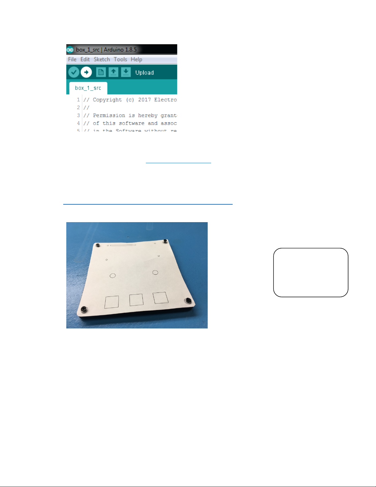
15.Print outthe paper template, making sure to disable any"fit to paper"or scaling options so
that it prints at actualsize. The template isfound at
https://github.com/ETCLabs/lighthack/tree/master/box_1.
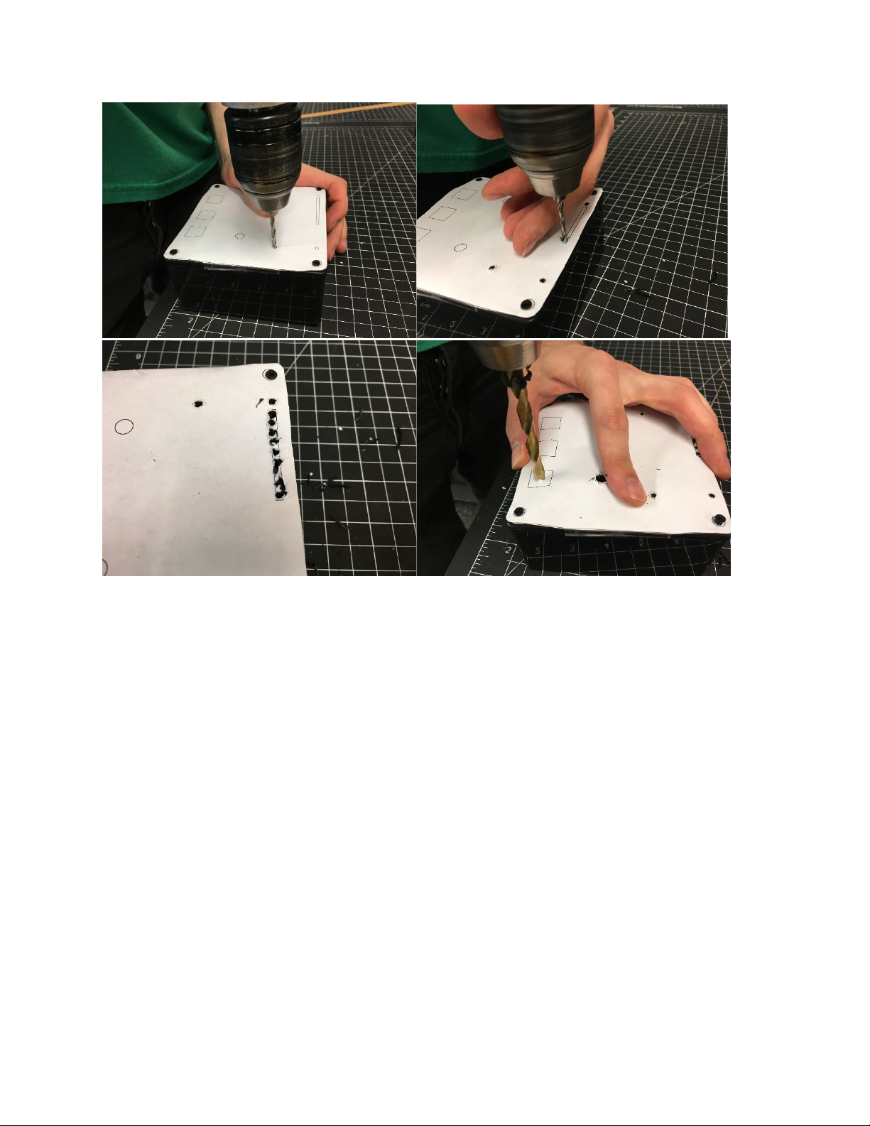
16.Cut out the template and layitover the top of the enclosure lid, using the screwholesor
tape to make sure it doesn't move.
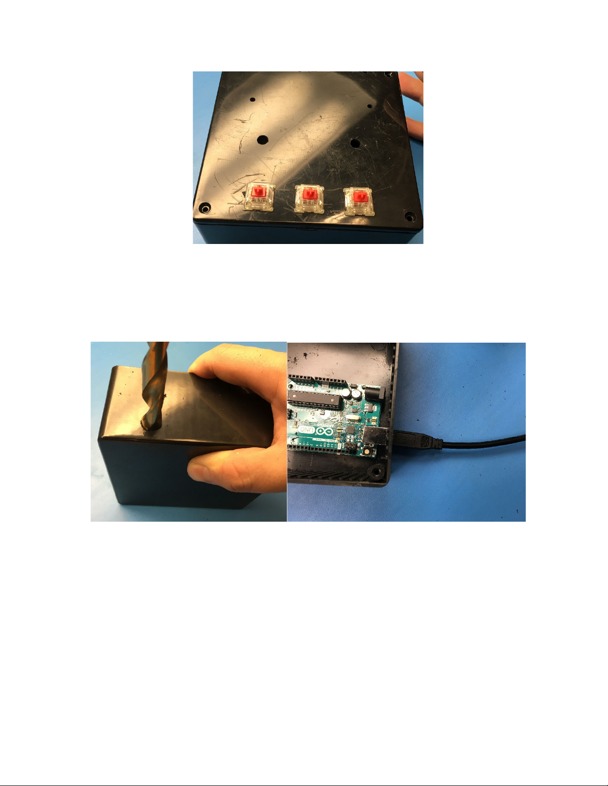
17.Drill outthe holes using the proper size drill bits. Drill starter holes in the square cutouts.
For the long rectangular slot, you may want to drill a few holes right next to each other as a
starting pointfor a file.
18.Using thistemplate, the LCDdisplaywill be mounted to the outside of the lid. Skip to Step
13 if you want to followthe template. If you would like to mount the display to the inside of
the box, cuta rectangular hole in the enclosure lid slightly largerthan the face of the LCD
screen.
TIP: Don't feel like
drilling and filing? Use
the provided 3D
Printer template to
print a "pre-drilled" lid.

7
19.Using a square or rectangularfile, file out the squareholesand slot (or use yourpreferred
method of making square holes).
20.Test fit the Cherry MX Red switchesinto the square holes asyou file to make sure you
have the right size.

8
21.Fromthe underside of the lid, use a file to bevel the edgesof the square holes.This makes
the plastic surroundingthe hole thinner so that the Cherry MXRed switches can clip in
properly.
TIP:
It may be helpful to
trace the edges of the
square holes into the
plastic with an X-Acto
knife, and then remove
the paper.

9
22.Line up the Arduino with a side of the box in order to estimate the location of the hole.
We've found a good location to be 1"/25mmin froma corner and ½"/12mm up fromthe
bottom. Use a ½"/12mm drill bit to drill a hole for the USB connector. Make sure you can
connect a USB cable to your Arduino through the hole.
23.Drill a hole for the USB connector. If desired, add a second1/2" hole to mount the
potentiometer.

10
Connect t he Electronics
24.Cut appropriate lengths of wire to connect the three buttons andtwo rotary encoders to the
Arduino as shown in the wiring diagram. The wire colors in the wiring diagramare a
suggestion.The wire colors in your kitmay vary.
25.Strip approximately½"/12mmof insulation fromeither side of each length of wire.
26.Solder one end of each wire length to pinson the rotary encoders and key switches.
27.Use the Wago connectors where multiple black (ground)wires need to be connected
together.Onlythree of the five leads on the encoders need to be connected, as shown.
You will want to have the key switches inserted into the enclosure lid alreadywhen you do
this.

11
28.Cut appropriate lengths of wire to connect the display and contrast adjustment
potentiometer to the Arduino asshown in the wiring diagram.
29.Cut offthe connector fromthe potentiometer.
30.If you are mounting it to the box, thread on the rubber washer and lockingring, stringthe
wire through the box, then tighten with the nut. This hasto be done beforesoldering.
31.Strip approximately½"/12mmof insulation fromeither side of each length of wire.
32.Solder one end of each wire length to the display asshown.
33.Connectthe middle pin of the potentiometer to the displayas shown.
34.Connectthe free end of each wire to the appropriate pin on the Arduinoas shown in the
wiring diagram.

12
35.Before mounting everythingin the enclosure and finishing the assembly, the electronics
should be tested.Connectthe Arduino to a Win7 Eos Family console or a computer
running ETCnomad.
36.Test the device by patching a moving light,selecting it and using the encodersto modify
the pan and tilt values. Check to make sure that the "next" and "last" buttons cycle through
the channels and the "fine"buttonswitches between coarse and fine adjustment.
Finish the assembly
Now that your module has been tested, it's time to put it in the enclosure.
37.Insert the two encoders throughthe holesfromthe inside ofthe lid.
38.Use the included panelmounting nuts and washers to securethe encoders.
39.Disconnect the screen fromthe Arduino andfeed its wires through the rectangularslot. If
mounting to the inside ofthe box, you would instead mount the LCD screen inside the lid
using the standoffs on the underside of the lid.
40.Secure the screen in place using eight #2-56 machine screws (four fromthe top, and four
fromthe bottom) and either the ¼" (~6mm) or ½" (~12mm) standoffs. Extra screws and
standoffs are provided.

14
44.Secure the face plate to the enclosure usingthe four black screws.
TIP:
You may want to use
some electricaltape for
cable management.

15
45.Press-fit the keycapsand encoder fingerwheels onto the key switches and encoders.
46.Re-test the module to make sure everything stillworks.Congratulations! You're done.

16
Troubleshooting
Problem
Possible solution
Arduino software displays an orangeerror
message when I try to verify using the check
mark icon
Verifythat the OSC library is installed using
the procedure discussed in the Test the
Software section.
Device mostly works but a button or an
encoder is notworking
Checkthe solder connectionsfor cold or
broken joints.
Checkthe connections to the Arduino.
Make sure the button or encoder is
connected to the properArduinopinsas
shown in the wiring diagram.
One or both encodersare reversed
Look near the top ofthe source code
(box_1_src.ino) for linesthatsay"#define
PAN_DIR FORWARD" and "#define
TILT_DIR FORWARD".To reverse the
direction of an encoder, setthe
corresponding line to REVERSE, i.e. "#define
PAN_DIR REVERSE".
Screen "glitches" or displays strange
characters
Checkthe screen's solder connections for
cold joints.
Checkthe screen's connections to the
Arduino.Make sure no connectionsareloose
or disconnected and that the connections are
as shown in the wiring diagram.
Screen isall blackor allwhite
Make sure the contrast potentiometer is
connected to the screen as shown in the
wiring diagram.
Make sure the Arduino is powered on and the
code is loaded. Arduino power can be verified
by a green "ON" LED located next to the
Arduino UNO logo.
Turn the contrast potentiometer untiltext
displays on the screen.
Device is not recognized by Eos Family
device
Make sure the version of Eos or ETCnomad
software you are running supports OSC-over-
USB.
Make sure the Arduino driver pack is installed
on the device running ETCnomad software.
Use the usb_test sketch fromthe Github
repository to narrowthe problem.

17
Arduino LED Guide
LEDs to be aware of:
•ON (green): power presence
•L (amber): presence of code
•TX (amber): transmitting data
•RX (amber): receiving data
When you plug the Arduino in for the first time:
•On: solid
•L: possibly blinking
•TX: off
•RX: off
When you are loading sample or test code to the
Arduino:
•On: solid
•L: will go off
•TX: flashing then solid
•RX: flashing then solid
When you have loaded the USB test sketch, but are not connected to a compatible Eos Family device:
•On: solid
•L: solid
•TX: heartbeat
•RX: off
When you have loaded the USB test sketch, and are connected to a compatible Eos Family device:
•On: solid
•L: solid
•TX: heartbeat
•RX: hearbeat
When you have loaded the Box 1 sketch, but are not connected to a compatible Eos Family device:
•On: solid
•L: will go off
•TX: flashing then solid
•RX: flashing then solid
When you have loaded the Box 1 sketch, and are connected to a compatible Eos Family device:
•On: solid
•L: solid
•TX: flashes when you move pan/tilt or hit next/last on the box
•RX: flashes when you move pan/tilt on Eos Family device
Table of contents