ete SDE-SA User manual
Instruction Sheet
1 of 5
© 2020 TE Connectivity Ltd. family of companies.
All Rights Reserved.
*Trademark
TE Connectivity, TE connectivity (logo), and TE (logo) are trademarks. Other logos, product, and/or company names may be trademarks of their respective owners.
PRODUCT INFORMATION
1-800-522-6752
This controlled document is subject to change.
For latest revision and Regional Customer Service,
visit our website at www.te.com.
408-35125
27 OCT 20 Rev 1
PROPER USE GUIDELINES
Cumulative Trauma Disorders can result from the prolonged use of manually powered hand tools. Hand tools are intended for occasional
use and low volume applications. A wide selection of powered application equipment for extended-use, production operations is available.
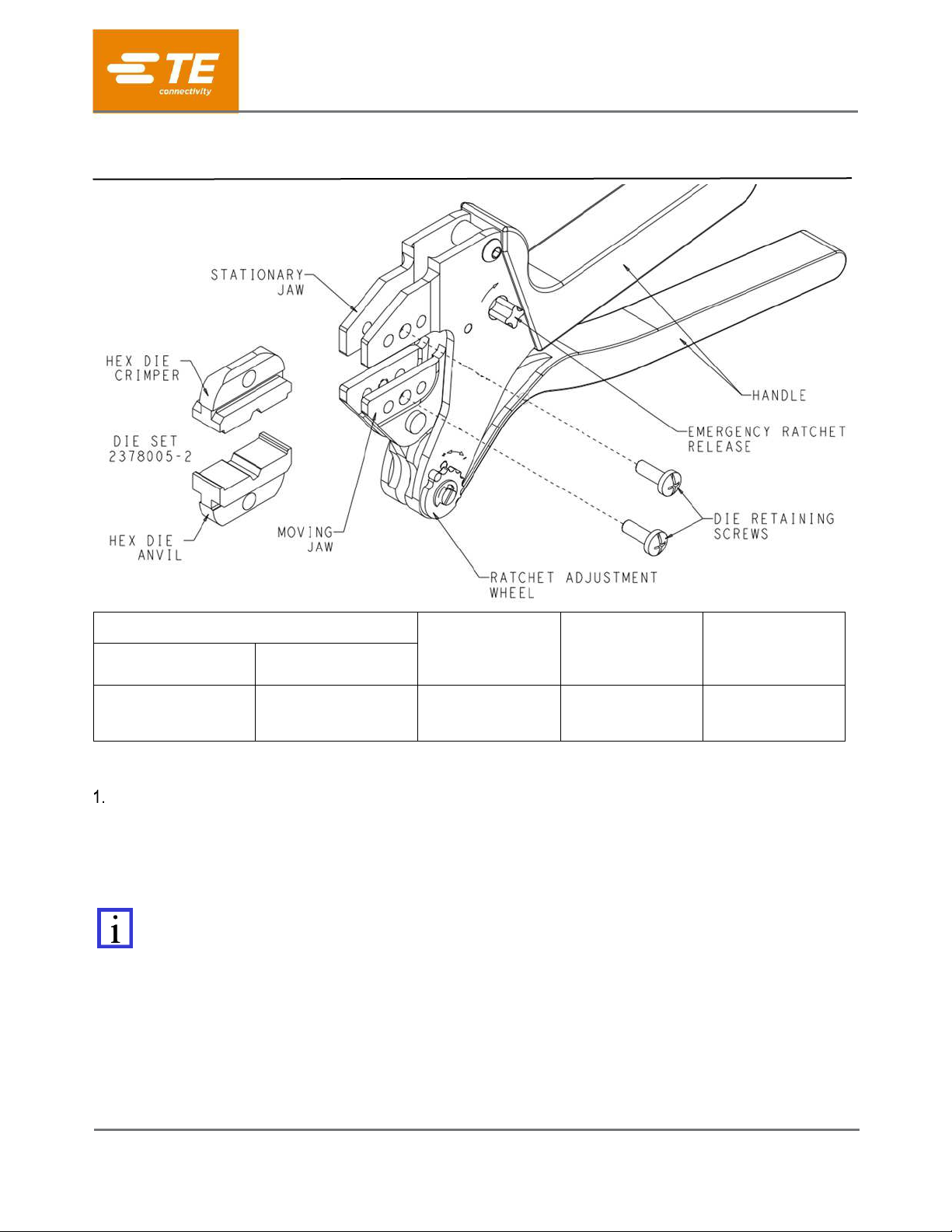
CRIMP TOOLING
TERMINAL P/N
FERRULE P/N
CABLE TYPE
SDE-SA TOOL
DIE ASSY ONLY
2378005-1
2378005-2
2311484-3
2311485-3
2311486-3
RTK 031
Figure 1.
INTRODUCTION
SDE-SA Commercial Hand Tool Assembly 2378005-1 for the FAKRA-HF straight plug and straight jack consist
of the tool and die set shown in Figure1. The tool consists of the SDE-SA Frame Assembly 9-1478240-0
(Instruction Sheet 408-8851) and the die assembly listed in Figure 1. This tool is used to crimp the terminal part
numbers provided in the table in Figure 1.
NOTE
Dimensions in this instruction sheet are in millimeters with [inches in brackets]. Figures and illustrations are for
reference only and are not drawn to scale.
Read these instructions thoroughly before crimping connectors.
SDE-SA Commercial Hand Tool
Assembly; PN 2378005-1 with
Die Assembly PN 2378005-2
408-35125
Rev 1
2 of 5
DESCRIPTION
The tool frame features two jaws, a handle, ratchet adjustment wheel, and an emergency ratchet release. The
die set consist of a crimper (upper die) and an anvil (lower die). The tool frame holds a die assembly with one
or more crimping chambers. See Figure 1. Die retaining screws are used to secure the dies in the tool frame.
The tool features a ratchet and an adjustment wheel with a range of settings. The ratchet ensures that the tool
has completed the cycle and will not release until the handles have ben FULLY closed, unless the emergency
ratchet release is rotated to manually release the ratchet. The adjustment wheel controls the amount of handle
pressure exerted on the dies during the crimping procedure.
CAUTION
The dies bottom before the ratchet release. This feature ensures maximum tensile performance of the crimp. DO
NOT re-adjust the ratchet.
INSTALLATION AND REMOVAL OF DIE SET AND LOCATOR ASSEMBLY (FIGURE 1)
1. Open the tool handles and remove the two die retaining screws from the tool jaws.
2. Place the hex die anvil so that the marked surfaces face outward, when mounted in the moving jaw of
the tool frame.
3. Insert the die retaining screw through the jaw and through the hex die anvil and tighten the screw just
enough to hold the die in place. Do not tighten the screw completely at this time.
4. Place the hex die crimper so that the marked surface face outward, when mounted in the stationary jaw
of the tool frame.
5. Insert the die retaining screw through the jaw and through the hex die crimper and tighten the screw
just enough to hold the die in place. Do not tighten the screw completely at this time.
6. Carefully close the tool handles, making sure the anvil and crimper align properly. Continue closing the
tool handles until the ratchet in the tool frame has engaged sufficiently to hold the anvil and crimper in
place, then tighten both die retaining screws.
7. To disassemble, close the tool handles until the ratchet releases, remove the two die retaining screws,
and slide the anvil and crimper out of the tool jaws.
NOTE
The ratchet release has detents with audible “clicks” as the handles are closed. The ratchet releases on the sixth
“click”.
CRIMPING PROCEDURE
NOTE
The tool is provided with a crimp adjustment feature. Initially, the crimp height should be verified as specified in
Figure 4. Refer to Section 6, Crimp Height Inspection, and Section 7, Crimp Height Adjustment, to verify crimp
height before using the tool to crimp desired contacts and wire sizes.
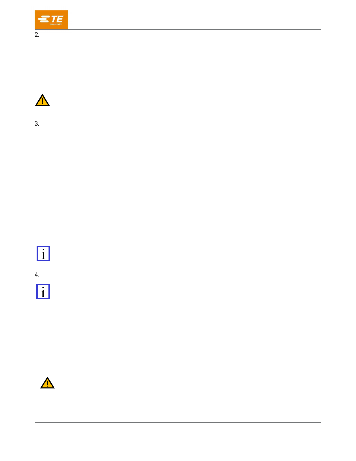
Refer to the table in Figure 1 and select wire of the specified type. Strip the wire to the length specified for the
connector. Do not nick or cut wire strands. Select the applicable contact and assemble according to the
manufacturer’s instructions. Refer to Figure 2 and proceed as follows:
1. Hold the tool so that the back (wire side) is facing you. Squeeze the tool handles together and allow
them to open fully.
2. Holding the contact assembly, insert the contact assembly through the front of the tool and into the
crimp section.
3. Position the contact assembly in the crimp section.
4. CAUTION
Make sure that both sides of the wire barrel are started evenly into the crimping section. DO NOT attempt to crimp
an improperly positioned contact.
5. While holding the contact assembly in place, fully cycle the tool until the ratchet releases and allows
the handle to open.
408-35125
Rev 1
3 of 5
Figure 2.
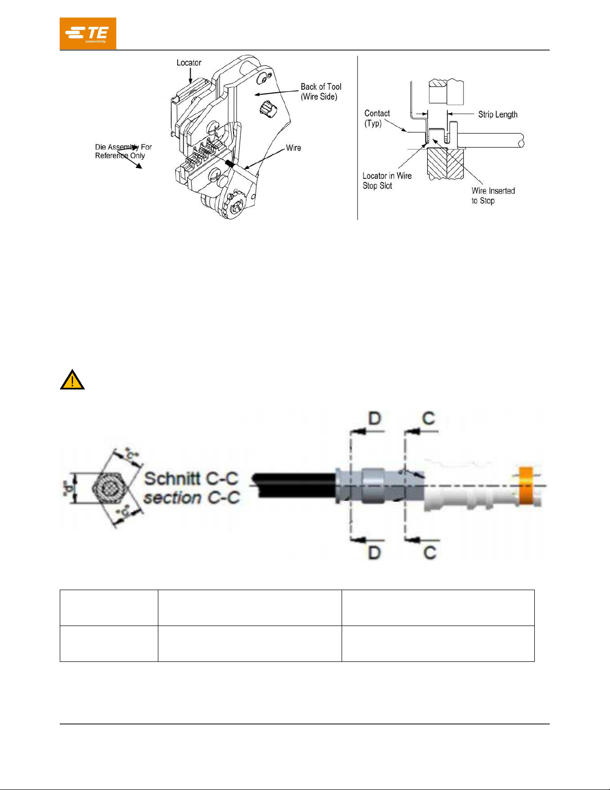
5. CRIMP HEIGHT INSPECTION
Crimp height inspection is performed using a micrometer with a modified anvil, commonly referred to as a
crimp-height comparator. TE Connectivity does not manufacture or market crimp height comparators. Detailed
information on obtaining and using crimp-height comparators can be found in Instruction Sheet 408-7424.
1. Refer to Figure 1 and select a wire (maximum size) for each crimp section listed.
2. Refer to Section 4, CRIMPING PROCEDURE, and crimp the contacts accordingly.
3. Using a crimp height comparator, measure the wire barrel crimp height listed in Figure 4. If the crimp
height conforms to that shown in the table, the tool is considered dimensionally correct. If not, the tool
must be adjusted. Refer to Section 7, RATCHET (CRIMP HEIGHT) ADJUSTMENT.
CAUTION
Damaged product should not be used. If a damaged contact is evident, it should be replaced. Contacts must not
be re-terminated.
Figure 4.
TOOLING
CRIMP HEIGHT
SECTION “c”
CRIMP HEIGHT
SECTION “d”
2378005-1
2378005-2
(4.3 ± 0.05)
4.3 ± 0.05
408-35125
Rev 1
4 of 5
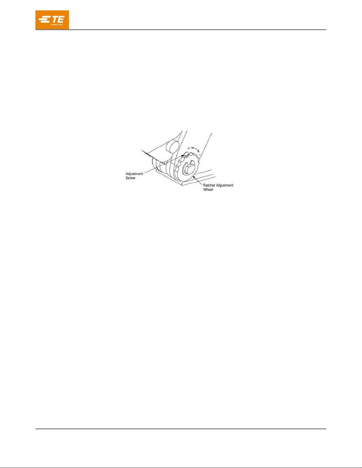
6. RATCHET (CRIMP HEIGHT) ADJUSTMENT (Figure 5.)
Although the ratchet is preset prior to shipment, it is important to verify the crimp height using a micrometer or
caliper. General use and subsequent wear may cause the tool to go out of adjustment. It is recommended that
crimp height be inspected, and the ratchet be adjusted, if necessary, on a regular basis. Refer to Figure 4, and
proceed as follows:
1. If the crimp height is larger than recommended, remove the ratchet wheel adjustment screw and rotate
the adjustment wheel counterclockwise (+) to a higher setting. Reinstall the screw. Repeat as required.
2. If the crimp height is smaller than recommended, remove the ratchet wheel adjustment screw and
rotate the adjustment wheel clockwise (-) to a lower setting. Reinstall the screw. Repeat as required.
3. If the crimp height cannot be made to conform to the recommended crimp height, the tool or die set
must be replaced. See Section 9, REPLACEMENT.
Figure 5.
7. MAINTENANCE AND INSPECTION
7.1. Maintenance
1. Remove dust, moisture, and other contaminants with a clean soft brush or soft lint free cloth. DO NOT
use objects that could damage the dies or tool.
2. When the tool is not in use, keep the handles closed to prevent objects from becoming lodged in the
dies. Store the tool in a clean dry area.
3. Remove all lubrication and accumulated film from the dies by immersing the dies in a suitable
commercial degreaser.
7.2. Visual Inspection
1. Inspection of the tool and dies should be made on a regular basis to ensure they have not become
worn or damaged.
2. Make sure the die retaining screws are properly secured.
3. Inspect the crimping chambers of the die assembly for flattened, chipped, worn, or broken areas. If
damage or abnormal wear is evident, the dies must be replaced. Refer to section 9.
8. REPLACEMENT
If the dies are damaged or worn excessively, they must be replaced.
Order dies through your TE representative, or call 1-800-522-6752, or send a facsimile of your purchase order
to 717-986-7605, or write to:
CUSTOMER SERVICE (038-035)
TE CONNECTIVITY CORPORATION
PO BOX 3608
HARRISBURG PA 17105-3608
Call 1-800-522-6752 for customer repair services.

408-35125
Rev 1
5 of 5
9. REVISION SUMMARY
Revisions to this instruction sheet include:
Initial release of this document.
Table of contents


