Makita DJN160RFJ User manual

GB Cordless Nibbler Instruction Manual
F Grignoteuse Sans Fil Manuel d’instructions
D Akku-Knabber Betriebsanleitung
I Roditrice a batteria Istruzioni per l’uso
NL
Snoerloze knabbelschaar
Gebruiksaanwijzing
E Roedora Inalámbrica Manual de instrucciones
P Tesoura Punção a Bateria Manual de instruções
DK Akku-pladestanser Brugsanvisning
GR Ζουμποψάλιδο μπαταρίας Οδηγίες χρήσεως
TR Akülü Nibler Kullanma kılavuzu
DJN160
DJN161

2
12
34
56
78
4
17
18
19 16
7
20
5
14
15 16
13
12
9
10
11
1
2
3
5
67
8
013273 012128
013275 004775
013276 013277
004779 013274

3
910
11 12
13
15
14
17
5
21
22
23
24
25
004782
013278 013279
013280
17
11
004781

4
14 15
16 17
24 26
27
28 11
29
30
29
004791 001145
013281 013282

5
ENGLISH (Original instructions)
Explanation of general view
1 Button
2 Red indicator
3 Battery cartridge
4 Star marking
5 Die holder
6 Lock nut
7 Loosen
8Wrench
9 Gauge for cutting stainless:
1.2 mm (3/64")
10 Gauge for cutting mild steel:
1.6 mm (1/16")
11 Notch
12 Slide switch
13 Indicating lamp
14 Die
15 Bolts
16 Hex wrench
17 Punch
18 Punch holder
19 Screw
20 Tighten
21 From the top view
22 Cutting at an angle to grooves
23 Cutting perpendicular to
grooves
24 From the side view
25 Corrugated or trapezoidal sheet
metal
26 Cutting head should be at a
right angle (90°) to cutting sur-
face.
27 Limit mark
28 Holder cap cover
29 Screwdriver
30 Brush holder cap
SPECIFICATIONS
• Due to our continuing program of research and devel-
opment, the specifications herein are subject to change
without notice.
• Specifications and battery cartridge may differ from
country to country.
• Weight, with battery cartridge, according to EPTA-Pro-
cedure 01/2003
ENE037-1
Intended use
The tool is intended for cutting sheet steel and stainless
sheet steel.
GEA010-1
General Power Tool Safety Warnings
WARNING Read all safety warnings and all
instructions. Failure to follow the warnings and
instructions may result in electric shock, fire and/or
serious injury.
Save all warnings and instructions for future
reference.
GEB028-2
NIBBLER SAFETY WARNINGS
1. Hold the tool firmly.
2. Secure the workpiece firmly.
3. Keep hands away from moving parts.
4. Edges and chips of the workpiece are sharp.
Wear gloves. It is also recommended that you
put on thickly bottomed shoes to prevent injury.
5. Do not put the tool on the chips of the work-
piece. Otherwise it can cause damage and trou-
ble on the tool.
6. Do not leave the tool running. Operate the tool
only when hand-held.
7. Always be sure you have a firm footing.
Be sure no one is below when using the tool in
high locations.
8. Do not touch the punch, die or the workpiece
immediately after operation; they may be
extremely hot and could burn your skin.
9. Avoid cutting electrical wires. It can cause seri-
ous accident by electric shock.
SAVE THESE INSTRUCTIONS.
WARNING:
DO NOT let comfort or familiarity with product
(gained from repeated use) replace strict adherence
to safety rules for the subject product. MISUSE or
failure to follow the safety rules stated in this instruc-
tion manual may cause serious personal injury.
Model DJN160 DJN161
Max. cutting capacities
Steel up to 400 N/mm21.6 mm/16 ga 1.6 mm/16 ga
Steel up to 600 N/mm21.2 mm/18 ga 1.2 mm/18 ga
Aluminum up to 200 N/mm22.5 mm/12 ga 2.5 mm/12 ga
Min. cutting radius Outside edge 50 mm 50 mm
Inside edge 45 mm 45 mm
Strokes per minute (min–1) 1,900 1,900
Overall length 313 mm 313 mm
Net weight 2.1 kg 2.2 kg
Rated voltage D.C. 14.4 V D.C. 18 V

6
ENC007-8
IMPORTANT SAFETY INSTRUCTIONS
FOR BATTERY CARTRIDGE
1. Before using battery cartridge, read all instruc-
tions and cautionary markings on (1) battery
charger, (2) battery, and (3) product using bat-
tery.
2. Do not disassemble battery cartridge.
3. If operating time has become excessively
shorter, stop operating immediately. It may
result in a risk of overheating, possible burns
and even an explosion.
4. If electrolyte gets into your eyes, rinse them out
with clear water and seek medical attention right
away. It may result in loss of your eyesight.
5. Do not short the battery cartridge:
(1) Do not touch the terminals with any conduc-
tive material.
(2) Avoid storing battery cartridge in a con-
tainer with other metal objects such as nails,
coins, etc.
(3) Do not expose battery cartridge to water or
rain.
A battery short can cause a large current flow,
overheating, possible burns and even a break-
down.
6. Do not store the tool and battery cartridge in
locations where the temperature may reach or
exceed 50°C (122°F).
7. Do not incinerate the battery cartridge even if it
is severely damaged or is completely worn out.
The battery cartridge can explode in a fire.
8. Be careful not to drop or strike battery.
9. Do not use a damaged battery.
10. Follow your local regulations relating to disposal
of battery.
SAVE THESE INSTRUCTIONS.
Tips for maintaining maximum battery life
1. Charge the battery cartridge before completely
discharged.
Always stop tool operation and charge the bat-
tery cartridge when you notice less tool power.
2. Never recharge a fully charged battery cartridge.
Overcharging shortens the battery service life.
3. Charge the battery cartridge with room tempera-
ture at 10°C – 40°C (50°F – 104°F). Let a hot bat-
tery cartridge cool down before charging it.
4. Charge the battery cartridge once in every six
months if you do not use it for a long period of
time.
FUNCTIONAL DESCRIPTION
CAUTION:
• Always be sure that the tool is switched off and the bat-
tery cartridge is removed before adjusting or checking
function on the tool.
Installing or removing battery cartridge (Fig. 1)
CAUTION:
• Always switch off the tool before installing or removing
of the battery cartridge.
•Hold the tool and the battery cartridge firmly when
installing or removing battery cartridge. Failure to
hold the tool and the battery cartridge firmly may cause
them to slip off your hands and result in damage to the
tool and battery cartridge and a personal injury.
To remove the battery cartridge, slide it from the tool
while sliding the button on the front of the cartridge.
To install the battery cartridge, align the tongue on the
battery cartridge with the groove in the housing and slip it
into place. Insert it all the way until it locks in place with a
little click. If you can see the red indicator on the upper
side of the button, it is not locked completely.
CAUTION:
• Always install the battery cartridge fully until the red
indicator cannot be seen. If not, it may accidentally fall
out of the tool, causing injury to you or someone
around you.
• Do not install the battery cartridge forcibly. If the car-
tridge does not slide in easily, it is not being inserted
correctly.
Battery protection system (Fig. 2)
The tool is equipped with a battery protection system.
This system automatically cuts off power to the motor to
extend battery life.
The tool will automatically stop during operation if the
tool and/or battery are placed under one of the following
conditions:
• Overloaded:
The tool is operated in a manner that causes it to draw
an abnormally high current.
In this situation, turn the tool off and stop the applica-
tion that caused the tool to become overloaded. Then
turn the tool on to restart.
If the tool does not start, the battery is overheated. In
this situation, let the battery cool before turning the tool
on again.
• Low battery voltage:
The remaining battery capacity is too low and the tool
will not operate. In this situation, remove and recharge
the battery.
NOTE:
• The overheat protection works only with a battery car-
tridge with a star mark.
Changing the die position (Fig. 3)
The die holder position can be changed 360°. To change
it, proceed as follows.
1. Loosen the lock nut with the wrench provided.
2. Pull the die holder slightly and turn it to the desired
position for operation.
3. Tighten the lock nut to secure the die holder in the
desired position.
There are four positive stops at 90° each: 0°, 90° left and
right and 180°. To position the die to any of these positive
stops:
4. Loosen the lock nut with the wrench provided.
5. Pull the die holder slightly and depress lightly while
turning it to the desired position. The die holder will
lock into one of the positive stop positions as desired.
6. Turn the die holder slightly to make sure that it is posi-
tively locked into position.
7. Tighten the lock nut to secure the die holder.

7
Permissible cutting thickness (Fig. 4)
The thickness of material to be cut depends upon the
tensile strength of the material itself. The groove on the
die holder acts as a thickness gauge for allowable cutting
thickness. Do not attempt to cut any material which will
not fit into this groove.
Cutting line
The notch in the die holder indicates your cutting line. Its
width is equal to the cutting width. Align the notch to the
cutting line on the workpiece when cutting.
Switch action (Fig. 5)
CAUTION:
• Before inserting the battery cartridge into the tool,
always check to see that the slide switch actuates
properly and returns to the “OFF” position when the
rear of the slide switch is depressed.
• Switch can be locked in “ON” position for ease of oper-
ator comfort during extended use. Apply caution when
locking tool in “ON” position and maintain firm grasp on
tool.
To start the tool, slide the slide switch toward the “I (ON)”
position. For continuous operation, press the front of the
slide switch to lock it.
To stop the tool, press the rear of the slide switch, then
slide it toward the “O (OFF)” position.
Indication lamp with multi function (Fig. 6)
Indication lamps are located in two positions.
- Battery cartridge replacing signal
- When the battery power is almost used up during
operation, the red lamp lights up and the tool stops
immediately. Replace the battery with fully charged
one when the red lamp lights up.
- Accidental re-start preventive function
- Even if the battery cartridge is inserted on the tool
with the slide switch in the “I (ON)” position, the tool
does not start. At this time, the lamp flickers slowly
and this shows that the accidental re-start preventive
function is at work.
- To start the tool, first slide the slide switch toward the
“O (OFF)” position and then slide it toward the “I
(ON)” position.
ASSEMBLY
CAUTION:
• Always be sure that the tool is switched off and the bat-
tery cartridge is removed before carrying out any work
on the tool.
Removing or installing the punch and die (Fig. 7,
8, 9 & 10)
Always replace the punch and die as a set. To remove
the punch and die, loosen the lock nut with the wrench.
Remove the die holder from the tool. Use the hex wrench
to loosen the bolts which secure the die. Remove the die
from the die holder.
Use the hex wrench to loosen the screw which secures
the punch. Pull the punch out of the punch holder.
To install the punch and die, insert the punch into the
punch holder so that the notch in the punch faces toward
the screw. Tighten the screw to secure the punch. Install
the die on the die holder. Tighten the bolts to secure the
die.
Then install the die holder on the tool so that the punch is
inserted through the hole in the die holder. Tighten the
lock nut to secure the die holder. After replacing the
punch and die, lubricate them with machine oil and run
the tool for a while.
OPERATION
Pre-lubrication
Coat the cutting line with machine oil to increase the
punch and die service life. This is particularly important
when cutting aluminum.
Cutting method (Fig. 11)
Hold the tool so that the cutting head is at a right angle
(90°) to the workpiece being cut. Move the tool gently in
the cutting direction.
Cutouts (Fig. 12)
Cutouts can be done by first opening a round hole over
21 mm in diameter which the cutting head can be
inserted into.
Cutting the corrugated or trapezoidal sheet
metals (Fig. 13 & 14)
Set the die position so that the die faces the cutting direc-
tion either when cutting at an angle or perpendicular go
grooves in corrugated or trapezoidal sheet metals.
Always hold the tool body parallel to the grooves with the
cutting head at a right angle (90°) to the cutting surface
as shown in the figure.
MAINTENANCE
CAUTION:
• Always be sure that the tool is switched off and the bat-
tery cartridge is removed before attempting to perform
inspection or maintenance.
• Never use gasoline, benzine, thinner, alcohol or the
like. Discoloration, deformation or cracks may result.
Replacing carbon brushes (Fig. 15, 16 & 17)
Remove and check the carbon brushes regularly.
Replace when they wear down to the limit mark. Keep
the carbon brushes clean and free to slip in the holders.
Both carbon brushes should be replaced at the same
time. Use only identical carbon brushes.
Insert the top end of slotted bit screwdriver into the notch
in the tool and remove the holder cap cover by lifting it
up.
Use a screwdriver to remove the brush holder caps. Take
out the worn carbon brushes, insert the new ones and
secure the brush holder caps.
Reinstall the holder cap cover on the tool.
To maintain product SAFETY and RELIABILITY, repairs,
any other maintenance or adjustment should be per-
formed by Makita Authorized Service Centers, always
using Makita replacement parts.

8
OPTIONAL ACCESSORIES
CAUTION:
• These accessories or attachments are recommended
for use with your Makita tool specified in this manual.
The use of any other accessories or attachments might
present a risk of injury to persons. Only use accessory
or attachment for its stated purpose.
If you need any assistance for more details regarding
these accessories, ask your local Makita Service Center.
• Die
•Punch
• Hex wrench
• Wrench 32
• Makita genuine battery and charger
NOTE:
• Some items in the list may be included in the tool pack-
age as standard accessories. They may differ from
country to country.
ENG905-1
Noise
The typical A-weighted noise level determined according
to EN60745:
Model DJN160
Sound pressure level (LpA): 72 dB(A)
Uncertainty (K): 3 dB(A)
The noise level under working may exceed 80 dB (A).
Model DJN161
Sound pressure level (LpA): 73 dB(A)
Uncertainty (K): 3 dB(A)
The noise level under working may exceed 80 dB (A).
Wear ear protection
ENG900-1
Vibration
The vibration total value (tri-axial vector sum) determined
according to EN60745:
Model DJN160
Work mode: cutting sheet metal
Vibration emission (ah): 7.0 m/s2
Uncertainty (K): 1.5 m/s2
Model DJN161
Work mode: cutting sheet metal
Vibration emission (ah): 6.5 m/s2
Uncertainty (K): 1.5 m/s2
ENG901-1
• The declared vibration emission value has been mea-
sured in accordance with the standard test method and
may be used for comparing one tool with another.
• The declared vibration emission value may also be
used in a preliminary assessment of exposure.
WARNING:
• The vibration emission during actual use of the power
tool can differ from the declared emission value
depending on the ways in which the tool is used.
• Be sure to identify safety measures to protect the oper-
ator that are based on an estimation of exposure in the
actual conditions of use (taking account of all parts of
the operating cycle such as the times when the tool is
switched off and when it is running idle in addition to
the trigger time).
ENH101-16
For European countries only
EC Declaration of Conformity
We Makita Corporation as the responsible
manufacturer declare that the following Makita
machine(s):
Designation of Machine:
Cordless Nibbler
Model No./ Type: DJN160, DJN161
are of series production and
Conforms to the following European Directives:
2006/42/EC
And are manufactured in accordance with the following
standards or standardised documents:
EN60745
The technical documentation is kept by:
Makita International Europe Ltd.
Technical Department,
Michigan Drive, Tongwell,
Milton Keynes, Bucks MK15 8JD, England
26.4.2012
Tomoyasu Kato
Director
Makita Corporation
3-11-8, Sumiyoshi-cho,
Anjo, Aichi, 446-8502, JAPAN

24
NEDERLANDS (Originele instructies)
Verklaring van algemene gegevens
1 Knop
2 Rode indicator
3Accu
4 Stermarkering
5 Meshouder
6 Borgmoer
7 Loszetten
8 Sleutel
9 Diktemaat voor roestvrij staal:
1,2 mm (3/64")
10 Diktemaat voor zacht staal:
1,6 mm (1/16")
11 Inkeping
12 Stroomschakelaar
13 Werkingslampje
14 Mes
15 Bouten
16 Zeskant-inbussleutel
17 Drevel
18 Drevelhouder
19 Schroef
20 Vastdraaien
21 Bovenaanzicht
22 Schuin op de groeven snijden
23 Haaks op de groeven snijden
24 Zijaanzicht
25 Gegolfde of trapezoïdale
metaalplaat
26 De snijkop moet een rechte
hoek (90°) maken met het te
snijden oppervlak.
27 Limietmarkering
28 Kap van de borstelhouderdop
29 Schroevendraaier
30 Borstelhouderdop
TECHNISCHE GEGEVENS
• Vanwege ons voortgaand onderzoeks- en
ontwikkelingsprogramma kunnen de bijgaande
technische gegevens zonder voorafgaande
kennisgeving worden gewijzigd.
• De technische gegevens en de accu kunnen van land
tot land verschillen.
• Gewicht, inclusief accu, volgens de EPTA-procedure
01/2003
ENE037-1
Doeleinden van gebruik
Dit gereedschap is bedoeld voor het knippen van
staalplaat en roestvrijstaalplaat.
GEA010-1
Algemene veiligheidswaarschuwingen voor
elektrisch gereedschap
WAARSCHUWING! Lees alle
veiligheidswaarschuwingen en alle instructies. Het
niet volgen van de waarschuwingen en instructies kan
leiden tot elektrische schokken, brand en/of ernstig
letsel.
Bewaar alle waarschuwingen en instructies om in de
toekomst te kunnen raadplegen.
GEB028-2
VEILIGHEIDSVOORSCHRIFTEN VOOR DE
KNABBELSCHAAR
1. Houd het gereedschap stevig vast.
2. Zet het werkstuk goed vast.
3. Houd uw handen uit de buurt van bewegende
onderdelen.
4. De randen en afgeknipte spaanders van het
werkstuk zijn uiterst scherp. Draag
handschoenen. Draag bij voorkeur ook
schoenen met dikke zolen, om mogelijke
verwondingen te voorkomen.
5. Plaats het gereedschap niet op de afgeknipte
spaanders van het werkstuk. Dit kan
beschadiging en defect van het gereedschap
veroorzaken.
6. Laat het gereedschap niet achter terwijl het nog
in bedrijf is. Laat het gereedschap alleen draaien
terwijl u het met de handen vasthoudt.
7. Zorg ervoor dat u altijd stevige steun voor de
voeten hebt.
Controleer of er zich niemand beneden u bevindt
wanneer u het gereedschap op een hoge plaats
gaat gebruiken.
8. Raak de stempel, de matrijs of het werkstuk niet
onmiddellijk na gebruik aan. Zij kunnen
bijzonder heet zijn en brandwonden op uw huid
veroorzaken.
Model DJN160 DJN161
Maximale snijcapaciteit
Staal tot maximaal 400 N/mm21,6 mm/16 ga 1,6 mm/16 ga
Staal tot maximaal 600 N/mm21,2 mm/18 ga 1,2 mm/18 ga
Aluminium tot maximaal
200 N/mm22,5 mm/12 ga 2,5 mm/12 ga
Minimale snijcirkel Buitenrand 50 mm 50 mm
Binnenrand 45 mm 45 mm
Aantal snijbewegingen per minuut (min–1) 1 900 1 900
Totale lengte 313 mm 313 mm
Nettogewicht 2,1 kg 2,2 kg
Nominale spanning D.C. 14,4 V D.C. 18 V

25
9. Pas op dat u niet in elektrische draden snijdt. Dit
kan een ernstig ongeluk door elektrische schok
veroorzaken.
BEWAAR DEZE VOORSCHRIFTEN.
WAARSCHUWING:
LAAT NIET uw vertrouwdheid met het gereedschap
(na regelmatig gebruik) omslaan in slordigheid of
onachtzaamheid omtrent de strikt na te leven
veiligheidsvoorschriften voor dit product.
VERKEERD GEBRUIK of het niet naleven van de
veiligheidsvoorschriften in deze gebruiksaanwijzing
kan leiden tot ernstige verwondingen.
ENC007-8
BELANGRIJKE
VEILIGHEIDSVOORSCHRIFTEN
VOOR DE ACCU
1. Lees alle voorschriften en waarschuwingen op
(1) de acculader, (2) de accu, en (3) het product
waarvoor de accu wordt gebruikt, aandachtig
door alvorens de acculader in gebruik te nemen.
2. Neem de accu niet uit elkaar.
3. Als de gebruiksduur van het gereedschap erg
kort is geworden, staakt u dan onmiddellijk het
gebruik. Er bestaat kans op oververhitting, met
gevaar voor brand of zelfs een explosie.
4. Als er accuvloeistof in uw ogen komt, wast u die
dan onmiddellijk uit met volop water en
raadpleeg dan onverwijld een arts. Uw
gezichtsvermogen zou ernstig aangetast kunnen
worden.
5. Voorkom kortsluiting van de accu:
(1) Raak de accuklemmen nooit aan met een
geleidend materiaal.
(2) Bewaar de accu niet in een bak waarin
andere metalen voorwerpen zoals spijkers,
munten e.d. worden bewaard.
(3) Stel de accu niet bloot aan water of regen.
Kortsluiting van de accu kan oorzaak zijn van
een grote stroomafgifte, oververhitting,
brandwonden, en zelfs defecten.
6. Bewaar het gereedschap en de accu niet op een
plaats waar de temperatuur tot 50°C of hoger kan
oplopen.
7. Werp de accu nooit in het vuur, ook niet wanneer
hij zwaar beschadigd of volledig versleten is. De
accu kan namelijk ontploffen in het vuur.
8. Wees voorzichtig dat u de accu niet laat vallen
en hem niet blootstelt aan schokken of stoten.
9. Gebruik nooit een beschadigde accu.
10. Volg bij het wegwerpen van de accu de
plaatselijk geldende voorschriften.
BEWAAR DEZE VOORSCHRIFTEN.
Tips voor een maximale levensduur van de accu
1. Laad de accu op voordat hij volledig ontladen is.
Stop het gebruik van het gereedschap en laad de
accu op telkens wanneer u vaststelt dat het
vermogen van het gereedschap is afgenomen.
2. Laad een volledig opgeladen accu nooit opnieuw
op.
Als u de accu te veel oplaadt, zal hij minder lang
meegaan.
3. Laad de accu op bij een kamertemperatuur van
10°C – 40°C. Laat een warme accu afkoelen
alvorens hem op te laden.
4. Laad de accu zeker elk half jaar een keer op, ook
als u deze geruime tijd lang niet gebruikt.
BESCHRIJVING VAN DE FUNCTIES
LET OP:
• Zorg altijd dat het gereedschap is uitgeschakeld en de
accu ervan is verwijderd alvorens de functies op het
gereedschap af te stellen of te controleren.
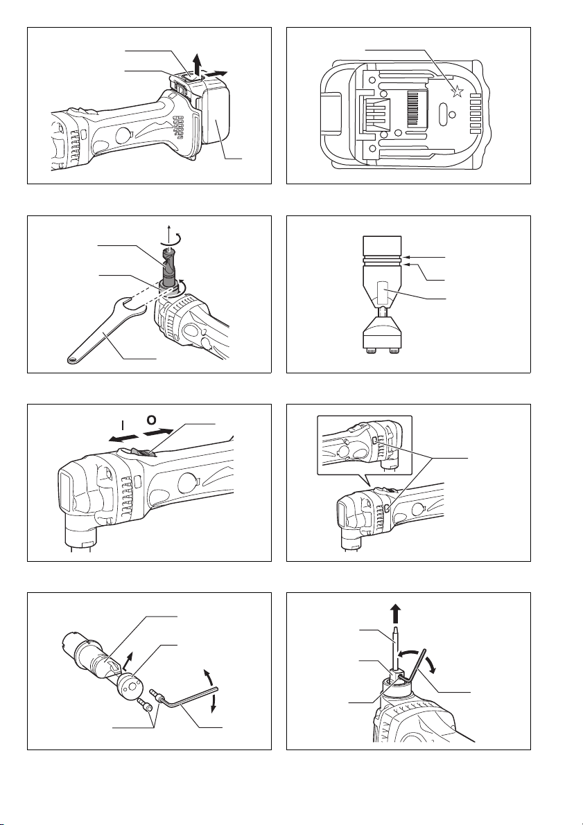
Aanbrengen en verwijderen van de accu (Fig. 1)
LET OP:
• Schakel altijd het gereedschap uit voordat u de accu
aanbrengt of verwijdert.
•Houd het gereedschap en de accu stevig vast
wanneer u de accu aanbrengt of verwijdert. Als u
het gereedschap en de accu niet stevig vasthoudt, zou
er iets uit uw handen kunnen glippen, met gevaar voor
schade aan het gereedschap of de accu en eventuele
verwonding.
Om de accu te verwijderen, schuift u deze uit het
gereedschap los terwijl u de knop voorop de accu
ingedrukt houdt.
Voor het aanbrengen van de accu plaatst u de tong van
de accu in de groef van de behuizing en schuift u de
accu op zijn plaats. Schuif de accu er altijd volledig in
totdat die op zijn plaats vast klikt. Wanneer de rode
indicator op de bovenkant van de knop nog zichtbaar is,
zit de accu niet volledig erin.
LET OP:
• Schuif de accu volledig erin totdat de rode indicator niet
meer zichtbaar is. Als u dit nalaat, zou de accu uit het
gereedschap kunnen vallen en uzelf of anderen
kunnen verwonden.
• Druk de accu er niet met kracht in. Als de accu er niet
soepel in gaat, houdt u die waarschijnlijk in de
verkeerde stand.
Accubeveiligingssysteem (Fig. 2)
Het gereedschap is voorzien van een
accubeveiligingssysteem. Dit systeem kan automatisch
de stroomtoevoer naar de motor afsluiten om de
levensduur van de accu te verlengen.
Het gereedschap kan tijdens gebruik automatisch
stoppen wanneer het gereedschap en/of de accu aan
één van de volgende omstandigheden wordt
blootgesteld:
• Overbelasting:
Als het gereedschap wordt gebruikt op een manier die
een abnormaal hoge stroomsterkte vergt.
In dat geval schakelt u het gereedschap uit en verhelpt
u de oorzaak van de overbelasting nadat het werktuig
gestopt is. Dan schakelt u het gereedschap weer in om
het te herstarten.
Als het gereedschap niet start, kan de accu oververhit
zijn. In dat geval laat u de accu afkoelen voordat u het
gereedschap opnieuw inschakelt.
• Onvoldoende accuspanning:
Als de resterende accuspanning onvoldoende is, zal
het gereedschap niet starten. In dat geval verwijdert u
de accu en laadt u die opnieuw op.

26
OPMERKING:
• De beveiliging tegen oververhitting werkt alleen bij
accu's met een stermarkering.
Stand van het mes wijzigen (Fig. 3)
De stand van de meshouder is 360° draaibaar. Om de
stand te wijzigen, gaat u als volgt te werk.
1. Draai de borgmoer los met de bijgeleverde sleutel.
2. Trek de meshouder ietwat omhoog en draai die dan in
de gewenste stand voor het werk.
3. Draai de borgmoer weer vast om de meshouder in de
gekozen stand te vergrendelen.
Er zijn vier vaste klikstanden met 90° er tussen: Bij 0°,
90° links en rechts en 180°. Om het mes in te stellen op
één van deze vaste klikstanden:
4. Draai de borgmoer los met de bijgeleverde sleutel.
5. Trek de meshouder iets omhoog en druk hem dan
licht omlaag terwijl u de meshouder naar de gewenste
stand draait. De meshouder zal in de door u gekozen
klikstand vastklikken.
6. Draai lichtjes aan de meshouder om te controleren dat
hij stevig vastzit.
7. Draai de borgmoer vast om de meshouder te
vergrendelen.
Toegestane snijdikte (Fig. 4)
De dikte van het te snijden materiaal hangt af van de
treksterkte van het materiaal zelf. De groef in de
meshouder dient als diktemaat voor de toegestane
snijdikte. Probeer geen materiaal te snijden dat niet in
deze groef past.
Kniplijn
De inkeping in de meshouder geeft de snijlijn aan. De
breedte ervan komt overeen met de snijbreedte. Laat bij
het snijden de inkeping samenvallen met de snijlijn op
het werkstuk.
Schakelaarwerking (Fig. 5)
LET OP:
• Alvorens de accu in het gereedschap te plaatsen, moet
u controleren of de schuifschakelaar correct
functioneert en terugkeert in de “UIT”-stand wanneer
de achterkant van de schakelaar wordt ingedrukt.
• De schakelaar kan in de “AAN”-stand vergrendeld
worden, hetgeen bij langdurig gebruik comfortabeler
werkt. Wees extra voorzichtig wanneer u de schakelaar
in de “AAN”-stand vergrendelt en houd het
gereedschap altijd stevig vast.
Om het gereedschap te starten, schuift u de
stroomschakelaar in de “I (AAN)”-stand. Voor continu
gebruik drukt u de voorkant van de stroomschakelaar in,
om die te vergrendelen.
Om het gereedschap te stoppen drukt u op de achterkant
van de stroomschakelaar en schuift u die naar de “O
(UIT)”-stand.
Werkingslampje met diverse functies (Fig. 6)
Op twee plaatsen is voorzien in een werkingslampje.
- Aanduiding voor vervangen van de accu
- Wanneer tijdens het gebruik de accu bijna helemaal
leeg is, gaat het rode lampje branden en stopt het
gereedschap onmiddellijk. Wanneer het rode lampje
oplicht, vervangt u de accu door één die volledig is
opgeladen.
- Beveiliging tegen per ongeluk herstarten
- Al staat de schuifschakelaar nog in de “I (AAN)”-
stand wanneer u een accu in het apparaat plaatst,
het gereedschap zal dan niet starten. In dat geval
knippert het lampje langzaam om aan te geven dat
de beveiliging tegen per ongeluk herstarten in
werking is getreden.
- Om dan het gereedschap te starten, schuift u eerst
de schakelaar naar de “O (UIT)”-stand en dan schuift
u die weer in de “I (AAN)”-stand.
INEENZETTEN
LET OP:
• Controleer altijd of het gereedschap is uitgeschakeld
en de accu ervan is verwijderd alvorens enig werk aan
het gereedschap uit te voeren.
De drevel en het mes verwijderen of aanbrengen
(Fig. 7, 8, 9 en 10)
Vervang de drevel en het mes altijd samen. Om de
drevel en het mes te vervangen, draait u de borgmoer los
met de sleutel. Verwijder de meshouder van het
gereedschap. Draai de mesbevestigingsbouten los met
behulp van de zeskant-inbussleutel. Verwijder het mes
uit de meshouder.
Draai de drevelbevestigingsschroef los met behulp van
de inbussleutel. Trek de drevel uit de drevelhouder.
Om de drevel en het mes aan te brengen, steekt u de
drevel in de drevelhouder zodat de uitsparing in de
drevel naar de schroef toe wijst. Draai de schroef vast
om de drevel te vergrendelen. Plaats het mes in de
meshouder. Draai de bouten vast om het mes te
vergrendelen.
Bevestig vervolgens de meshouder op het gereedschap
zodat de drevel door de opening in de meshouder steekt.
Draai de borgmoer vast om de meshouder te
vergrendelen. Na het vervangen van de drevel en het
mes, smeert u ze met machineolie en laat u het
gereedschap een tijdje draaien.
BEDIENING
Voorsmering
Breng machineolie aan op de snijlijn voor een langere
levensduur van de drevel en het mes. Dit is met name
belangrijk bij het snijden van aluminium.
Snijmethode (Fig. 11)
Houd het gereedschap zo dat de snijkop een rechte hoek
(90°) maakt met het te snijden werkstuk. Beweeg het
gereedschap soepel en gelijkmatig in de snijrichting.
Uitsnijdingen (Fig. 12)
Om materiaal uit te snijden, maakt u eerst een
rondeopening met een diameter van meer dan 21 mm
waarin u dan de snijkop kunt steken.
Gegolfde of trapezoïdale metaalplaat snijden
(Fig. 13 en 14)
Stel het mes zo in dat het mes in de snijrichting wijst
wanneer schuin of haaks op de groeven in gegolfde of
trapezoïdale metaalplaat wordt gesneden.
Houd het gereedschap altijd parallel aan de groeven,
met de snijkop haaks (90°) op het snijvlak, zoals getoond
in de afbeelding.

27
ONDERHOUD
LET OP:
• Zorg er altijd voor dat het gereedschap is
uitgeschakeld en de accu is verwijderd, voordat u
enige inspectie of onderhoud uitvoert.
• Gebruik nooit benzine, wasbenzine, thinner, alcohol en
dergelijke. Hierdoor kunnen verkleuring, vervormingen
en barsten worden veroorzaakt.
Koolborstels vervangen (Fig. 15, 16 en 17)
Verwijder en controleer regelmatig de koolborstels.
Vervang de koolborstels wanneer ze tot aan de
limietmarkering versleten zijn. Houd de koolborstels
schoon, zodat ze gemakkelijk in de houders glijden.
Vervang altijd beide koolborstels tegelijk. Gebruik
uitsluitend identieke koolborstels.
Steek het uiteinde van een platte schroevendraaier in de
inkeping in het gereedschap en verwijder de kap van de
borstelhouderdop door die omhoog te wippen.
Gebruik een schroevendraaier om de kap van de
borstelhouderdoppen te verwijderen. Haal de versleten
koolborstels eruit, plaats de nieuwe erin en zet daarna de
doppen weer goed vast.
Breng de kap van de borstelhouderdop weer op het
gereedschap aan.
Om de VEILIGHEID en BETROUWBAARHEID van het
product te handhaven, dienen alle reparaties en alle
andere onderhoudswerkzaamheden of afstellingen te
worden uitgevoerd door een erkend Makita
Servicecentrum, en dat uitsluitend met gebruik van
Makita vervangingsonderdelen.
OPTIONELE ACCESSOIRES
LET OP:
• Deze accessoires of hulpstukken worden aanbevolen
voor gebruik met het Makita gereedschap dat in deze
gebruiksaanwijzing is beschreven. Bij gebruik van
andere accessoires of hulpstukken bestaat er gevaar
voor persoonlijke verwonding. Gebruik de accessoires
of hulpstukken uitsluitend voor hun bestemde doel.
Raadpleeg het dichtstbijzijnde Makita servicecentrum
voor verder advies of bijzonderheden omtrent deze
accessoires.
•Mes
• Drevel
• Zeskant-inbussleutel
• Sleutel 32
• Originele Makita accu en acculader
OPMERKING:
• Sommige onderdelen in deze lijst kunnen bij het
gereedschap zijn meeverpakt als standaard-
accessoires. Deze kunnen van land tot land
verschillen.
ENG905-1
Geluidsniveau
De typisch, A-gewogen geluidsniveaus vastgesteld
volgens EN60745:
Model DJN160
Geluidsdrukniveau (LpA): 72 dB(A)
Onnauwkeurigheid (K): 3 dB(A)
Tijdens het werken kan het geluidsniveau 80 dB (A)
overschrijden.
Model DJN161
Geluidsdrukniveau (LpA): 73 dB(A)
Onnauwkeurigheid (K): 3 dB(A)
Tijdens het werken kan het geluidsniveau 80 dB (A)
overschrijden.
Draag oorbeschermers
ENG900-1
Trilling
De totaalwaarde van de trillingen (triaxiale vectorsom)
vastgesteld volgens EN60745:
Model DJN160
Toepassing: knippen van metaalplaat
Trillingsemissie (ah) : 7,0 m/s2
Onnauwkeurigheid (K): 1,5 m/s2
Model DJN161
Toepassing: knippen van metaalplaat
Trillingsemissie (ah) : 6,5 m/s2
Onnauwkeurigheid (K): 1,5 m/s2
ENG901-1
• De opgegeven trillingsemissiewaarde is gemeten
volgens de standaardtestmethode en kan worden
gebruikt om dit gereedschap te vergelijken met andere
gereedschappen.
• De opgegeven trillingsemissiewaarde kan ook worden
gebruikt voor een beoordeling vooraf van de
blootstelling.
WAARSCHUWING:
• De trillingsemissie tijdens het gebruik van het elektrisch
gereedschap in de praktijk kan verschillen van de
opgegeven trillingsemissiewaarde afhankelijk van de
manier waarop het gereedschap wordt gebruikt.
• Zorg ervoor dat veiligheidsmaatregelen worden
getroffen ter bescherming van de operator die zijn
gebaseerd op een schatting van de blootstelling onder
praktijkomstandigheden (rekening houdend met alle
fasen van de bedrijfscyclus, zoals de tijdsduur
gedurende welke het gereedschap is uitgeschakeld en
stationair draait, naast de ingeschakelde tijdsduur).

28
ENH101-16
Alleen voor Europese landen
EU-Verklaring van Conformiteit
Wij, Makita Corporation, als de verantwoordelijke
fabrikant, verklaren dat de volgende Makita-
machine(s):
Aanduiding van de machine:
Snoerloze knabbelschaar
Modelnr./ Type: DJN160, DJN161
in serie zijn geproduceerd en
Voldoet aan de volgende Europese Richtlijnen:
2006/42/EU
En zijn gefabriceerd in overeenstemming met de
volgende normen of genormaliseerde documenten:
EN60745
De technische documentatie wordt bewaard door:
Makita International Europe Ltd.
Technische afdeling,
Michigan Drive, Tongwell,
Milton Keynes, Bucks MK15 8JD, Engeland
26.4.2012
Tomoyasu Kato
Directeur
Makita Corporation
3-11-8, Sumiyoshi-cho,
Anjo, Aichi, 446-8502, JAPAN

Makita Corporation
Anjo, Aichi, Japan
www.makita.com
885293-995
IDE
This manual suits for next models
5
Table of contents
Languages:
Other Makita Power Tools manuals

Makita
Makita HR2650 User manual

Makita
Makita TM30D User manual

Makita
Makita 4341CT User manual

Makita
Makita 3620 User manual

Makita
Makita XCM01 User manual

Makita
Makita DHR243 User manual

Makita
Makita TW004GZ01 User manual

Makita
Makita DFL650F User manual

Makita
Makita 6905B User manual

Makita
Makita XUX02 User manual

Makita
Makita DPP200 User manual

Makita
Makita AN621 User manual

Makita
Makita DJS200 User manual

Makita
Makita 6907D User manual

Makita
Makita DHR242 User manual

Makita
Makita HM1214C User manual

Makita
Makita 4340CT User manual

Makita
Makita BPJ140 User manual

Makita
Makita HM1400 User manual

Makita
Makita HR001G User manual