Etec EX350SS User manual

ETEC EX350SS
• Supports most 10” - 32” Flat Panel TVs
• Maximum weight capacity: 55 lbs.
2.2” to 8.4”
+5 to -15
For technical assistance or troubleshooting
please call 1-855-994-3832.
This product Wall Mount frame is intended for use only with an apparatus which has a maximum weight of 55 lbs. See apparatus
instructions. Using with an apparatus heavier than the maximum weight indicated may result in instability and cause possible
injury
READ THIS FIRST Read this entire manual! Do not attempt to install this product if you do not understand the instructions.
Contact a qualified mount installer if you have any doubts about a safe and secure mount installation, or if you are not sure what
specific wall materials you are attaching this mount to. Check all the parts carefully to make sure there are no missing or
damaged parts. Improper installation may result in damage to your TV, property, and personal injury.


Concrete Anchor
Ax2 Bx2 Cx2
N
EM4x30mm bolts
M5x12mm bolts
M6x12mm bolts
M4/M5 washers
M6/M8 washers
Socket tool
Allen wrench
F
M4x12mm bolts
D
M
I
J
M6x25mm bolts
M8x12mm bolts4
4
4
12
H
M8x25mm bolts
4
K
L
1
1
TV plate
2x1
Wall plate
1
Long Bolt Long Bolt washer

Use the selected bolts (D-J) and the washers (M-N) to install the TV Plate (2) to the rear of the TV
as shown below in Fig. 2. Tighten securely using the Allen wrench (K). Do not overtighten.
Fig. 2
K
1. Use the Allen wrench (K) to remove the two M6x12 Bolts and separate the Wall Plate (1) and
TV Plate (2) into two pieces as shown in Fig 1.
Step 1. Separate the TV Plate & Wall Plate
Step 2. Install the TV plate on the television.
12Fig. 1

5
Step 3. Find and mark the best position for the wall mount on the wall.
The best viewing height is parallel to the eye level of a person sitting on a couch. Normally, this is
about 4 feet above floor level.
In addition to your eye level height when you are seated, the following two measurements will help
you determine the perfect height for your wall-mounted television:
•The distance from your viewing location to the wall.
•The vertical distance from eye level to the floor plus the distance from your viewing location to the
wall when the viewing angle is 15 degrees.
For example:
• If distance ‘a’ is 5 to 7 feet (1.5 to 2.1 meters), distance ‘b’ is about 1 foot (0.3 meter)
• If distance ‘a’ is 8 to 13 feet (2.4 to 4 meters), distance ‘b’ is about 3 feet (0.9 meter)
• If distance ‘a’ is 14 to 17 feet (4.3 to 5.2 meters), distance ‘b’ is about 4 feet (1.2 meters)
Add the eye level height plus ‘b’ to get the ideal height of the center of the television display.

6
Step 4: Attach the wall mount to the wall
After determining the ideal height on the wall for your television, follow the mounting instructions for
your type of wall construction: wood stud walls or masonry walls (concrete, brick, or stone).
Do not use wall anchors in wood stud walls.
4. Use the Socket tool (L), the two Long Bolts (A), and Washers (C), to attach the wall mount to the wall.
Tighten the Long Bolts (A) securely and then loosen each bolt 1/2 turn. Shift the bottom of the wall
mount to insure the mount is perfectly level. Tighten the top Long Bolt (A) securely before tightening
the bottom Long Bolt (A).
3. Use 3/16” (5mm) drill bit to pre-drill holes at least 2.5” inches (65mm) deep at the marked locations.
2. Place the wall mount flat against the wall with the center of the mount in the desired location,
aligning the holes in the mount with the stud (Fig 3b). Use the wall plate as a template to mark the
location of the two mounting holes on the wall. Make sure that the mounting holes are in the exact
center of the stud.
1. Use a pencil, awl, or a nail to mark the location of the wall stud centers (Fig 3a) after locating the
stud with an electronic stud locator.
Wood Stud Walls
2-1/2” (65mm)
Fig. 3a Fig. 3b Fig. 3c
Wood stud walls
A
A
C
C

7
two
B
2.5” 65
2.5” (65mm)
Concrete Wall
Fig. 3d
A
A
B
BC
C
4. Use the Socket tool (L), the two Long Bolts (A), and Washers (C), to attach the wall mount to the wall.
Tighten the Long Bolts (A) securely and then loosen each bolt 1/2 turn. Shift the bottom of the wall
mount to insure the mount is perfectly level. Tighten the top Long Bolt (A) securely before tightening
the bottom Long Bolt (A).

1. Lift the television using two people with the bracket assembly already securely attached.
2. Hook the tab on the top of the TV Plate (2) over the top on the front of the Wall Plate (1) arm
as shown in Fig. 4.
3. Attach and secure the TV Plate (2) to the Wall Plate (1) with the Allen wrench (K) using the two
M6x12mm screws previously removed in Step 1. Turn the screws clockwise to securely tighten.
Fig. 4
8
K
Step 5: Hang the television

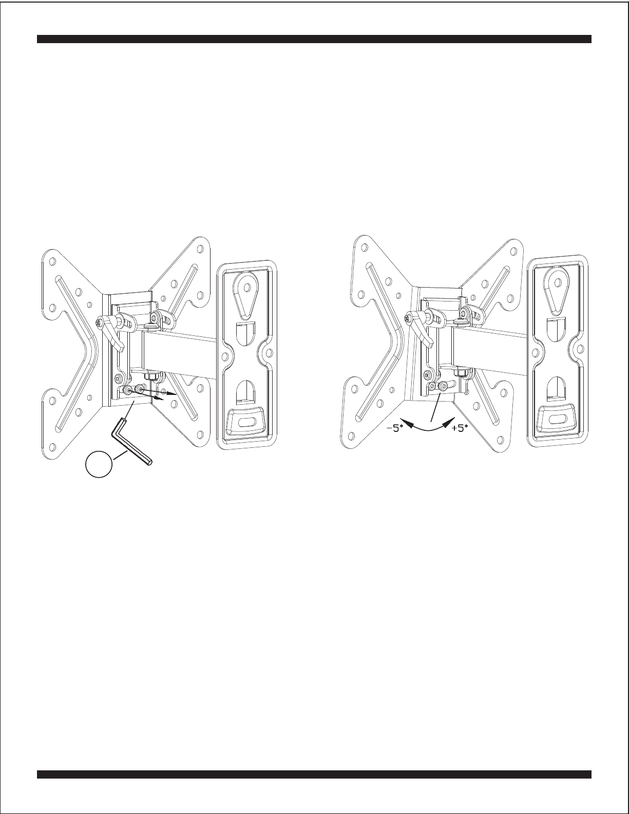
Step 6: Adjusting the Tilt
1. The Handle on the front of the Wall Plate mount arm is
used to adjust the tilt angle of the TV to your desired
angle.
2. This handle is a tension lever. To loosen the tilt
adjustment, turn the handle counterclockwise until the
handle hits the TV Plate (2) and can turn no more.
Then pull the handle away from the mount arm to release
the spring as shown in Fig. 5b, and while holding the
handle away from the mount arm, turn the handle
clockwise (Fig. 5c) and release the handle to engage
the spring. Now you can turn the handle further
counterclockwise to loosen the tilt adjustment more.
3. Adjust the tilt angle of the TV to your liking and tighten
the handle.
4. To tighten this spring loaded handle and lock in the tilt,
turn the handle clockwise and when the handle can turn
no further, pull the handle away from the mount arm and
then turn the handle counterclockwise and release.
Now you can tighten the handle further to lock in the tilt.
9
Fig. 5b
Fig. 5c
Step 7: Adjusting the Swivel
1. This wall mount can easily swivel left or right without needing to make any hardware adjustments.
2. To adjust the swivel angle, simply grab the sides of the TV with two hands and carefully slide the TV
in the desired direction. When the TV is in the desired position, carefully let go of the TV.

10
Step 8: Adjusting the Rotation
1. If necessary, the TV can be rotated from -5° to +5° by adjusting the two screws which connect the
Wall Plate (1) to the TV Plate (2) as shown in Fig. 5d.
2. To adjust the rotation, loosen these two screws with the Allen wrench (K) about 1/2 turn each, and
gently slide the TV Plate (2) to the left or right depending on your needs.
3. Once the TV Plate (2) is in the correct position, re-tighten the screws by turning the Allen wrench (K)
clockwise.
Fig. 5d
K

11
LIMITED SIX-YEAR WALL MOUNT WARRANTY
We warrant this product to you, the original purchaser at the time of purchase printed on a dated store receipt from
an authorized ETEC retailer and for a period of six-years thereafter that our wall mount product and all it’s parts
and components are free of defects in material and workmanship under normal use. This warranty is subject to
the provisions below. ETEC’s sole obligation and the purchaser’s exclusive remedy pursuant to these warranties
are limited to replacement at ETEC’s sole discretion. There are no other warranties except as expressively set
forth below either expressed or implied, including any warranty of merchantability for any particular purpose.
Should you be missing any of the assembly parts or components (screws, pieces, etc.), please contact the
Customer Support Center to secure a replacement. It is not necessary to bring the unit back to the store. When
calling, please reference the parts list found in the Instruction Manual to help us accurately identify the missing
parts and promptly provide replacements.
Our Customer Support Center is available Monday to Saturday (10:00AM to 7:00PM EST) for technical assistance
or troubleshooting. To contact us please call 1-855-994-3832.
This warranty is expressly limited to the replacement of wall mount parts and components described in the parts
list located in the Instruction Manual included with the product.
This warranty applies under conditions of normal use.
This warranty does not cover: any product, which has been subject to damage due to improper assembly or
disassembly, products which were not assembled, installed, used, or maintained in accordance with the product
assembly instructions & warnings, acts of nature, misuse, neglect, accidents, abuse, exposure to elements,
outdoor use, extreme temperature ranges, damage during transit, commercial use, modification of, or to any part
of the product or attachments to the product not approved by ETEC. Also not covered are costs for
assembly/dis-assembly labor, costs incurred in shipping the unit or parts for warranty repair/exchange or any
products purchased from unauthorized ETEC sellers. Under no circumstances shall ETEC, be liable for any loss
(direct, indirect, incidental, foreseen, unforeseen, special or consequential) or for any damage arising out of, or in
connection with, the use of this product. Nor shall ETEC have any responsibility for incidental or consequential
damages resulting from the breach of this warranty including but not limited to inconvenience, purchase or rental
of replacement products, loss of profits or commercial loss.
We reserve the right to request damaged parts or units be shipped to our offices for inspection or confirmation of
any warranty claims.
This warranty does not cover product sold ‘As Is’.
This warranty is valid only to the original purchaser of the Product in the United States and Canada and grants
specific legal rights.

Schoenfeld International Inc. and ETEC
Schoenfeld International Inc. 2013
PN: EX350SS Rev. 1.0 Sept. 2013
Table of contents
Popular TV Mount manuals by other brands

MINN KOTA
MINN KOTA MKA-23 installation instructions

Mustang
Mustang MPCD-S22V instruction manual

Vivo
Vivo MOUNT-E-DN55 instruction manual

peerless-AV
peerless-AV Tru Vue TRP740 installation instructions

STC
STC SPACE SAVER 30504 installation manual

Mounting Dream
Mounting Dream MD2210 Installation instruction