ETEKCITY MSR-A600 User manual

2
Thank You!
Thank you for purchasing the MSR-A600 Digital Multimeter
by Etekcity. We are dedicated to providing our customers with
quality products for building on better living. Should you have
any questions or concerns about using your new product, feel
free to reach out to our helpful Customer Support team at
[email protected]. We hope you enjoy your new product!

3
1 x MSR-A600 Digital Multimeter
2 x Test Leads
2 x 1.5V AAA Batteries (Pre-installed)
1 x User Manual
Package Contents
Safety Information
• International Electrical
Symbols
Function Diagram
Rotary Switch
Button Functions
LCD Screen Symbols
Before First Use
Operation
• Voltage Measurement
• Resistance Testing
• Continuity Testing
• Diode Testing
• Capacitance Testing
• DC and AC Current
Measurement
Maintenance
• Replacing the Batteries
• Checking the Fuses
• Replacing the Fuses
Specications
• General Specications
• Accuracy Specications
Warranty Information
Customer Support
3
4
5
6
7
7
8
9
10
10
11
12
12
13
14
16
16
17
18
19
19
20
24
25
Package ContentsTable of Contents

4
WARNING
Safety Information
This multimeter complies with the standards
IEC61010: in pollution degree 2, overvoltage
category (CAT. II 600V), and double insulation.
Use the multimeter only as instructed in
this operating manual, or the device may be
damaged, and you may be seriously injured.
In this manual:
WARNING : Identies conditions and
actions that are hazardous to the user or may
damage the multimeter and test leads while
operating.
NOTE: Identies the information that the user
should pay attention to.
• Please read and follow all of the
instructions and warnings in this
manual before using the product.
Failure to comply with the instructions
may result in serious injury, re,
and/or electrical shock. The person
responsible for this equipment must
ensure that all users understand and
follow the instructions.
• TO AVOID THE RISK OF ELECTRIC
SHOCK OR DAMAGE TO THE
MULTIMETER OR OTHER EQUIPMENT,
DO NOT CONNECT LEADS TO POWER
SOURCES THAT MAY EXCEED 600V.
• Expired or damaged batteries can
cause burns upon contact with skin.
ALWAYS wear proper hand protection
when handling expired or damaged
batteries.
• DO NOT alter the internal circuitry of
the multimeter. Doing so may damage
the device and will void your warranty.

5
• DO NOT use the multimeter if it is damaged
or if any part of the case is removed. Always
inspect all parts of the multimeter, the case,
and the test leads before each use.
• DO NOT use or store the multimeter in wet
or humid environments, in high-temperature
areas, around explosive or ammable
substances, or in areas with strong magnetic
elds.
• DO NOT allow children to use or play with
this device.
• DO NOT measure voltages when the
multimeter is set to measure resistance (Ω)
or current (A).
• Take special care to avoid electric shock
when the multimeter is working at an
effective voltage over 60V DC or 30V rms
AC.
• DO NOT change the settings on the rotary
switch while the test leads are connected to
a power source.
• DO NOT operate the multimeter with the
battery cover removed or without the case.
• DO NOT remove the case or open the
battery cover while the multimeter is
connected to a power source.
International Electrical Symbols
AC or DC
Double Insulated
Warning
Grounding
Low Battery
Conforms to European Union
Standards

6
Function Diagram
1. LCD Screen
2. Selection/Relative Mode Button
3. Hold/Backlight Button
4. Rotary Switch
5. 10A Terminal
6. COM Terminal
7. Terminal
1
2
5
4
6
3
7

7
Rotary Switch Button Functions
The table below briey describes each of the
rotary positions (see the Operation section for
further details, pages 10–15).
Multimeter is Off
AC Voltage Measurement
DC Voltage Measurement
AC & DC Voltage Measurement
Resistance Measurement
Continuity Test
Diode Test
Capacitance Test
DC and AC Current Measurement
(microAmps)
DC and AC Current Measurement
(milliAmps)
≤ 10A DC and AC Current
Measurement
SEL/REL
/ Current Measurement:
Press once to switch to the
alternate function.
Capacitance Test :
Press once to switch to the
Relative Mode, which removes
the capacitance of the test
leads when measuring low
capacitance values.
HOLD/
BACKLIGHT
Data Hold: Press once to hold
the displayed measurement on
the LCD screen.
Backlight On/Off: Press and
hold for 2 seconds to turn the
screen backlight on or off.
NOTE:
• The backlight will
automatically turn off after
30 seconds.
• Use the backlight while
operating the multimeter in
poorly lit areas to prevent
faulty readings.

8
LCD Screen Symbols
Symbol Description
Auto range mode. The multimeter
will automatically select the
range with the best resolution.
Auto power-off
Data hold is active
Indicates a negative reading
AC measurement indicator
DC measurement indicator
Low battery indicator
Input value is too large for the
selected range
Diode test
Continuity test
Ohm: the unit of resistance
Kilohm: 1 x 10^3 or 1,000 ohms
Symbol Description
Megaohm: 1 x 10^6 or 1,000,000
ohms.
Volts: the unit of voltage
Millivolt: 1 x 10^-3 or 0.001 volts
Amperes (amps): the unit of
current
Milliamp: 1 x 10^-3 or 0.001
amperes
Microamp: 1x 10^-6 or 0.000001
amperes
Millifarad: the unit of capacitance
Microfarad: 1 x 10^-6 or 0.000001
farads
Nanofarad: 1 x 10^-9 or
0.000000001 farads

9
Before First Use
• When setting up the multimeter, connect
the black test lead before connecting the
red test lead. To disconnect, take out the
red test lead before removing the black
test lead.
• Inspect the test leads for damaged insulation
or exposed metal parts. Check the leads for
continuity (see page 12). Replace damaged
test leads if necessary.
• Keep your ngers behind the nger guards
at all times when handling the test probes.
• ALWAYS remove the test leads from the
item being measured before changing the
settings.
• Check the fuses in the multimeter before
measuring current. Always make sure power
to the circuit has been shut off before
connecting the multimeter to the circuit.
Once you have properly connected the
multimeter, power on the circuit.
• Remember to replace the batteries as soon
as the low battery indicator “ “ appears
(see Replacing the Batteries, page 16). The
multimeter may produce incorrect readings
if it is operated with a low battery, which can
result in electric shock or injury.
• Whenever you nish measuring an object
with the multimeter, disconnect the test
leads from the object.

10
ii. AC or DC Measurement
1. Insert the black test lead into the COM
terminal, and the red test lead into the
terminal.
2. Turn the rotary dial to .
Note: The default function is DC. Press
SEL/REL to switch between AC and DC
measurement.
3. Connect the test leads to the object
being measured. Hold them in place until
the readings on the display stabilize.
4. When the measurement is complete,
disconnect the test leads from the
object, then remove the test leads from
the multimeter.
Note: In each range, the multimeter has
an input impedance of 10
MΩ
. This loading
effect can cause measurement errors
in high impedance circuits. If the circuit
impedance is less than or equal to 10
MΩ
,
the error is negligible (0.1% or less).
Voltage Measurement
Operation
WARNING
DO NOT measure voltages higher than
600V. Doing so may result in electric
shock, damage to the multimeter, or
injury to the user. Always take extra
care to avoid electric shock when
measuring high voltages.
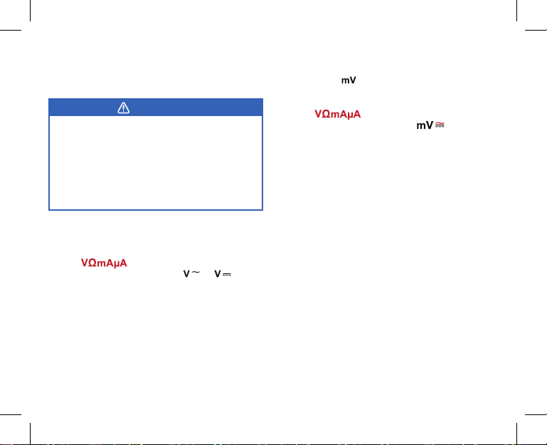
i. AC or DC Voltage
1. Insert the black test lead into the COM
terminal, and the red test lead into the
terminal.
2. Turn the rotary dial to or .
3. Connect the test leads to the object
being measured. Hold them in place until
the readings on the display stabilize.
4. When the measurement is complete,
disconnect the test leads from the
object, then remove the test leads from
the multimeter.

11
Resistance Testing
WARNING
To avoid damaging the multimeter or
the object being measured, ALWAYS
disconnect the circuit power and
discharge all high-voltage capacitors
before measuring resistance.
1. Insert the black lead into the COM
terminal, and the red test lead in to the
terminal. [Figure 1.1]
2. Turn the rotary dial to .
3. Connect the test leads to the object being
measured. Hold them in place until the
readings on the display stabilize.
Note:
• The LCD will read “ “ if there is an
open-circuit for the tested resistor or
if the resistor value is higher than the
maximum range of the multimeter.
• When testing high-resistance objects, it is
normal to wait for several seconds before
receiving a stable reading (>1MΩ). To
obtain a stable reading, use the test leads
for the shortest time possible.
• If the resistance reading with the
connected test leads is not
≤
0.5Ω, check
if the leads are loose or damaged.
• The maximum resistance rating for the
multimeter is 200MΩ.
Figure 1.1

12
Continuity Testing
WARNING
To avoid damaging the multimeter or
the object being measured, ALWAYS
disconnect the circuit power and
discharge all high-voltage capacitors
before testing for continuity.
1. Insert the black test lead into the COM
terminal, and the red test lead in to the
terminal.
2. Turn the rotary dial to .
3. Test the test leads before measurement
by connecting the metal ends of the leads
together. The multimeter will beep to
indicate that the test leads are working
properly. [Figure 2.1]
4. Connect the test leads to the object being
measured. Hold them in place until the
multimeter beeps.
Diode Testing
WARNING
To avoid damaging the multimeter or
the object being measured, ALWAYS
disconnect the circuit power and
discharge all high-voltage capacitors
before testing diodes.
This test sends a current of 2.1V through
a diode or a semiconductor junction, then
measures the voltage drop across the junction.
1. Insert the black test lead into the COM
terminal, and the red test lead in to the
terminal.
2. Turn the rotary dial to .
3. Connect the test leads to the object being
measured. Hold the leads in place until the
readings on the display stabilize.
Note:
• The LCD will read “ ” if the test leads
are incorrectly connected or if the diode
is open.
• The average value for a PN silicon
junction is 500~800mV (0.5~0.8V).
Figure 2.1

13
Capacitance Testing
WARNING
A capacitor stores an electrical charge
and may still be energized after being
removed. ALWAYS turn off all power
to the circuit before removing the
capacitor. Make sure to wear proper
protective equipment.
This test sends a current of 2.1V through
a diode or a semiconductor junction, then
measures the voltage drop across the junction.
1. Insert the black test lead into the COM
terminal, and the red test lead in to the
terminal.
2. Turn off all power to the circuit, then
remove the capacitor from the circuit.
3. Safely discharge the capacitor by touching
both ends of the capacitor to a resistor or
a piece of metal. [Figure 3.1]
4. Set the rotary switch to to test the
capacitor to ensure it is completely
discharged (see Voltage Measurement,
page 10).
5. Turn the rotary dial to .
6. Connect the test leads to the capacitor.
The negative end is often marked on the
side of the capacitor. Hold the test leads
until the reading on the display stabilizes.
Figure 3.1
Note:
• When measuring low capacitance values,
the Relative Mode can be used to remove
the capacitance of the test leads. Press
SEL/REL while on the capacitance
testing range to switch to the Relative
Mode.
• It will take longer for the reading on the
LCD to stabilize when testing a large-
capacity capacitor.
• The LCD will read “ ” to indicate
whether the capacitor has shorted out or
if it has exceeded the maximum range.

14
DC and AC Current Measurement
WARNING
• Before measuring current, ALWAYS
make sure the power supply for the
circuit has been switched off. Check
if the leads are connected to the
correct input terminals and that the
rotary switch has been turned to the
correct measurement range.
• ALWAYS connect the test leads in
series. DO NOT connect the test
leads in parallel with any circuit while
taking measurements. Doing so may
result in damage to the multimeter or
injury to the user. [Figure 4.1]
• If the current being tested is greater
than 10A, measure the current for
less than 10 seconds, then wait at
least 15 minutes before taking the
next measurement.
Figure 4.1
Series
Parallel

15
4. (Optional) To switch to AC current
measurement, press SEL/REL once.
5. Carefully break the current path to be
tested.
6. Connect the red test lead to the positive
side of the break, and the black test lead
to the negative side of the break.
7. Turn on the circuit power. The measured
value will show on the LCD.
1. Turn off power to the circuit and discharge
all high-voltage capacitors.
2. Insert the black test lead into the COM
terminal. If you are measuring microamps
(μA) or milliamps (mA), insert the red test
lead into the terminal. If you are
measuring Amps (A), insert the red test
lead into the 10A terminal.
3. Set the rotary dial to the correct current
measurement range.
Note: If you are unsure of the range of
the current you are measuring, select the
highest range (A) rst (inserting the red
test lead into the 10A terminal), then
use the lower ranges to nd an accurate
measurement.
Note: If the display only reads “ 0.0 ” when
measuring current using the
Terminal, it means that the 200mA fuse
must be replaced.

16
WARNING
To avoid false readings, replace the
batteries as soon as “ “ appears on
the LCD screen.
• Regularly use a dry cloth to dust the
protective case and multimeter interface.
• DO NOT use cleaning detergents or abrasive
cleaners on the protective case or on the
multimeter.
• If you are experiencing any issues with the
multimeter, contact our Customer Support
Team (page 25).
1. Disconnect the test leads from the input
terminals on the multimeter.
2. Turn off the multimeter by turning the
rotary dial to .
3. Carefully remove the multimeter from its
protective case.
General Maintenance
Replacing the Batteries
Maintenance
4. Using a small screwdriver, remove the
screw securing the battery compartment
cover on the back of the multimeter.
[
Figure 5.1 on next page
]
5. Remove the old batteries and properly
dispose of them.
6. Install new 1.5V AAA batteries into the
compartment under the correct polarity.
7. Replace and secure the battery
compartment.
Note:
• ONLY use 1.5V AAA batteries when
replacing the batteries in the multimeter.
Be sure to install the batteries in the
multimeter under the correct polarity.
• DO NOT dispose of old batteries
in normal trash or in res. Always
follow your local environmental waste
regulations.
• If the multimeter is not going to be used
for an extended period of time, remove
the batteries before storage.

17
Properly dispose of
the old batteries.
1.5V AAA battery
Figure 5.1
Checking the Fuses
10A Fuse
Always check the 10A fuse before each use,
especially before measuring current. If the
internal fuse is overloaded, you must
immediately replace it.
1. Plug the red test lead into the
terminal.
2. Turn the rotary dial to .
3. Insert the metal end of the red test lead
into the 10A terminal. If the multimeter
beeps, then the internal fuses are still
ready. If the multimeter does not beep,
then the internal fuses have been
overloaded and the LCD will read “ ”.
200mA Fuse
If the display only reads “ 0.0 ” when
measuring current using the
Terminal, it means that the 200mA fuse must
be replaced.
Note:
•
10A
Terminal Fuse: 10A/600V
Φ5x20mm
• Terminal Fuse: 200mA/600V
Φ5x20mm

18
Replacing the Fuses
1. Disconnect the test leads from the
multimeter and turn the rotary switch to
.
2. Carefully remove the rubber case from the
multimeter.
3. Use a small screwdriver to remove the
screws at the bottom of the multimeter.
Once the screws are removed, carefully
separate the front and rear panels.
4. Replace the fuse(s) that need to be
changed. [
Figure 6.1
]
WARNING
To avoid electrical shock, arc blasts, arc
ashes, personal injury, or damage to
the multimeter, use the specied fuses
ONLY in accordance with the following
procedure.
Figures 6.1
5. Reconnect the front and back panels, then
replace the screws to secure the panels
together. Place the protective case back
onto the multimeter.
Note: Make sure the fuses are placed in the
correct ports.

19
General Specications
Maximum Voltage 600V
Maximum Overload Protection 600V rms (AC or DC)
Measurement Speed 2~3 times/second
Fused Protection VΩmAµA Terminal: 200mA
10A Terminal: 10A
Temperature Operating: 32° – ±104°F (0°C – ±40°C)
Storage: 14° – ±122°F (-10° – ±50°C)
Relative Humidity ≤ 75% @ 0°~30°C
≤ 50% @ 30–40°C
Maximum Display Value 1999
Overload Display OL
Battery Type 2 x 1.5V AAA Batteries
(Pre-installed)
Dimensions 5.5 x 3 x 1.9 in. (140 x 77 x 48 mm)
Weight 7.1 oz (204 g)
Specications

20
Accuracy Specications
Range Resolution Accuracy
200.0mV 0.1mV ±(0.7%+3)
2000mV 1mV ± (0.5%+2)
20.00mV 0.01V
±(0.7%+3)200.0V 0.1V
600V 1V
Note:
• The following specications are based on
testing the multimeter in an environmental
temperature range of 64.4°–82.4°F
(18°–28°C). If the temperature is out of
this range, it is required to multiply the
measurement by a temperature coefcient.
• Temperature coefcient:
0.1 x (specied accuracy)/°C (<18°C or >28°C)
• Input impedance is about 10MΩ.
• There may be unstable readings when
using the mV range while the leads are not
connected. This is a normal. The reading will
become stable once the leads are connected.
• The max input voltage: ±600V. When the
voltage is more than 610V, the LCD will read
“ ”.
i. DC Voltage
Table of contents
Other ETEKCITY Multimeter manuals