ETEKCITY MSR-R500 User manual

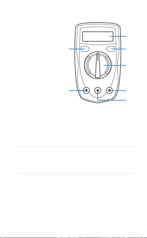
Thank you for purchasing the Etekcity® MSR-R500
Digital Multimeter. Measure DC and AC voltage, current,
diode and audible continuity, and resistance with the
convenience of one single tool with built-in overload
protection.
Safe and Proper Usage
WARNING: TO AVOID THE RISK OF ELECTRIC
SHOCK OR THE DAMAGE OF THE MULTIMETER OR
OTHER EQUIPMENT, DO NOT CONNECT TO ANY
INPUT TERMINALS OF THE MULTIMETER THAT
MAY EXCEED 500V.
Read all the instructions provided in this manual.
Failure to comply with the instructions in the manual
and/or use of the device in ways other than the ones
mentioned in the manual may result in serious injury,
fire, and/or electrical shock. The person responsible for
this equipment must ensure that all users understand
the directions and adhere to them.
This meter complies with standard IEC61010: in
pollution degree 2, overvoltage category (CAT I 600V,
CAT II 300V) and double insulation.
CAT I: Signal level, special equipment or parts of
equipment, telecommunications, electronic, etc.
CAT II: Local level, appliance, PORTABLE EQUIPMENT
etc., with smaller transient overvoltages than CAT III.
Safety Operating Procedures
• Be sure to read, understand and comply with all the
instructions in this manual.
• Make sure the test leads are in a safe state. Keep
- 1 -

equipment out of humidity or moist environments.
• DO NOT use the meter if it is damaged or the case (or
part of the case) is removed. Look for cracks or
missing plastic. Check the insulation around the
connectors before use.
• DO NOT use the equipment in wet environments.
• Remove the test probes from the item of
measurement before changing the settings or
measurement functions on the multimeter.
• DO NOT apply the multimeter to voltages that may
exceed 500V.
• DO NOT measure voltages when the meter is set to
measure resistance (Ω).
• Always use the fuses of the correct type as specified
within the instructions to avoid any injury, electrical
shock, or risk of fire.
• DO NOT operate the meter around explosive gas,
vapor, or dust.
• When operating the test probes, keep your fingers
behind the finger guards.
• When making electrical connections, connect the
common test lead (black) before connecting the live
test lead (red). When disconnecting, disconnect the
live test lead (red) before disconnecting the common
test lead (black).
• Always remove the test leads before replacing the
battery within the multimeter or opening the battery
compartment.
• Inspect the condition of the test leads and the
multimeter for any damage before operating the
meter. Repair or replace any damage before use.
• Verify the meter’s operation by measuring a known
voltage before and after using the meter.
• DO NOT change the settings on the rotary switch
while the test leads are measuring a source of power.
• Use great care when making measurements if the
- 2 -

voltages are greater than 25VAC rms or 35VDC.
These voltages are considered to be a shock hazard.
• DO NOT operate the meter with the battery cover
removed or the case open.
• DO NOT remove the cover or open the case of the
meter without first removing it from the main power
source.
• DO NOT allow children to operate this device.
• USE a 9V DC battery when replacing the battery
within the device.
• Make sure to insert the battery under the correct
polarity indicated in the device.
• DO NOT use leaking batteries.
• DO NOT dispose old batteries in fire.
• Expired or damaged batteries can cause cauterization
on contact with skin. Always therefore, use suitable
hand gloves for protection in such cases.
• Disconnect circuit power and discharge all high
voltage capacitors before testing resistance,
continuity, diodes, or capacitance.
• Before measuring current, check the meter’s fuses
and turn off power to the circuit before connecting
the meter to the circuit.
• In the case the device is going to be unused for an
extended period of time, remove the battery before
storage.
AC or DC Low Battery
AC Current Diode
DC Current Fuse
Earth Ground Continuity Test
Double Insulated Warning
- 3 -

1
3
4
5
7
2
6
Meter Diagram
1. LCD Display
2. HOLD Button
3. Backlight Button
4. Rotary Switch
5. COM Terminal
6. 10A Terminal
7. Other Terminals
Figure 1
Button Functions
Button Operation
HOLD
BACKLIGHT
• Press once to lock measurement
results (An ‘H’ symbol will appear on
the display)
• Press once more to unlock results
• Press once to turn on the display
backlight
• Press once more to turn off backlight
- 4 -

General Specifications
Maximum Voltage
(Including transient
overvoltage)
Between any
Terminals &
Grounding
500V rms
Fused Protection for
VΩmA
Input Terminal
500mA, 250V fast type,
φ5x20mm
10A Terminal 10A, 250V fast type,
φ5x20mm
Range Manual Ranging
Maximum Display 1999
Measurement Speed Updates 2 ~ 3 times/second
Temperature Operating: 0°C ~ 40°C (32°F ~
104°F)
Storage: -10°C ~ 50°C (14°F ~
122°F)
Relative Humidity 75% at 0°C ~ 30°C
< 50% at 31°C ~ 40°C
Altitude Operating: <2,000m
Storage: <10,000m
Accuracy (a% reading + b digits)
Guaranteed for 1 year
- 5 -

Range Resolution Accuracy
200mV 100µV
± (0.5%+2)
2000mV 1mV
Overload
Protection
250V DC
or AC
500V DC
or AC
20V 10mV
200V 100mV
500V 1V ± (0.8%+2)
Input impendance: 10MΩ
AC Voltage
Range Resolution Accuracy Overload
Protection
200V 100mV ± (1.2%+10) 500V DC
or AC
500V 1V
• Input impendance: approx. 5MΩ
• Displays effective value of sine wave (mean value
response)
• Frequency response 40Hz ~ 400Hz
Battery Type: 1 x 9V Battery NEDA 1604 / 6F22 / 006P
Overload Display: 1
Dimensions: 130 x 73.5 x 35mm
Weight: ~156g
DC Voltage
- 6 -

DC Current
Range Resolution Accuracy Overload
Protection
500mA,
250V fast
type fuse:
5x20mm
10A/250V
fast type
φ
5x20mm
2000µA 1µA
± (1%+2)
20mA 10µA
200mA 100µA± (1.2%+2)
10A 10mA ± (2%+5)
At 10A Range: for continuous measurement ≤10 seconds
and interval not less than 15 minutes
Resistance
Range Resolution Accuracy
200Ω0.1Ω± (0.8%+5)
Overload
Protection
250V DC
or AC
2000Ω1Ω
± (0.8%+2)20KΩ10Ω
200KΩ100Ω
20MΩ10KΩ± (1%+5)
200MΩ100KΩ± [5%(reading-10)+10]
- 7 -

Diodes and Continuity Measurement
Range Resolution Remark Overload
Protection
1mV
Display
approximate
forward voltage
drop: 0.5v ~ 0.8v 250V DC or AC
1ΩBuzzer beeps
at < 70Ω
Square Wave Output
Range Illustration
OUT
Approx. output 50Hz square wave signal.
As a simple signal source with 47KΩ
resistance output.
No overload protection
Make sure voltage output of calibrated equipment level is
less than 10V to avoid damages to the meter
- 8 -

Figure 2
Measurement Operation
DC Voltage Measurement
DC Voltage Ranges: 200mV, 2000mV, 20V, 200V, 500V
Input Impedance: 10MΩ
1. Plug the red test lead into the VΩmA terminal, then
plug the black test lead into the COM terminal.
2. Set the rotary switch to the appropriate
measurement in V range.
3. Connect the test leads to the object of measurement.
Hold them in place until the results on the display
stabilize.
4. When measurement is completed, disconnect the test
leads from the object of measurement.
NOTE
• If the value of voltage is unknown, use the maximum
measurement position (500V) and reduce the range
until proper readings are obtained.
• The LCD will display “OL” if there in an overload
within the selected range. Select a higher range to
obtain a correct reading.
• If the circuit impedance is less than or equal to 10kΩ,
the error is negligible (0.1% or less).
- 9 -

AC Voltage Measurement
(See Figure 2)
AC Voltage Ranges: 200V, 500V
Input Impedance: 5MΩ
1. Plug the red test lead into the VΩmA terminal, then
plug the black test lead into the COM terminal.
2. Set the rotary switch to the appropriate
measurement in V~ range.
3. Connect the test leads to the object of measurement.
Hold them in place until the results on the display
stabilize. The displayed measured value is the value
of sine wave (mean value response).
4. When measurement is completed, disconnect the test
leads from the object of measurement.
NOTE
• If the value of voltage is unknown, use the maximum
measurement position (500V) and reduce the range
until proper readings are obtained.
• The LCD will display “OL” if there in an overload
within the selected range. Select a higher range to
obtain a correct reading.
• If the circuit impedance is less than or equal to 10kΩ,
the error is negligible (0.1% or less).
- 10 -

DC Current Measurement
WARNING
Never attempt an in-circuit current measurement
where the voltage between the terminals and ground is
greater than 60V. If the fuse burns out during
measurement, this may cause harm to the user and/or
damage to the device. Use proper terminals, functions,
and range for measurement.
When the testing leads are connected to the current
terminals, do not parallel them across any circuit.
Figure 3
DC Current Ranges: 2000μA, 20mA, 200mA, 10A
1. Turn off the power to the circuit and discharge all
highvoltage capacitors.
2. Plug the red test lead into the VΩmA or 10A terminal,
then plug the black test lead into the COM terminal.
3. Set the rotary switch to the appropriate
measurement in A range.
4. Break the current path to be tested.
5. Connect the red test lead to the most positive side of
the break and the black test lead to the most
negative side of the break.
6. Turn on the circuit power.
- 11 -

7. When measurement is completed, disconnect the
test leads from the object of measurement.
NOTE
If the value of voltage is unknown, use the maximum
measurement position (10A) and reduce the range until
proper readings are obtained.
Figure 4
Resistance Measurement
Resistance Ranges: 200Ω, 2000Ω, 20kΩ, 200kΩ, 20MΩ,
200MΩ
1. Plug the red test lead into the VΩmA terminal, then
plug the black test lead into the COM terminal.
2. Set the rotary switch to the appropriate
measurement in Ω range.
3. Connect the test leads to the object of measurement,
the measured value will appear on the display.
4. When measurement is completed, disconnect the test
leads from the object of measurement.
NOTE
• The test leads can add 0.1Ωto 0.3Ωof error to the
resistance measurement. To obtain precise readings
in lowresistance measurement (200Ω), short-circuit
- 12 -

Figure 5
Diode Measurement
WARNING
the input terminals beforehand and record the
reading obtained (reading X). This is the additional
resistance from the test lead. Then use the equation:
Measured resistance value (Y) - (X) = resistance result
• For high-resistance measurements (>1MΩ), it may take
a few seconds for the reading result to stabilize.
To avoid damage to the meter and/or the object of
measurement, disconnect the circuit power and
discharge all the high-voltage capacitors before diodes.
Test to check diodes, transistors, and other
semiconductor devices. The diode test sends a current
through the semiconductor junction, then measures the
voltage drop across the junction. A good silicon junction
drops between 0.5V and 0.8V.
- 13 -

1. Plug the red test lead into the VΩmA terminal, then
plug the black test lead into the COM terminal.
2. Set the rotary switch to the setting.
3. For forward voltage drop readings on any
semiconductor component, place the red test lead on
the component’s anode and place the black test lead
on the component’s cathode. Hold them in place until
the results on the display stabilize.
4. When measurement is completed, disconnect the test
leads from the object of measurement.
NOTE
• In a circuit, a good diode should still produce a
forward voltage drop reading of 0.5V to 0.8V;
however, the reverse voltage drop reading can vary
depending on the resistance of other pathways
between the probe tips.
• The LCD will display “OL” if the open-circuit is
incorrectly connected.
• The unit of diode is volt (V), displaying the
positiveconnection voltage-drop value.
Continuity Measurement
1. Plug the red test lead into the VΩmA terminal, then
plug the black test lead into the COM terminal.
2. Set the rotary switch to the setting.
3. Connect the test leads across with the object of
measurement.
4. The buzzer will sound if the resistance of the circuit
is under 70Ω.
NOTE
The LCD will display “OL” if the circuit is open.
- 14 -

WARNING
Square Wave Output
To avoid damage to the meter and/or the object of
measurement, do not allow output terminals (red test
lead) to surpass 10V.
1. Plug the red test lead into the VΩmA terminal, then
plug the black test lead into the COM terminal.
2. Set the rotary switch to the OUT setting.
3. Connect the test leads across with the object of
measurement. Hold them in place until the results on
the display stabilize.
4. When measurement is completed, disconnect the test
leads from the object of measurement.
NOTE
• The frequency is approximately 50Hz.
• When loaded to 1MΩ, the output scope will be higher
than 3Vpp.
- 15 -

WARNING
Maintenance
• To avoid false readings, possible electrical shock
and/or personal injury, replace the battery as soon as
the low battery indicator appears on the display.
• To avoid electrical shock, arc blast, personal injury,
and/or damage to the meter, use the specified fused
ONLY in accordance with the following procedure.
Battery and Fuse Replacement
1. Disconnect the test leads from the input terminals of
the meter.
2. Turn OFF the meter
3. Using a screwdriver, unscrew the battery
compartment located on the bottom of the meter.
Slide off the battery compartment cover.
4. Remove the used batteries from the battery
compartment.
5. Remove the fuse by gently prying one end loose,
then take the fuse out from its bracket.
6. Replace the battery with a new 9V battery.
7. Install replacement fuses with the identical type and
specification: 500mA, 250V fast type,φ5x20mm
and 10A, 250V fast type,φ5 x 20mm (make sure the
fuse is fixed firmly in the bracket).
8. Re-apply the compartment cover and reinstall the
screw firmly.
- 16 -

Warranty Information
Etekcity Corporation (“Etekcity”) warrants this product to
the original purchaser to be free from defects in material
and workmanship, under normal use and conditions, for a
period of 2 years from the date of original purchase.
Etekcity agrees, at our option during the warranty period,
to repair any defect in material or workmanship or furnish
an equal product in exchange without charge, subject to
verification of the defect or malfunction and proof of the
date of purchase.
There is no other express warranty. This warranty does not
apply:
If the product has been modified from its original condition;
If the product has not been used in accordance with
directions and instructions in the user manual;
To damages or defects caused by accident, abuse, misuse
or improper or inadequate maintenance;
To damages or defects caused by service or repair of the
product performed by an unauthorized service provider or
by anyone other than Etekcity;
To damages or defects occurring during commercial use,
rental use, or any use for which the product is not intended;
To damages or defects exceeding the cost of the product.
Etekcity will not be liable for indirect, incidental, or
consequential damages in connection with the use of the
product covered by this warranty.
This warranty extends only to the original consumer
purchaser of the product and is not transferable to any
subsequent owner of the product regardless of whether the
product is transferred during the specified term of the
warranty.
This warranty does not extend to products purchased from
unauthorized sellers. Etekcity’s warranty extends only to
products purchased from authorized sellers that are subject
to Etekcity’s quality controls and have agreed to follow its
quality controls.
All implied warranties are limited to the period of this limited
warranty.
This warranty gives you specific legal rights and you may
also have other rights which vary from state to state. Some
states do not allow the exclusion or limitation of incidental or
consequential damages, so the above limitation or exclusion
may not apply to you.
If you discover that your product is defective within the
specified warranty period, please contact Customer Support
before contacting us. Once our Customer Support Team has
approved your request, please return the product with a
copy of the invoice and order ID.
Every Etekcity product automatically includes a 2-year
warranty. To make the customer support process quick and
easy, register your product online at
www.etekcity.com/warranty.
This warranty is made by:
Etekcity Corporation
1202 N. Miller St., Suite A
Anaheim, CA 92806
- 17 -

This warranty does not extend to products purchased from
unauthorized sellers. Etekcity’s warranty extends only to
products purchased from authorized sellers that are subject
to Etekcity’s quality controls and have agreed to follow its
quality controls.
All implied warranties are limited to the period of this limited
warranty.
This warranty gives you specific legal rights and you may
also have other rights which vary from state to state. Some
states do not allow the exclusion or limitation of incidental or
consequential damages, so the above limitation or exclusion
may not apply to you.
If you discover that your product is defective within the
specified warranty period, please contact Customer Support
before contacting us. Once our Customer Support Team has
approved your request, please return the product with a
copy of the invoice and order ID.
Every Etekcity product automatically includes a 2-year
warranty. To make the customer support process quick and
easy, register your product online at
www.etekcity.com/warranty.
This warranty is made by:
Etekcity Corporation
1202 N. Miller St., Suite A
Anaheim, CA 92806
- 18 -

Customer Support
If you encounter any issues or have any questions
regarding your new product, please contact our helpful
Customer Support Team. Your satisfaction is our goal!
*Please have your order confirmation number ready before
contacting Customer Support.
Etekcity Corporation
1202 N Miller St., Suite A
Anaheim, CA 92806
Toll Free: (855) 686-3835
Email: [email protected]
Support Hours
Mon - Fri,
9:00 am - 5:00 pm PST/PDT
- 19 -
A4_21J13
Other manuals for MSR-R500
1
Table of contents
Other ETEKCITY Multimeter manuals