Eterbright CIGS-3000A1 Series User guide

Installation and Safety Manual of CIGS-3000A1&E1 Solar Photovoltaic Module
This document and all information contained herein is the sole property of ETERBRIGHT SOLAR CORPORATIO and shall not be distributed, reproduced, or
disclosed in whole or in part without the prior written consent of ETERBRIGHT SOLAR CORPORATIO .
A3-224
INS ALLA ION AND SAFE Y MANUAL for
CIGS-3000A1 and CIGS-3000E1
Solar Photovoltaic Modules
Release Date: 2019.6.20
Version: 1.2
CIGS-3000A1 Series
CIGS-3000A1, CIGS-3050A1, CIGS-3100A1, CIGS-3150A1, CIGS-3200A1,
CIGS-3250A1, CIGS-3300A1, CIGS-3350A1, CIGS-3400A1, CIGS-3450A1,
CIGS-3500A1, CIGS-3550A1, CIGS-3600A1, CIGS-3650A1, CIGS-3700A1
CIGS-3750A1
CIGS-3000E1 Series
CIGS-3000E1, CIGS-3050E1, CIGS-3100E1, CIGS-3150E1, CIGS-3200E1,
CIGS-3250E1, CIGS-3300E1, CIGS-3350E1, CIGS-3400E1, CIGS-3450E1,
CIGS-3500E1, CIGS-3550E1, CIGS-3600E1, CIGS-3650E1, CIGS-3700E1,
CIGS-3750E1

Installation and Safety Manual of CIGS-3000A1&E1 Solar Photovoltaic Module
This document and all information contained herein is the sole property of ETERBRIGHT SOLAR CORPORATIO and shall not be distributed, reproduced, or
disclosed in whole or in part without the prior written consent of ETERBRIGHT SOLAR CORPORATIO .
A3-224
Contents
1. Introduction
2. Disclaimer of Liability
3. General Information
4. Warnings and Cautions
5. Safety
6. Product Characteristics
7. General Installation
8. Mechanical Installation
9. Electrical Installation
10. Maintenance
11. Shut Down Generation System
12. Revision History

Installation and Safety Manual of CIGS-3000A1&E1 Solar Photovoltaic Module
This document and all information contained herein is the sole property of ETERBRIGHT SOLAR CORPORATIO and shall not be distributed, reproduced, or
disclosed in whole or in part without the prior written consent of ETERBRIGHT SOLAR CORPORATIO .
A3-224
1. Introduction
his manual provides information regarding the installation and safe handling of the
E ERBRIGH SOLAR CORPORA ION CIGS solar photovoltaic module. ALL of the instructions
in this manual should be read carefully before attempting installation. If there are any
questions, please contact E ERBRIGH SOLAR CORPORA ION echnical Service department
for further explanation.
Please retain this manual for your future reference.
2. Disclaimer of Liability
Because the use of this manual and the conditions or methods of installation, operation,
use and maintenance of photovoltaic product are beyond E ERBRIGH SOLAR
CORPORA ION’s control, E ERBRIGH SOLAR CORPORA ION does not accept responsibility,
and expressly disclaims liability for loss, damage, or expense arising out of, or in any way
connected with, such installation, operation, use or maintenance.
No responsibility is assumed by E ERBRIGH SOLAR CORPORA ION for any infringement of
patents or other rights of third parties, which may result from the use of the PV product.
No license is granted by implication or otherwise under any patent or patent rights.
If you do not adhere to the instructions given in this manual, your rights under the
E ERBRIGH SOLAR CORPORA ION warranty may be forfeited.
E ERBRIGH SOLAR CORPORA ION reserves the right to change the manual, the PV
product, the specifications, or product information sheets without prior notice.
3. General Information
Installation should be performed only by qualified persons. Before installation, installers
should assume the risk of all injuries that might occur during installation, including, but not
limited to, the risk of electric shock. Installers must conform to all safety precautions in the
manual when installing modules.
4. Warnings and Cautions
4.1 Warnings
One individual module may generate DC voltages greater than 30 volts when exposed
to direct sunlight. Contact with a DC voltage of 30V or more is potentially hazardous.
Installers should know in advance that the risk of injury may occur during the
installation, including electric shock.
All PV modules should be installed according to all local and national applicable
standards, codes and regulations.
Rooftop installations should be placed over fire resistant roofs ONLY.

Installation and Safety Manual of CIGS-3000A1&E1 Solar Photovoltaic Module
This document and all information contained herein is the sole property of ETERBRIGHT SOLAR CORPORATIO and shall not be distributed, reproduced, or
disclosed in whole or in part without the prior written consent of ETERBRIGHT SOLAR CORPORATIO .
A3-224
Artificially concentrated sunlight shall not be directed on the module or panel
4.2 Cautions
Do not attempt to disassemble the modules, and do not remove any attached
nameplates or components from the modules.
Do not apply paint or adhesive to module top surface.
Do not use mirrors or other magnifiers to artificially concentrate sunlight on the
modules.
5. Safety
5.1 Handling Safety
Wear non-slip gloves to prevent the modules from falling while handling the modules.
Keep children/pets away in the process of handling and installing the modules.
Do not stand or step on the module.
o avoid glass breakage, do not place any heavy objects on the module.
Do not drop the module heavily.
5.2 Installation Safety
DO NO DISCONNEC UNDER LOAD.
COMPLE ELY cover the module with an opaque material during installation to prevent
electricity from being generated.
Use ONLY insulated tools and insulated gloves that meet the electrical installation
standards.
Abide by the safety regulations for all other components used in the system, including
wiring and cables, connectors, charging regulators, inverters, storage batteries and
rechargeable batteries, etc.
Do not wear metallic rings, watchbands, ear, nose, lip rings or other metallic objects
while installing or maintaining photovoltaic systems.
he parts of installation CANNO cover the drainage holes.
6. Product Characteristics
he power rating of E ERBRIGH SOLAR CORPORA ION CIGS solar photovoltaic module are
measured under standard test conditions (Irradiance 1000W/m
2
, module temperature of
25℃(77℉), AM 1.5G ), so that the power output of module will vary under actual
operating conditions.
he amount of DC power generated by the solar photovoltaic module is proportional to the
radiation intensity, but the voltage will vary depending on the temperature.

Installation and Safety Manual of CIGS-3000A1&E1 Solar Photovoltaic Module
This document and all information contained herein is the sole property of ETERBRIGHT SOLAR CORPORATIO and shall not be distributed, reproduced, or
disclosed in whole or in part without the prior written consent of ETERBRIGHT SOLAR CORPORATIO .
A3-224
6.1Electrical Characteristics
A. At Standard Test Conditions(STC)
*1
Module models
CIGS-3000A1
CIGS-3050A1
CIGS-3100A1
CIGS-3150A1
CIGS-3200A1
Minimum power (P
MPP
) [W]
300 305 310 315 320
Power tolerance [%]
+5/-3 +5/-3 +5/-3 +5/-3 +5/-3
Open circuit voltage (V
OC
) [V]
72.3 72.5 72.7 72.8 73.0
Short circuit current (
SC
) [A]
6.56 6.58 6.60 6.62 6.64
Voltage at P
MPP
[V]
54.4 54.8 55.1 55.4 55.7
Current at P
MPP
[A]
5.51 5.57 5.63 5.69 5.75
Module models
CIGS-3250A1
CIGS-3300A1
CIGS-3350A1
CIGS-3400A1
CIGS-3450A1
Minimum power (P
MPP
) [W]
325 330 335 340 345
Power tolerance [%]
+5/-3 +5/-3 +5/-3 +5/-3 +5/-3
Open circuit voltage (V
OC
) [V]
73.1 73.3 73.5 73.6 73.8
Short circuit current (
SC
) [A]
6.67 6.69 6.71 6.73 6.75
Voltage at P
MPP
[V]
55.9 56.2 56.5 56.9 57.1
Current at P
MPP
[A]
5.81 5.87 5.93 5.98 6.04
Module models
CIGS-3500A1
CIGS-3550A1
CIGS-3600A1
CIGS-3650A1
CIGS-3700A1
Minimum power (P
MPP
) [W]
350 355 360 365 370
Power tolerance [%]
+5/-3 +5/-3 +5/-3 +5/-3 +5/-3
Open circuit voltage (V
OC
) [V]
73.9 74.0 74.1 74.3 74.5
Short circuit current (
SC
) [A]
6.95 6.96 6.96 6.96 6.96
Voltage at P
MPP
[V]
55.6 56.3 57.0 57.5 58.1
Current at P
MPP
[A]
6.30 6.31 6.32 6.35 6.37
Module models
CIGS-3750A1
Minimum power (P
MPP
) [W]
375
Power tolerance [%]
+5/-3
Open circuit voltage (V
OC
) [V]
74.8
Short circuit current (
SC
) [A]
6.98
Voltage at P
MPP
[V]
58.7
Current at P
MPP
[A]
6.39

Installation and Safety Manual of CIGS-3000A1&E1 Solar Photovoltaic Module
This document and all information contained herein is the sole property of ETERBRIGHT SOLAR CORPORATIO and shall not be distributed, reproduced, or
disclosed in whole or in part without the prior written consent of ETERBRIGHT SOLAR CORPORATIO .
A3-224
Module models
CIGS-3000E1
CIGS-3050E1
CIGS-3100E1
CIGS-3150E1
CIGS-3200E1
Minimum power (P
MPP
) [W]
300 305 310 315 320
Power tolerance [%]
+5/-3 +5/-3 +5/-3 +5/-3 +5/-3
Open circuit voltage (V
OC
) [V]
72.3 72.5 72.7 72.8 73.0
Short circuit current (
SC
) [A]
6.56 6.58 6.60 6.62 6.64
Voltage at P
MPP
[V]
54.4 54.8 55.1 55.4 55.7
Current at P
MPP
[A]
5.51 5.57 5.63 5.69 5.75
Module models
CIGS-3250E1
CIGS-3300E1
CIGS-3350E1
CIGS-3400E1
CIGS-3450E1
Minimum power (P
MPP
) [W]
325 330 335 340 345
Power tolerance [%]
+5/-3 +5/-3 +5/-3 +5/-3 +5/-3
Open circuit voltage (V
OC
) [V]
73.1 73.3 73.5 73.6 73.8
Short circuit current (
SC
) [A]
6.67 6.69 6.71 6.73 6.75
Voltage at P
MPP
[V]
55.9 56.2 56.5 56.9 57.1
Current at P
MPP
[A]
5.81 5.87 5.93 5.98 6.04
Module models
CIGS-3500E1
CIGS-3550E1
CIGS-3600E1
CIGS-3650E1
CIGS-3700E1
Minimum power (P
MPP
) [W]
350 355 360 365 370
Power tolerance [%]
+5/-3 +5/-3 +5/-3 +5/-3 +5/-3
Open circuit voltage (V
OC
) [V]
73.9 74.0 74.1 74.3 74.5
Short circuit current (
SC
) [A]
6.95 6.96 6.96 6.96 6.96
Voltage at P
MPP
[V]
55.6 56.3 57.0 57.5 58.1
Current at P
MPP
[A]
6.30 6.31 6.32 6.35 6.37
Module models
CIGS-3750E1
Minimum power (P
MPP
) [W]
375
Power tolerance [%]
+5/-3
Open circuit voltage (V
OC
) [V]
74.8
Short circuit current (
SC
) [A]
6.98
Voltage at P
MPP
[V]
58.7
Current at P
MPP
[A]
6.39
Remark*1 STC: Irradiance 1000 /m
2
, Module Temperature 25
, Air Mass1.5
he electrical characteristics are within ±10% of the indicated values of Isc and Voc
under S C. Pmax olerance (UL) before UL 1703 Light Soaking olerance is +3/-3%; after
Light Soaking (UL 1703) olerance is +5/-3%.
Under normal conditions, the current and voltage generated by the solar photovoltaic

Installation and Safety Manual of CIGS-3000A1&E1 Solar Photovoltaic Module
This document and all information contained herein is the sole property of ETERBRIGHT SOLAR CORPORATIO and shall not be distributed, reproduced, or
disclosed in whole or in part without the prior written consent of ETERBRIGHT SOLAR CORPORATIO .
A3-224
module are different from those listed in the specification. he value of Isc (short
circuit current) and Voc (open circuit voltage) listed in the specification are measured at
standard test conditions; therefore, the value of Isc and Voc marked on this module
should be multiplied by a factor of 1.25 when determining component voltage ratings,
conductor current ratings, fuse sizes, and size of controls connected to the module
output. An additional 1.25 multiplier for a total of 1.5625 may be required by certain
codes for sizing fuses and conductors.
B.
Nominal Module Operating Temperature (NMOT)
Module models
CIGS-3000A1
CIGS-3050A1
CIGS-3100A1
CIGS-3150A1
CIGS-3200A1
Minimum power (P
MPP
) [W]
220.8 224.6 228.4 232.2 236.0
Open circuit voltage (V
OC
) [V]
67.9 68.1 68.3 68.4 68.6
Short circuit current (
SC
) [A]
5.25 5.26 5.28 5.30 5.31
Voltage at P
MPP
[V]
50.1 50.4 50.7 51.0 51.3
Current at P
MPP
[A]
4.41 4.46 4.50 4.55 4.60
Module models
CIGS-3250A1
CIGS-3300A1
CIGS-3350A1
CIGS-3400A1
CIGS-3450A1
Minimum power (P
MPP
) [W]
239.7 243.5 247.3 251.2 254.9
Open circuit voltage (V
OC
) [V]
68.7 68.9 69.1 69.2 69.4
Short circuit current (
SC
) [A]
5.34 5.35 5.37 5.38 5.40
Voltage at P
MPP
[V]
51.6 51.9 52.1 52.5 52.8
Current at P
MPP
[A]
4.65 4.70 4.74 4.78 4.83
Module models
CIGS-3500A1
CIGS-3550A1
CIGS-3600A1
CIGS-3650A1
CIGS-3700A1
Minimum power (P
MPP
) [W]
258.0 262.0 266.0 269.9 273.8
Open circuit voltage (V
OC
) [V]
69.5 69.6 69.7 69.9 70.1
Short circuit current (
SC
) [A]
5.56 5.57 5.57 5.57 5.57
Voltage at P
MPP
[V]
51.2 51.9 52.6 53.1 53.7
Current at P
MPP
[A]
5.04 5.05 5.06 5.08 5.10
Module models
CIGS-3750A1
Minimum power (P
MPP
) [W]
277.7
Open circuit voltage (V
OC
) [V]
70.4
Short circuit current (
SC
) [A]
5.58
Voltage at P
MPP
[V]
54.3
Current at P
MPP
[A]
5.11

Installation and Safety Manual of CIGS-3000A1&E1 Solar Photovoltaic Module
This document and all information contained herein is the sole property of ETERBRIGHT SOLAR CORPORATIO and shall not be distributed, reproduced, or
disclosed in whole or in part without the prior written consent of ETERBRIGHT SOLAR CORPORATIO .
A3-224
Module models
CIGS-3000E1
CIGS-3050E1
CIGS-3100E1
CIGS-3150E1
CIGS-3200E1
Minimum power (P
MPP
) [W]
220.8 224.6 228.4 232.2 236.0
Open circuit voltage (V
OC
) [V]
67.9 68.1 68.3 68.4 68.6
Short circuit current (
SC
) [A]
5.25 5.26 5.28 5.30 5.31
Voltage at P
MPP
[V]
50.1 50.4 50.7 51.0 51.3
Current at P
MPP
[A]
4.41 4.46 4.50 4.55 4.60
Module models
CIGS-3250E1
CIGS-3300E1
CIGS-3350E1
CIGS-3400E1
CIGS-3450E1
Minimum power (P
MPP
) [W]
239.7 243.5 247.3 251.2 254.9
Open circuit voltage (V
OC
) [V]
68.7 68.9 69.1 69.2 69.4
Short circuit current (
SC
) [A]
5.34 5.35 5.37 5.38 5.40
Voltage at P
MPP
[V]
51.6 51.9 52.1 52.5 52.8
Current at P
MPP
[A]
4.65 4.70 4.74 4.78 4.83
Module models
CIGS-3500E1
CIGS-3550E1
CIGS-3600E1
CIGS-3650E1
CIGS-3700E1
Minimum power (P
MPP
) [W]
258.0 262.0 266.0 269.9 273.8
Open circuit voltage (V
OC
) [V]
69.5 69.6 69.7 69.9 70.1
Short circuit current (
SC
) [A]
5.56 5.57 5.57 5.57 5.57
Voltage at P
MPP
[V]
51.2 51.9 52.6 53.1 53.7
Current at P
MPP
[A]
5.04 5.05 5.06 5.08 5.10
Module models
CIGS-3750E1
Minimum power (P
MPP
) [W]
277.7
Open circuit voltage (V
OC
) [V]
70.4
Short circuit current (
SC
) [A]
5.58
Voltage at P
MPP
[V]
54.3
Current at P
MPP
[A]
5.11
Remark*2 NMOT: Irradiance 800 /m
2
, Ambient Temperature 20
, ind Speed 1m/s, Open Circuit

Installation and Safety Manual of CIGS-3000A1&E1 Solar Photovoltaic Module
This document and all information contained herein is the sole property of ETERBRIGHT SOLAR CORPORATIO and shall not be distributed, reproduced, or
disclosed in whole or in part without the prior written consent of ETERBRIGHT SOLAR CORPORATIO .
A3-224
6.2 I-V and P-V Curves at Different Irradiance Level
6.3 hermal Characteristics
NMO 46.2±2℃
emperature Coefficient of Isc α +0.01%/K
emperature Coefficient of Voc β -0.27%/K
emperature Coefficient of Pmax δ -0.28%/K
6.4 Mechanical Data
Dimension(L* *H) 1,901*1,237*45mm
eight 33.3Kg
Operating Temperature -40℃~85℃
Application Class on 61730 Class A
Fire Safety Class Class C (IEC) ype 1 (UL)
Snow Load 2400 Pa (IEC)
Design Load 1600 Pa (UL)
Type of Solar Cell CIGS (Cd Free)
Front Cover empered Glass (2.5mm)
Encapsulation EVA (Ethylene Vinyl Acetate)
Back Cover Waterproof Film
Frame Anodized Aluminum Alloy
Edge Sealing Foam ape

Installation and Safety Manual of CIGS-3000A1&E1 Solar Photovoltaic Module
This document and all information contained herein is the sole property of ETERBRIGHT SOLAR CORPORATIO and shall not be distributed, reproduced, or
disclosed in whole or in part without the prior written consent of ETERBRIGHT SOLAR CORPORATIO .
A3-224
IP Rating of Junction Box IP67
Adhesive of Junction Box Silicone Gel
Connectors MC4 or Compatible Connectors
Cables Section: 4.0mm
2
(12AWG)/ Length: 1200mm
6.5 Bypass Diode
Type Voltage Rating Current Rating
F1200D 1000V 12A
Note:
he electrical characteristics are within ±10 percent of the indicated values of ISC, VOC, and
Pmax under standard test conditions (irradiance of 100 mW/cm2, AM 1.5 spectrum, and a
cell temperature of 25°C (77°F)
6.6 Module Physical Specifications

Installation and Safety Manual of CIGS-3000A1&E1 Solar Photovoltaic Module
This document and all information contained herein is the sole property of ETERBRIGHT SOLAR CORPORATIO and shall not be distributed, reproduced, or
disclosed in whole or in part without the prior written consent of ETERBRIGHT SOLAR CORPORATIO .
A3-224
7. General Installation
Installation shall be in accordance with CSA C22.1, Safety Standard for Electrical
Installations, Canadian Electrical Code, Part I.
his product must be installed by a licensed electrician in accordance with the
applicable electrical code (i.e. the NEC for the USA and CEC for Canada)
7.1 Site Selection
In most applications, the solar photovoltaic module should be installed in a location
where it will receive maximum sunlight throughout the year.
For the best results, in the Northern Hemisphere, the module should typically face
south, and in the Southern Hemisphere, the module should typically face north. he
appropriate angle of the installation can ensure obtaining the maximum amount of
sunlight. o understand the best local tilt angle of the information for the installation,
refer to the ‘ ilt Angle Selection’ or consult a reliable solar systems integrator.
Do not install the module in a location where it would be easy to produce or gather
flammable gases.
he choice of location SHOULD CONFORM to all the requirements of electrical and fire
regulations.
7.2 Support Selections and Requirements
o observe the instructions manual and safety practices regarding the attached supports.
Supports and other necessary spare parts, materials (such as bolts, etc.) should be
made of durable, corrosion-resistant and UV-resistant material.
When installing a module on a pole, choose a pole and module mounting structure that
will withstand the anticipated winds for the area.
DO NO attempt to drill holes in the glass surface of the modules as this will void the
warranty.
DO NO drill additional mounting holes in the module frames of the modules as this
will void the warranty.
For standard installation, use the four symmetry mounting holes close to the inner side
on the module frame to fix the module onto the support. In strong winds or heavy
snow areas, use additional symmetry holes which are on the outer side of module
frame for enhancing fixation. For details, please refer to module installation method.

Installation and Safety Manual of CIGS-3000A1&E1 Solar Photovoltaic Module
This document and all information contained herein is the sole property of ETERBRIGHT SOLAR CORPORATIO and shall not be distributed, reproduced, or
disclosed in whole or in part without the prior written consent of ETERBRIGHT SOLAR CORPORATIO .
A3-224
7.3 Floor Installation
Select the appropriate mounting height when installing the solar photovoltaic module,
in order to clean up the snow, dust and other coverings on the module surface. In
addition, prevent the lower half of the module being covered by snow for a long time
in the winter.
Ensure that the lowest portion of the module is placed high enough so that it is not
shaded by plants or trees or damaged by flying sand.
7.4 Installed on Roof for Building
he modules have been tested and have passed fire test type-1 (UL).
he fire rating of this module is valid only when mounted in the manner specified in
the mechanical mounting instructions
When installed on a roof, check building codes to ensure that the required modules
installed in buildings and structures (roofs, appearance, bearing, etc.) have sufficient
loading capacity. When installing the module, ensure that the module is installed in a
fireproof roof, and the slope of the roof is less than 5in/ft to ensure maintaining a fire
class rating.
When installing a module on a roof or building, ensure that it is securely fastened and
cannot fall as a result of wind or snow loads.
Leave sufficient space at the back of the module to ensure proper ventilation for the
cooling module(a minimum distance of 10 cm between the module and the mounting
surface).
When installing a module on a roof, any roof penetration required to mount the
module must be properly sealed to prevent leaks.
When the wind is strong, DO NO work on the roof or building to prevent accidents.
In some conditions, you may need to use special brackets; please consult a reputable
solar installer or systems integrator.
8 Mechanical Installation
he module is considered to be in compliance with UL 1703 only when the module is
mounted in the manner specified by the mounting instructions below.
8.1 Mounting with Clamp
On the long frame of module, the modules use the clamps to mount onto the support
structure. he positions of installation must be located according to Figure 8.1. Design
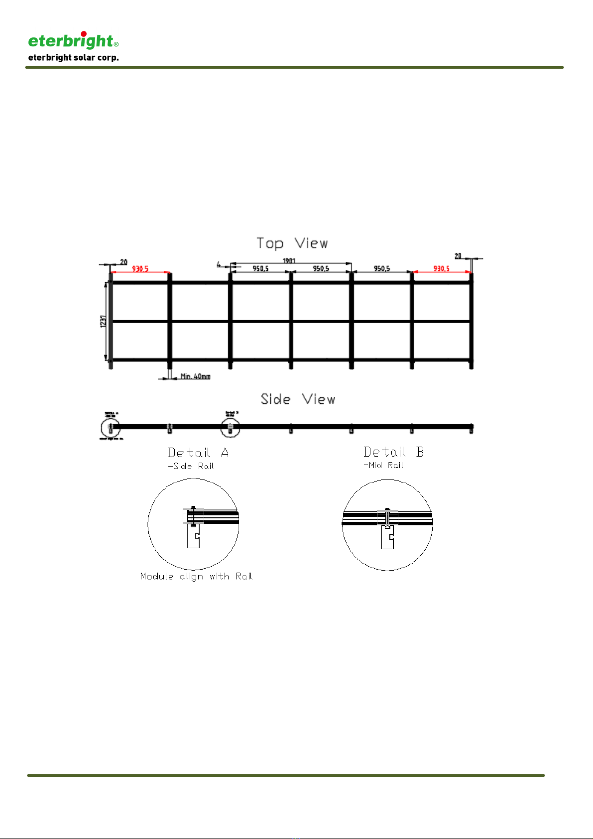
Installation and Safety Manual of CIGS-3000A1&E1 Solar Photovoltaic Module
This document and all information contained herein is the sole property of ETERBRIGHT SOLAR CORPORATIO and shall not be distributed, reproduced, or
disclosed in whole or in part without the prior written consent of ETERBRIGHT SOLAR CORPORATIO .
A3-224
load is 1600 Pa (tested to withstand 2400 Pa according to UL 1703) and to withstand
2400 Pa wind/snow load requirement according to IEC 61646.
Any module without a frame (laminate) shall not be considered to comply with the
requirements of UL 1703 unless the module is mounted with hardware that has been
tested and evaluated with the module under this standard or by a field Inspection
certifying that the installed module complies with the requirements of UL 1703.
Clamps required with M8 (5/16 in) bolts. Selected clamps, bolts, nuts and other parts
must be corrosion-resistant materials.
o mount onto the support structure has two steps. he first step, to apply torque of 10
Nm(88.5lb-in) for pre-fix the clamps and module on support structure. he second
step, to apply torque of 20 Nm(177lb-in) to secure the module to support structure,
and pay attention as the clamps CANNO touch the glass
.
Figure 8.1 he positions of the mounted clamps and supportive rails

Installation and Safety Manual of CIGS-3000A1&E1 Solar Photovoltaic Module
This document and all information contained herein is the sole property of ETERBRIGHT SOLAR CORPORATIO and shall not be distributed, reproduced, or
disclosed in whole or in part without the prior written consent of ETERBRIGHT SOLAR CORPORATIO .
A3-224
Recommended minimum clamp dimension (mm), as in following diagrams.
op Section hree-dimensional
End Clamp
Mid Clamp
M8 Bolt
8.2 Recommend the Direction of Module
he direction of module suggests vertical to the ground that can reduce the frequency of
cleaning.

Installation and Safety Manual of CIGS-3000A1&E1 Solar Photovoltaic Module
This document and all information contained herein is the sole property of ETERBRIGHT SOLAR CORPORATIO and shall not be distributed, reproduced, or
disclosed in whole or in part without the prior written consent of ETERBRIGHT SOLAR CORPORATIO .
A3-224
8.3 ilt Angle Selection
he solar cells absorb sunlight and then
transform the light energy into
electricity. o ensure that the maximum
efficiency of absorption can be
obtained, the front of the
photovoltaic module should
face the sunlight
vertically as much
as possible.
For this reason, the
optimal tilt for
the photovoltaic
module is roughly the same as the latitude of installation location.
We recommend installing the modules with a tilt angle of at least10°. o make it easier
for dust to be washed off by rain and reduce the dirt or other materials that
accumulate on the surface of photovoltaic modules.
9 Electrical Installation
Under normal conditions, a photovoltaic module is likely to produce more current and
/or voltage than reported under standard test conditions. Accordingly, the values of Isc
and Voc marked on this module should be multiplied by a factor of 1.25 when
determining component voltage ratings, conductor current ratings, fuse sizes and size
of controls connected to the photovoltaic module output.
Maximum series overcurrent protective device is 8A.
In the United States, refer to Section 690-8 of the National Electrical Code to determine
the appropriate specification of wire and fuse, which should add a multiplying factor of
1.25 (80% de-rating) from Isc.
A module with exposed conductive parts is considered to be in compliance with UL
1703 only when it is electrically grounded in accordance with the instructions
presented below and the requirements of the National Electrical Code.
9.1 Electrical Installation Precautions
he cross section of the cables and the capacity of the connectors must be selected to
suit the maximum system short circuit current.
Do not carry out installation when PV modules, installation tools or installation area
are exposed to water.
Installation and Safety Manual of CIGS-3000A1&E1 Solar Photovoltaic Module
This document and all information contained herein is the sole property of ETERBRIGHT SOLAR CORPORATIO and shall not be distributed, reproduced, or
disclosed in whole or in part without the prior written consent of ETERBRIGHT SOLAR CORPORATIO .
A3-224
he system requires confirmation that the wiring is correct.
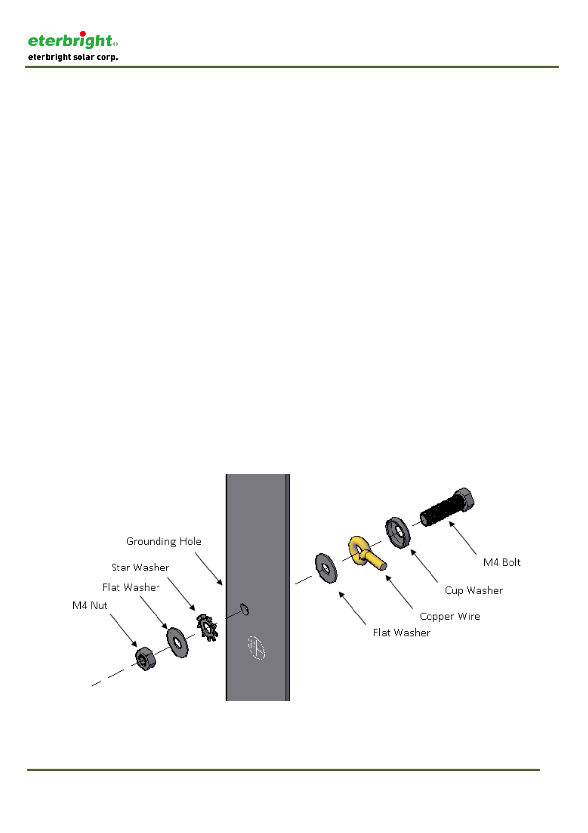
9.2 Grounding
Where common grounding hardware (nuts, bolts, star washers, spilt-ring lock washers,
flat washers and the like) is used to attach a listed grounding/bonding device, the
attachment must be made in conformance with the grounding device manufacturer’s
instructions.
he ground wire must not be smaller than No.12 AWG (4 mm²), and insulation
resistance must beat least 90°C, or according to local regulations, e.g. the NEC
(National Electric Code) in the United States.
If the building is already equipped with an exterior lightning protection system, the PV
installation must be integrated into the protection system against direct effects of
lightning.
here are six 4mm [Φ4mm] grounding holes with earth symbols
○
⏚ each on the long
frame of module; the module frame MUS BE properly grounded.
Use an M4 stainless steel bolt and pass through a diameter M4 stainless steel cup-
washer, use the 12AWG(4mm²) copper wire wound on the bolt, then pass it through
theM4stainless steel flat washer, and place the bolt through the grounding hole of the
frame, M4 stainlessstarwasher,M4stainless steel flat washer, and finally with a M4 nut
use about3 ~ 4Nm (22.1 ~ 22.6 lb-in)of torque to lock onto the frame.
Common hardware items such as nuts, bolts, star washers, lock washers and the like
have not been evaluated for electrical conductivity or for use as grounding devices and

Installation and Safety Manual of CIGS-3000A1&E1 Solar Photovoltaic Module
This document and all information contained herein is the sole property of ETERBRIGHT SOLAR CORPORATIO and shall not be distributed, reproduced, or
disclosed in whole or in part without the prior written consent of ETERBRIGHT SOLAR CORPORATIO .
A3-224
should be used only for maintaining mechanical connections and holding electrical
grounding devices in the proper position for electrical conductivity. Such devices,
where supplied with the module and evaluated through the requirements in UL 1703,
may be used for grounding connections in accordance with the instructions provided
with the module
9.3 Electrical Wiring
he cables have connectors for an electrical connection system.
he module cables should be fixed onto the module frame or support in order to avoid
any stress to the connector.
he cables should avoid exposure to direct sunlight.
he junction box CANNO be opened or destroyed, and the place of installation should
avoid rain.
Recommended number of installed modules:
Calculated under condition of +10% tolerance of Voc at S C. he sum of Voc of
series modules must NO exceed the maximum system voltage under any
condition.
he number of series and parallel MUS CONSIDER the capabilities of inverter.
△
!Warning: Electrical hazard, DON’ OUCH bare conductors, wire or other energized
parts.

Installation and Safety Manual of CIGS-3000A1&E1 Solar Photovoltaic Module
This document and all information contained herein is the sole property of ETERBRIGHT SOLAR CORPORATIO and shall not be distributed, reproduced, or
disclosed in whole or in part without the prior written consent of ETERBRIGHT SOLAR CORPORATIO .
A3-224
9.4 Start Generation System
For a photovoltaic generation system connected to the power grid, you MUS
CONFIRM that the system has passed the inspection, testing and shall comply with
regulatory requirements.
10 Maintenance
Clean the glass surface of the module when required. Always use clean water and a
soft sponge or cloth for cleaning.
It is recommended to check the electrical, grounding and mechanical connections
every six months or shorter to verify that they are clean, secure, undamaged and free
of corrosion.
When replacement parts are required, the installer or servicer should ensure that parts
uses are specified by the manufacturer, with the same characteristics as the original
parts. Unauthorized substitutions may result in fire, electric shock, or other hazard.
At the suitable moment, maintain the parts used in the system, such as brackets,
charging rectifiers, inverters, batteries, etc.
11 Shut Down Generation System
o prevent the generation of electricity during disassembly of the conductor, an
opaque material must be used to COMPLE ELY cover the photovoltaic module.
In disconnecting the system from the power grid, each component used in the
system must comply with the operating instructions.
After the system stops running, it then can be disassembled. During operation,
comply with ALL applicable safety of installation guides.

Installation and Safety Manual of CIGS-3000A1&E1 Solar Photovoltaic Module
This document and all information contained herein is the sole property of ETERBRIGHT SOLAR CORPORATIO and shall not be distributed, reproduced, or
disclosed in whole or in part without the prior written consent of ETERBRIGHT SOLAR CORPORATIO .
A3-224
12 Revision History
Version Details Release Date
A Initial Release 2015.09.09
B Add Power Grade 2015.09.25
C
1.Correct 6.3 thermal characteristics and 6.4 front
cover
2.Update 6.6 Module Physical Specifications
3.Add 8.2 Direction of Module
2015.12.15
D Change Name of Company 2016.08.04
1.0 Add Power Grade 2017.11.15
1.1
Update 6.1 Electrical Characteristics
Chapter 9, add maximum series overcurrent
protective device
2018.12.21
1
.2
Update the name of product from Cigs-3000A1 &
Cigs-3000E1 to CIGS-3000A1 & CIGS-3000E1 2019.6.20
This manual suits for next models
33
Table of contents


/F-B installation manual")


