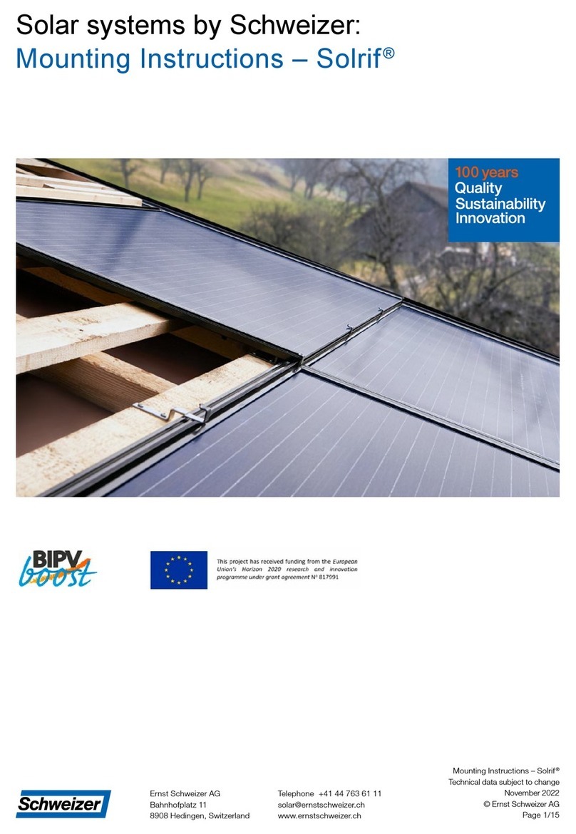
SILLIA 60P Series Quick start guide

Page 1 sur 8
Document NI0003_V04 : Installation note for solar panels with the Solrif frame
SILLIA Energie –4 Avenue Pierre Marzin 22303 LANNION Cedex –France
Tel : +33 (0)2 96 05 80 50
1. Introduction
2. Safety
3. Installation and electrical connection
4. Maintenance and servicing
5. Electrical characteristics
Document subject to technical changes. The latest version can be downloaded from our website:
www.sillia.com. These instructions deal only with the installation of photovoltaic modules. To install
Solrif framed modules with the SILLIA Confort integration structure please revert to the specific
installation note also available from our website: www.sillia.com.
Installation note for solar panels with the Solrif frame
French manufacturer of solar panels
1/
3
20
13
March

Page 2 sur 8
Document NI0003_V04 : Installation note for solar panels with the Solrif frame
SILLIA Energie –4 Avenue Pierre Marzin 22303 LANNION Cedex –France
Tel : +33 (0)2 96 05 80 50
1. Introduction
1.1 Description :
These instructions deal only with the following products: 60PXXX, 50PXXX, 60MXXX, 55MXXX,
48MXXX, 60QcellsXXX and 50QcellsXXX.
1.2 Service manual :
This manual describes the mounting and electrical connection of SILLIA Energie’s modules in a
photovoltaic field. Any installation must follow the rules described in this document.
Those instructions are intended for fitters, developers and people designated by the developer. All
the staff performing the installation of the photovoltaic modules must have the qualifications
required for solar panels roof installation.
1.3 Certification :
Modules SILLIA Energie are certified :
IEC 61215 Edition 2
IEC 61730 -1 et 2 class A (protection class II)
1.4 Warranty :
SILLIA Energie General Terms and condition (GTC) and warranty conditions shall apply.
1.5 Storage and Handling :
The modules must be stocked in a ventilated and dry area.
Handle the modules by the frame, two persons or more are needed.
Do not handle the modules by the connection cables.
Do not walk on the modules.
Do not use tools that may damage the back faces or front faces of the modules.
2. Safety
2.1 Obligations and conditions for the operator and installer:
The operator and the installer must ensure that:
The standards and the current national directives are respected,
The mounting is realized by persons having the knowledge required,
The electrical connection is realized by professionals in electronics,
The professionals in charge of the installation can estimate the tasks as well as the possible
dangers associated to a photovoltaic plant,
Assembling instructions are an integral part of the product and must be available during the
installation.

Page 3 sur 8
Document NI0003_V04 : Installation note for solar panels with the Solrif frame
SILLIA Energie –4 Avenue Pierre Marzin 22303 LANNION Cedex –France
Tel : +33 (0)2 96 05 80 50
The mounting and security instructions are known by all the operators before proceeding to
the installation.
The installation and handling tools are adapted to the realization of solar panels installation.
Only components designed to be used in photovoltaic plants installation should be used.
In case of exchange, only SILLIA Energie components must be used.
Modules are never stocked near gas or near flammable products.
No artificial solar light must be concentrated on the module.
The module is not dismantled. No part included in the module must be removed.
2.2 Safety instructions
Safety instructions mentioned below are an integral part of the mounting instructions and
are important for the handling of the modules.
Make sure that the weight of the PV panels is compatible with the integration structure.
Verify the mechanical integrity of the SILLIA Energie modules before the mounting (modules
must be in perfect conditions).
Use adapted fixation systems which can support additional occasional loads (ex: snow, strong
wind…).
Be sure that the other components of the system have no mechanical or electric impact on
the photovoltaic modules.
Work in a dry environment with dry modules and tools.
No hole in the glass or in the aluminum frames should be made.
Keep a copy of this document close to the photovoltaic plant
3 Mounting
3.1 General installation instructions :
Ensure that all the current standards, constructive arrangements and regulations related to
accidents prevention are respected
The support of assembly must be made of materials compatible with the aluminum of the
Solrif frame of the SILLIA Energie modules.
Use an installation solution which allows the passage of air in sufficient quantity (SILLIA
Energie recommends an air gap of 20 mm underneath the modules with SOLRIF frame).
3.2 Fixation of the SILLIA Energie modules
The installation has to be in compliance with the recommendations of the suppliers of the
photovoltaic system fixations.
Secure the modules against sliding and fall risks.
Do not drop the modules.
Do not drop anything on modules.
Do not walk on modules.
Two persons situated on opposite sides of the frame are needed to manipulate the modules.

Page 4 sur 8
Document NI0003_V04 : Installation note for solar panels with the Solrif frame
SILLIA Energie –4 Avenue Pierre Marzin 22303 LANNION Cedex –France
Tel : +33 (0)2 96 05 80 50
3.2.1 Installation of SILLIA Energie modules :
The SILLIA Energie photovoltaic modules fitted with a Solrif frame can be installed only in a landscape
mode. Solar panels can be installed according to the sequences of installation presented below, it is a
guarantee of safety, practicability and quality.
Places of use :
roof presenting a slope between 15 ° and 65 °,
only on buildings with low hygrometry,
Only on parts of the roof without going up to the roofing edges, nor the ridge or the
drainage.
as a replacement of small elements of cover (tiles or slates) and on a wood framework,
on a roof with a maximum 600mm spacing between rafters,
installation necessarily done, in all cases, with underlays being placed all over the area
covered by photovoltaic modules. The underlays will be HVP breathing, homologated roof
cover by CSTB with a E1-Sd1-Tr2 classification or under technical advice with W1
classification according to norm EN 13859-1 or equivalent.
3.2.1.1 Installation of the first row of hooks :
To assure the fixation of the PV modules, 3 types of hooks are supplied. "Glass”and "Side”hooks are
used in the common part of the photovoltaic field while "Top”hooks are only used to fix the last row
of solar panels.
"Glass” hooks fitted with a
plastic muff.
"Side” hooks
"Top” hooks

Page 5 sur 8
Document NI0003_V04 : Installation note for solar panels with the Solrif frame
SILLIA Energie –4 Avenue Pierre Marzin 22303 LANNION Cedex –France
Tel : +33 (0)2 96 05 80 50
SILLIA Energie recommends a minimal number of hooks to be installed, depending on the size of the
solar panel :
60 cells
(1705 x 1023)
50 cells
(1682 x 864)
48 cells
(1377 x 1023)
"Side”hooks
2
2
2
"Glass” hooks
3
3
2
Total fixing points /panel
5
5
4
The implementation of the hooks has to be made from the bottom to the top and from the right to
the left :
Fix the first and the last "Side”mounting straps of the first row of solar panels with two
stainless screws 4,5x35 (flat cylindrical head). Use the same type of screws for all the hooks.
Stretch a chalk line between those two hooks.
Take for reference the upper hole of the hooks. Use the same reference point to avoid gaps
between quotations.
Fix the other hooks of the lower row.
3.2.1.2 Installation of the first module :
Insert the first module into the hooks on the right of the lower row.
Make sure that the frame recesses are facing upward.
Prepare the cables of the module to allow its connection with the following
module.
Link the finishing pieces with the frame of the module. Verify that the
"Side”hook rests exactly in the recesses of the frame.
3.2.1.3 Installation of the second module:
-Place the right profile of the module in the
left profile of the previous module (cf.
detail 1).
-Slide the module to the full in the “glass”
hooks.
-Assemble profile against profile: make sure
the modules are aligned with a 2mm gap
(cf detail 2).
-Connect the cables of the modules
together making sure no cable get stuck
between mounting straps and modules.
Detail 2
Detail 1

Page 6 sur 8
Document NI0003_V04 : Installation note for solar panels with the Solrif frame
SILLIA Energie –4 Avenue Pierre Marzin 22303 LANNION Cedex –France
Tel : +33 (0)2 96 05 80 50
3.2.1.4 Installation of the second row of hooks:
3.2.1.3 Pose de la seconde rangée de crochets :
Repeat these operations for every row of modules. For the last one, "Side”hooks and "Glass” hooks
are to be replaced by "Top”hooks.
3.2.2 Electrical connection (Danger of death by electrocution ! ) :
In normal conditions, a photovoltaic module may produce currents and\or tensions superior to those
given in normalized test conditions (STC). The values Isc and Voc marked on this module have to be
multiplied by a factor of 1.25 for the tension and current sizing of the components. This point is also
important for the sizing of fuses and commands connected to the exits of the photovoltaic module.
Be sure that cables and connections are in accordance with the current prescriptions and are
not damaged.
Protect cables against any damage.
The solar modules must not be in contact with stagnant water
Electrical connections must not be located on the flow of the water
SILLIA Energie recommends avoiding that the parts assuring the pressure on the cables of the
junction box may be facing upward in the direction of the water flow.
Caution : danger due to continuous electricity! Risk of important burns and wounds by
electric arc!
Do not disconnect the connections when the system is in charge (electricity is being
produced).
Ensure a sufficient protection to avoid any contact with conductive parts.
Only use tools which are electrically isolated.
3.2. 3 Wiring :
SILLIA Energie modules are designed for a serial wiring.
Detail 1
-Fix the hooks of the second row above the
row of modules already installed.
-Use a template allowing to keep a 15mm
space between the hooks and modules
previously installed (cf. detail 1.).

Page 7 sur 8
Document NI0003_V04 : Installation note for solar panels with the Solrif frame
SILLIA Energie –4 Avenue Pierre Marzin 22303 LANNION Cedex –France
Tel : +33 (0)2 96 05 80 50
The solar cable to be used has to be of section 4.00 mm ² and be of solar quality.
During module serial connection, make sure that the polarity of the connection is correct.
Exemple :
3.2.4 Earthing
The SILLIA Energie solar panels with a Solrif frame must be connected to the earth according to the
prescriptions and current standards.
To ensure that the grounding connections are properly made, proceed as follows :
-to fix the cable on the upper frame holes, use self-tapping stainless steel screws with a 4.2 diameter
and 13 mm length ( see illustrations above).
- to avoid any screw loosening following the installation of the grounding cables on the upper frame
you must use stainless steel serrated lock washers with a 4 mm diameter.
4. Maintenance and servicing
-SILLIA Energie modules require very little maintenance.

Page 8 sur 8
Document NI0003_V04 : Installation note for solar panels with the Solrif frame
SILLIA Energie –4 Avenue Pierre Marzin 22303 LANNION Cedex –France
Tel : +33 (0)2 96 05 80 50
- A periodic cleaning of the modules is recommended to assure an optimal functioning of the solar
generator.
-A slope superior to 10 ° is recommended to guarantee an auto cleaning obtained by the streaming
of water rains.
During cleaning of modules:
-Use exclusively a neutral cleaning liquid, not abrasive and not corrosive.
-Use water at a temperature equivalent to that of the module.
-Wipe the module surface with water and a soft and appropriate cloth.
-
5 Electrical Characteristics
The technical characteristics of the modules are available on our website: www.sillia.com.
The maximal number of modules (60PXXXX / 60MXXX / 60QcellsXXX) that could be installed in series
is 22.
The maximal number of modules (48MXXX) that could be installed in series is 26.
A protection by fuses against overcurrents may be needed. Revert to current norms and national
directives. SILLIA recommends against the overload a protection fuse of 15A maximum.
This manual suits for next models
6
Table of contents
Popular Solar Panel manuals by other brands

First Solar
First Solar CuRe 6 Series user guide
Clenergy
Clenergy PV-ezRack SolarTerrace II-A manual

Nature Power
Nature Power 50042 installation manual

Solar Technology International
Solar Technology International PV Logic MHD Flexi user manual
Sonnenkraft
Sonnenkraft SS20 manual
SolaX Power
SolaX Power X3-Matebox basic Quick installation guide
