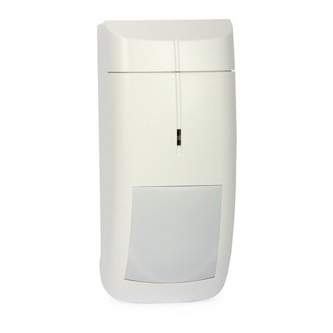
Etlin-Daniels SENPIR-CM-02 User manual

SAVE THESE INSTRUCTIONS - READ ALL INSTRUCTIONS CAREFULLY
WARNING
AVOIDING HVAC TURBULENCE
WHEN USING ELECTRICAL DEVICES, SAFETY PRECAUTIONS SHOULD ALWAYS BE FOLLOWED.
• Disconnect power to the sensor by turning OFF the circuit breaker or removing the fuse from
the circuit before installing the SENPIR-CM-01 PIR Occupancy Sensor.
• CAUTION – FOR YOUR SAFETY: IF YOU ARE NOT SURE ABOUT ANY PART OF THESE
INSTRUCTIONS, CONSULT A QUALIFIED ELECTRICIAN.
When Heating, Ventilating or Air Conditioning (HVAC) units are turn on, they create
turbulence which can cause the sensor to activate. It is important that the sensor and HAVC
unit be separated by 6ft.
If the sensor’s location gives it a view of other rooms or hallways, the load will turn on when
movement is detected in these adjacent areas. The sensor’s detection zone may be restricted
by masking a portion of the lens.
In addition, it is also recommended NOT to mount the SENPIR-CM-02 PIR Occupancy Sensor
directly under a large light source. Large wattage bulbs (greater than 100W incandescent)
give off a lot of heat and switching the bulbs causes a temperature change that can be
detected by the device. Mount the SENPIR-CM-02 PIR Occupancy Sensor at least 6ft away
from large bulbs.
The sensor detects changes in the infrared energy given off by the occupants as they move
within the coverage area. When occupancy is detected, a self-contained relay switches the
connection load on. The sensor is line powered and can pass-thru the line voltage (Refer to
Max load for limitation). An internal timer automatically turns off the load after a selectable
period of inactivity.
The sensor’s relay is shipped in a closed position that turns the load on upon initial power-up.
The connected load will stay on for about 80 seconds to allow PIR sensor to initialize.
• Designed for 12 to 18 ft (3m to 4.5m) mounting heights.
• 12 to 24 ft (3 to 6.1m) radial coverage overlaps area lit by a typical high bay fixture.
NOTE: The coverage data is measured under the best temperature condition (20 - 25), and a
higher temperature may not lead to an ideal coverage.
The “TIME” knob sets the ON time of the load after inactivity. The time is reloaded after each
detection. Turn the adjustment knob fully counter clockwise to the minimum setting (Marked
1 TEST) to have short delay time and test the sensor. The delay for TEST mode is 15 seconds.
You can select your preferred setting by adjusting the knob to the desired time (5,10,20 or 30
minutes).
The “SENSE” knob sets the sensitivity of the occupancy detection.
The knob is adjustable from 50% (Position 1) to 100% (Posiiton 5) Turning the knob
clockwise will increase the sensitivity while turning it counter-clockwise will decrease it.
The “LIGHT” knob sets the threshold of the ambient light necessary to activate the load. Your
load will only turn on if the natural lighting in the room is low.
If the low lighting feature is not desired, position the know on the maximum setting (Position
5). This will allow the occupancy sensor to turn on the load regardless of the ambient lighting
condition.
SENSOR INSTALLATION
SENSOR OPERATION
INITIAL POWER UP (80 SECONDS WARM UP)
COVERAGE AREA
TIMEOUT KNOB
SENSITIVITY KNOB
AMBIENT LIGHT LEVEL KNOB
WIRING DIAGRAM
SENSOR ADJUSTMENT/PROGRAMMING
1. Turn off Circuit Breaker
2. Determine the best location for the sensor. Install the sensor at least 3ft. away from
fluorescent ballasts and HVAC ducts, and at least 4ft. away from incandescent fixtures and
HVAC diffusers.
3. Connect wires as per the WIRING DIAGRAM as follows:
BLACK lead to LINE (HOT); RED lead to LOAD; WHITE lead to NEUTRAL.
Twist the existing wires together with the wire leads of the sensor as shown in the wiring
diagram. Cap them securely using the wire nuts provided.
4. Remove the Sensor’s back plate by holding the plate and twisting the sensor counter-clockwise.
5. Secure the back plate with the standard Ceilling box using the two screws provided.
(see figure# 1.)
6. Mount the sensor with the plate. Restore power at circuit breaker or fuse box.
INSTALLATION MANUAL FOR SENPIR-CM-02 PIR OCCUPANCY SENSOR
gure #1
HOT (BLACK)
NEUTRAL (WHITE) WHITE
WHITE
SENSOR
LINE
120-277VAC
60HZ
BLACK
BLACK
RED
LOAD
Head Ofce - 1850 Wilson Ave. · Toronto, ON · M9M 1A1 · Tel: 416.741.7336 · Fax: 416.741.9104
Toll Free: in Canada. 1.800.661.9610 · in USA. 1.888.762.5384 (SOCKETS4U)

SAVE THESE INSTRUCTIONS - READ ALL INSTRUCTIONS CAREFULLY
TROUBLESHOOTING
LIGHTS WILL NOT TURN ON
• Circuit breaker or fuse is OFF: Turn the breaker ON.
Ensure the lights being controlled are in working order (i.e., working bulbs, ballasts, etc.)
• Sensor is wired incorrectly or may be defective: Confirm that the sensor’s wiring is correct
and there are no problems visually.
• Lens is dirty or obstructed: Inspect the lens visually and clean if necessary.
LIGHTS WILL NOT TURN OFF
• Make sure no motion is occuring in the coverage area during the 15 sec. delay (in “TEST”
Timeout).Sensor is wired incorrectly or may be defective: Confirm that the sensor’s wiring is
correct and there are no problems visually.
• Sensor may be mounted too closely to an air conditioning or heating vent.
• The line voltage has dropped: Perform the necessary tests to ensure the line voltage has not
dropped beneath 100V.
LIGHTS TURN OFF AND ON TOO QUICKLY
• Sensor may be mounted too closely to an air conditioning or heating vent.
• Time delay set improperly: Refer to TIME DELAY Adjustment guide.
INSTALLATION MANUAL FOR SENPIR-CM-02 PIR OCCUPANCY SENSOR
Head Ofce - 1850 Wilson Ave. · Toronto, ON · M9M 1A1 · Tel: 416.741.7336 · Fax: 416.741.9104
Toll Free: in Canada. 1.800.661.9610 · in USA. 1.888.762.5384 (SOCKETS4U)
Table of contents
Popular Security Sensor manuals by other brands

Visonic
Visonic DISCOVERY PIR MCW - INSTALLER GUIDE installation instructions

SKF
SKF Lincoln 254-15165-9 Service manual

UbiTech
UbiTech WWDLW Series user manual

3M
3M Dynatel 2273M-iD Series Operator's manual

EMX Industries
EMX Industries MVP D-TEK instruction manual
Pfeiffer Vacuum
Pfeiffer Vacuum ASM 310 operating instructions
