®
IVORY
PASSIVE INFRARED DETECTOR
WITH MIRROR OPTICS
ivory_en 08/08
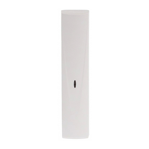
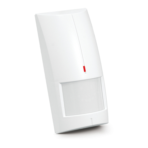
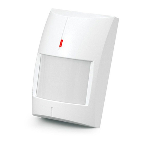
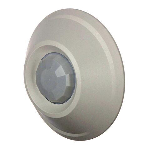
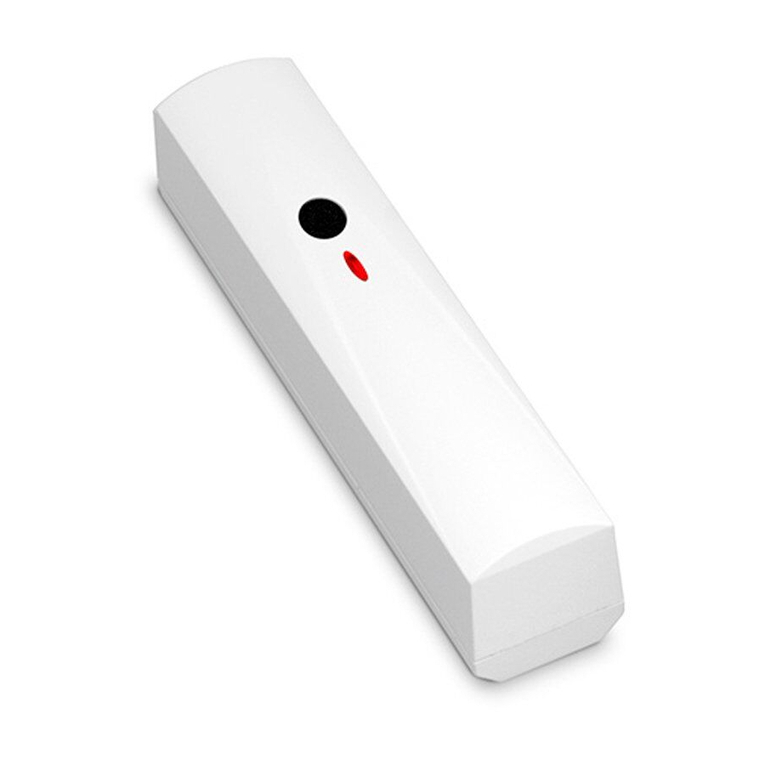
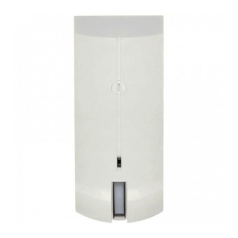
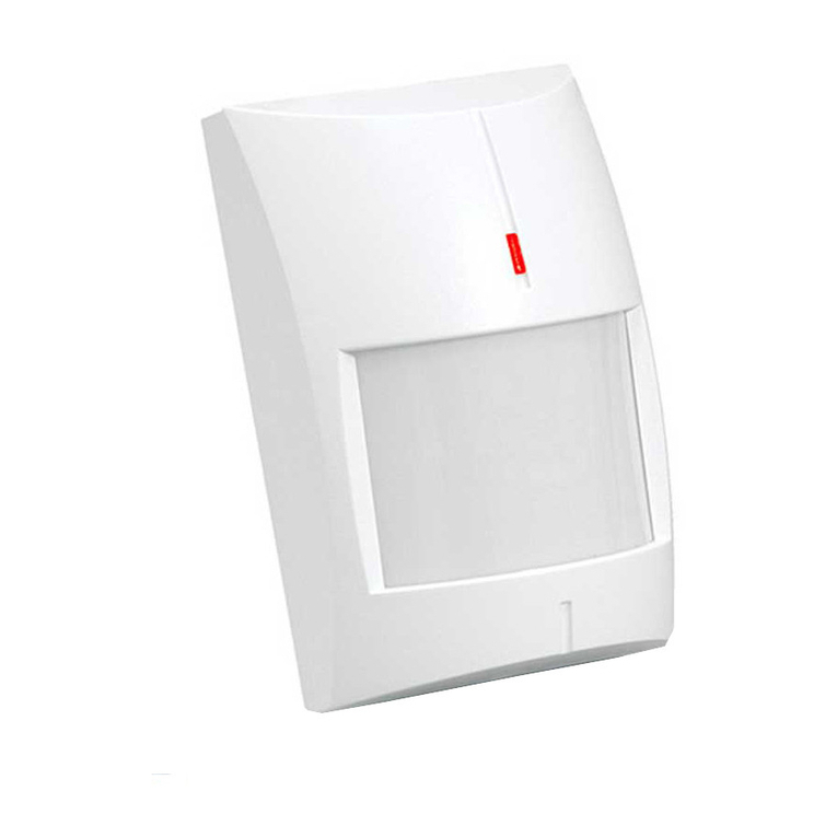
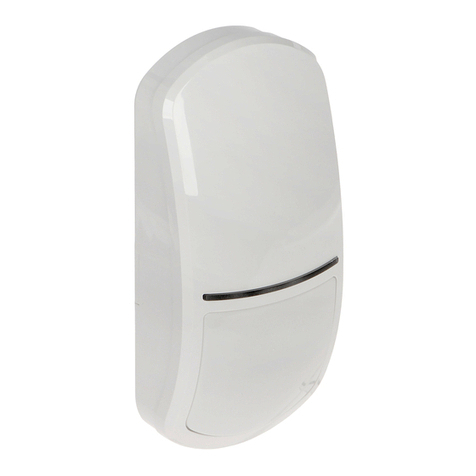
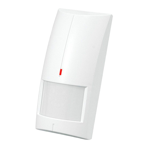
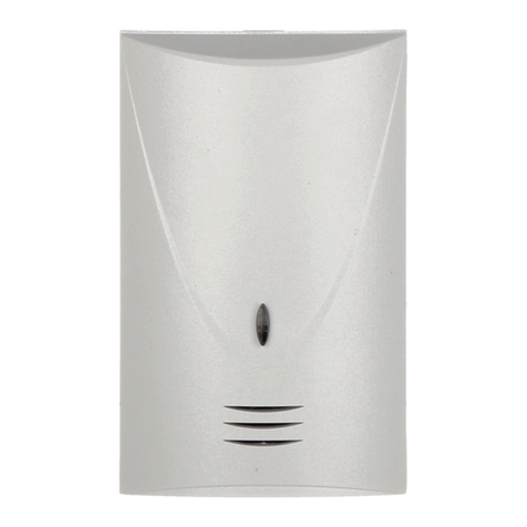
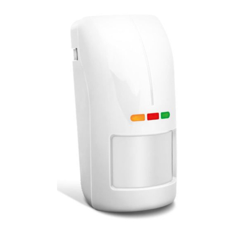
The IVORY motion detector is a dedicated device for burglary and panic alarm
systems. Its optical system is based on a high-quality segmented mirror, which
ensures the same sensitivity within the entire monitored area and eliminates the
so-called dead zone. The use of a precision optical path and an advanced signal
processor has made it possible to obtain a very high sensitivity as well as
immunity to false alarms. An advanced digital temperature compensation feature
enables operation within a wide range of temperatures. Other advantages of the
detector include alarm memory and remote on/off switching of the LED indicator.
1
1
2
4
3
Explanations for Figure 1:
1 - fixing pins for terminal block. Description of terminals:
NC - relay (NC).
TMP - tamper switch.
COM - common ground.
12V - power input.
LED - the input enables the LED indicator to be remotely switched
ON/OFF, if the jumper is removed from the LED ON/OFF pins.
The LED will signal violations, when the LED input is short-circuited
to the common ground. For control of the input, you can use the OC
type output of the control panel, programmed e.g. as SERVICE
MODE INDICATOR or BI SWITCH.
MEM - the alarm memory control input. It is required that the OC type
output of the alarm control panel, programmed as ARMED STATUS
INDICATOR be connected to the input. When the input is shorted to
the ground and the detector registers a motion, thus triggering the
alarm, the LED blinking will signal the alarm memory. The alarm
memory signaling will continue until the input is shorted to the
ground again. Cut-off of the input from the ground (disarming) will
not erase of the alarm memory.
2 - potentiometer for detector sensitivity adjustment.
3 - LED ON/OFF pins. Setting the jumper will activate signaling by means of the
LED, irrespective of the LED input status.
4 - pyroelement.
For 30 seconds after power-up, the detector remains in the starting state, which
is signaled by alternate blinking of the indicator LED. Only after this time has
elapsed, the detector will be ready to work.
Once motion has been sensed by the detector, the relay contacts will open for
approx. 2 seconds. This will be accompanied by lighting of the LED, which
makes it easier for the installer to check the detector for correct functioning and
to roughly determine the protected area. Blinking of the LED will signal alarm
memory.
The detector is monitoring power supply voltage and availability of the signal path.
In case of a voltage drop below 9V (±5%), lasting longer than 2 seconds, or if
a fault is found in the signal path, the detector will signal a trouble by activating the
alarm relay and steady lighting of the LED. The signaling will continue as long as
the trouble exists.
Installation
The mirror requires no cleaning. The sealed structure of the optical
chamber ensures its dust-proofness. Disassembling the electronics
board and the mirror is not recommended.
3
2
A B C
D E F G
3
A B C
4
A B C D
E F G
H JI
