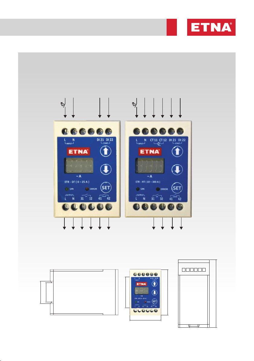
ETNA ETR-DT User manual

Electronic Thermal Relay
Product Introduction and Operation Manual

2
ATTENTION: Please read this manual carefully before using Etna Electronic Thermal Relay
1. Product Details
ETNA Electronic Thermal Relay offers protection based on the programmed limits for current value
and switch number. It is a protection element with single pole and electronic current control, which
is exclusively designed for starting electric motors. It measures the drawn current with an internal
current transformer within the relay or an external current transformer within the panel used for high-
powered motors, and enables instant monitoring of the current with the integrated 7-segment LED
display. It notifies the operating and error status with LED lamps and dry contacts. The error history
can be monitored, the low and high current limits , the maximum number of switches allowed per
hour , the delay time based on low and high current limits can be adjusted, the low and high current
automatic reset programs can be enabled or disabled using the menu. The parameters can be set
easily using 'Up, Down' and 'Set' buttons.
Two versions of Etna electronic thermal relay are available.
1- ETR – DT (Electronic thermal relay with internal current transformer): In this version, the current
transformer is included in the relay and it is designed to measure and provide protection in the
applications ranging from 0 to 25 Amperes.
2- ETR – HT (Electronic thermal relay with external current transformer): This version is designed to
measure and provide protection in the high current applications ranging from 10 to 300 Amperes via
the current transformer externally placed in the panel.
Figure 1. ETNA Electronic Thermal Relay - External View
ETR – DT ETR – HT
Error Warning Led Set and Menu Button
Down Button
Up Button
On Warning Led
7 Segment Display

3www.etna.com.tr
2. General Specifications
• 0 - 25A measurement range with internal current transformer (ETR-DT)
• 10 - 300A measurement range with external current transformer (ETR-HT)
• Password protection against unauthorized interventions
• User-friendly, easy-to-use menu
• 3-digit / 7-segment LED display
• 8-bit microprocessor-based design
• Operating frequency: 16Mhz
• Operating voltage: 220V 50Hz AC
• Operating temperature: -10 … +50°C
• Net relay weight: 150g
• Protection class: IP20
• 7 configurable parameters
• Measuring current and monitoring on LED display
• On and Error status LEDs
• On and Error dry contact relay outlets
• Adjustable low and high current limit values
• Adjustable delay time based on low and high current protection
• Adjustable maximum number of switches allowed per hour
• Enabling/disabling low and high current automatic reset programs
• Monitoring all error codes on LED display
• Tracking old error codes via error history menu
3. Front Panel Description
• Up / Down Buttons: Used to navigate in the menu on LED display and to increase/decrease the
numerical values. Moreover, the device can be manually reset by pressing and holding 'Up/
Down' buttons simultaneously for 2 seconds.
• Set Button: Used to access the menu and save the adjusted parameters.
• On LED: Green LED lights up when ETNA electronic thermal relay is on or “on” relay is activated.
• Error LED: Red LED lights up along with an error code on LED display when one of the activated
programs such as Low Current, High Current, Number of Switches is triggered. After the failure,
if there is an active automatic reset program for low/high current failure and the electronic relay
receives the 'start' command, red LED flashes to indicate that the error will be reset automatically
and the electronic motor will start after the set delay time. If there is no active automatic reset
program, red LED continuously lights up until the error is reset manually. If there an active
automatic reset program but the electronic relay does not receive the 'start' command, red LED
continuously lights up until the end of the period defined in the automatic reset program. The
error is reset automatically at the end of this period and red error LED is turned off, waiting in
standby until the 'start' command is received. While the error LED is on, the 'error' relay remains
active.
4. Maintenance
Disconnect the power before maintenance and use the required personal protective
equipment.
• Etna electronic thermal relay must be checked for any loose electrical connections.
• Ensure there is no abrasion, puncture or color change resulting from heating in the electrical
cables.

4
ETNA Electronic Thermal Relay displays '0.0' on the LED screen in the
standby mode when the power is on, as shown on the left-hand side. Green
On LED lights up when 'start' command is given by connecting start inlets
and the LED screen displays the current value.
Password Menu
This screen is displayed when 'set' button is pressed.
This screen requires entering the password to access the parameter setting
menu in order to prevent unauthorized access. The password is entered using
'Up/Down' and 'Set' buttons. Menu password is 132.
a. Error History Program
PAG program is the error history program.
After entering the correct password on the password screen, the PAG program
appears, as shown on the left-hand side. The error history program is accessed
by pressing 'Set’ and the number of the error order is selected using 'Up/Down'
buttons. Pressing 'set’ again displays the respective error code. The most recent
error is always moved to the top of the list. The program is closed by timeout.
b. High Current Limit Program
"PYA" program is the program in which the high current limit is set.
PYA program is accessed by pressing 'Up' button and then 'Set' button is
pressed.
After adjusting the high current limit to the required value using the 'Up/Down'
buttons, 'Set' is pressed once again to save the high current limit value. When
the measured current is over the current limit set in this program, 'High Current
(EYA)' failure is triggered, error LED lights up and error relay is activated.
5. Menu
Figure 2. Main Screen
Figure 3. Password Screen
Figure 4. Error History
Program Screen
Figure 5. High Current Limit
Program Screen
c. Low Current Limit Program
"PdA" program is the program in which the low current limit is set.
PdA program is accessed by pressing 'Up' button and then 'Set' button is
pressed.
After adjusting the low current limit to the required value using the 'Up/Down'
buttons, 'Set' is pressed once again to save the low limit value. When the
measured current is below the current limit set in this program, 'Low Current
(EdA)' failure is triggered, error LED lights up and error relay is activated.
d. Number of Switches Limit Program
"PSS" program is the program in which the maximum number of switches
allowed per hour is set. PSS program is accessed by pressing 'Up' button and
then 'Set' button is pressed. After adjusting the number of switches to the
requested value using the 'Up/Down' buttons, 'Set' is pressed once again to
save the maximum number of switches allowed per hour.
An hour (60 minutes) is divided by the set value to set the time to wait between
2 consecutive starts. For example, if PSS is set to '10' in this program, the
minimum time between starts will be 6 minutes, so a maximum of 10 starts per
hour are possible. The number of switches limit program should be adjusted
according to the power of the electric motor. It can be adjusted between 0 and
80 according to the engine power.
Figure 6. Low Current Limit
Program Screen
Figure 7. Switch Number
Limit Program Screen

5www.etna.com.tr
e. Automatic Reset Program for High Current Error
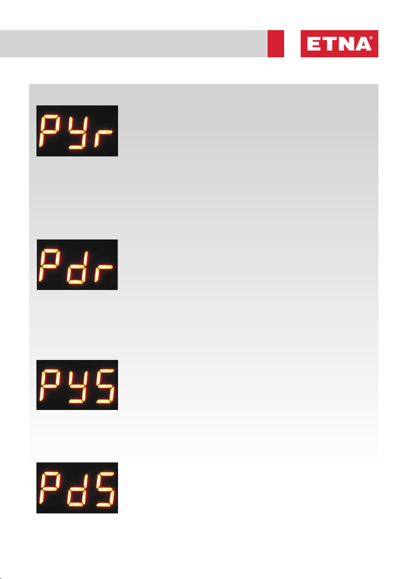
PYr program is the program in which the automatic reset scenario in high
current error in electronic relay can be enabled or disabled. PYr program
is accessed by pressing 'Up' button and then 'Set' button is pressed. The
high current automatic reset program is enabled/disabled using the 'Up/
Down' buttons. The program would be active when '1' and passive when
'0’ is selected. When the automatic reset program for high current error is
enabled, the high current error is reset automatically in increasing intervals
of 2, 5 and 8 minutes respectively once 'High Current' error is triggered. At
the end of the 3rd automatic reset, 'EbL' error is triggered and the system is
blocked, preventing automatic reset. The system requires manual reset to be
performed by pressing 'Up/Down' buttons to delete the error. The factory
setting for this program is '0' (disabled). Since high current may cause failures
in electric devices, it is not recommended to activate this program in general
applications, if not custom.
Figure 8. High Current
Reset Program Screen
f. Automatic Reset Program for Low Current Error
Pdr program is the program in which the automatic reset scenario in low
current error in electronic relay can be enabled or disabled. Pdr program
is accessed by pressing 'Up' button and then 'Set' button is pressed. The
low current automatic reset program is enabled/disabled using the 'Up/
Down' buttons. The program would be active when '1' and passive when
'0’ is selected. When the automatic reset program for low current error is
enabled, the low current error is reset automatically in increasing intervals of
2, 8, 18, 32 and 50 minutes respectively once 'Low Current' error is triggered.
If low current is received at the end of the 5th automatic reset, 'EbL' error
is triggered and system is blocked, preventing automatic reset. The system
requires manual reset to be performed by pressing 'Up/Down' buttons to
delete the error. The factory setting for this program is '1' (enabled).
Figure 9. Low Current
Reset Program Screen
h. Delay Time Program for Low Current Error
PdS program is used to set the time to wait before triggering 'Low Current'
error when a current below the set low current limit is drawn.
PdS program is accessed by pressing 'Up' button and then 'Set' button is
pressed. After adjusting the delay time in seconds to the requested value
using 'Up/Down' buttons, 'Set' is pressed once again to save the value. This
value for delay time can be set between 2-30 seconds. The factory setting for
this program is set to '10 seconds'. It is not recommended to change the set
time except for specially adjusted applications.
g. Delay Time Program for High Current Error
PYS program is used to set the time to wait before triggering 'High Current'
error, when a current over the set high current limit is drawn.
PYS program is accessed by pressing 'Up' button and then 'Set' button is
pressed.
After adjusting the delay time in seconds to the requested value using 'Up/
Down' buttons, 'Set' is pressed once again to save the value. This value for
delay time can be set between 2-15 seconds. The factory setting for this
program is set to '5 seconds'. Since high current may cause failures in electric
devices, it is not recommended to change the set time except for specially
adjusted applications.
Figure 10. High Current
Delay Time Program
Screen
Figure 11. Low Current
Delay Time Program Screen

6
6. Troubleshooting
ERROR
CODE SOLUTION
EYA
(HIGH
CURRENT
ERROR)
• Before the checks, if the relay is receiving 'start' command, first stop this command by turning
the 'start' inlet into an open circuit.
• Ensure there is no electrical or mechanical failure in the pump or the electric motor before
taking any measurement and action.
• Check the firmness of cables and terminal connections.
• Refer to error history to understand the cause of the error. Enter the password screen by
pressing the 'Set' button, enter the password using the 'Up/Down' buttons and check the error
history in the PAG program.
• Manually test the current drawn by the motor, check the current with an ammeter and compare
this value with the value displayed on the screen. Compare all currents drawn from all phases.
• After troubleshooting the failure which caused the high current error, reset EYA error by
pressing and holding 'Up/Down' buttons.
• Ensure that the system is operating properly after troubleshooting and resend start command
through the 'start' input
EDA
(LOW
CURRENT
ERROR)
• Before the checks, if the relay is receiving 'start' command, first stop this command by turning
the 'start' inlet into an open circuit.
• Ensure there is no electrical or mechanical failure in the pump or the electric motor before
taking any measurement and action.
• Check the firmness of cables and terminal connections.
• Ensure the suction/delivery valves are open in the pump system, and there is water in the
suction line and no air in the system.
• Refer to error history to understand the cause of the error. Enter the password screen by
pressing the 'Set' button, enter the password using the 'Up/Down' buttons and check the error
history in the PAG program.
• Manually test the current drawn by the motor, check the current with an ammeter and compare
this value with the value displayed on the screen. Compare all currents drawn from all phases.
• After troubleshooting the failure which caused the low current error, reset EDA error by
pressing and holding 'Up/Down' buttons.
• Ensure that the system is operating properly after troubleshooting and resend start command
through the 'start' input
ESS
(NUMBER
OF SWITCH-
ES ERROR)
• ESS error is triggered when the maximum number of switches allowed per hour set in the
PSS program is exceeded.
• Check the value set in PSS program.
• This error will be reset and deleted at the end of the period defined based on the value set
in PSS.
• Press and hold 'Up/Down' buttons simultaneously if manual reset is required after
troubleshooting.
EBL
(BLOCKED)
• EbL error is triggered at the end of the automatic reset trial count defined in PYr and Pdr
programs.
• Before the checks, if the relay is receiving 'start' command, first stop this command by
turning the 'start' inlet into an open circuit.
• Ensure there is no electrical or mechanical failure in the pump or the electric motor before
taking any measurement and action.
• Identify the reason for EdA (low current) or EYA (high current) error.
• Follow the steps in the EdA (low current) and EYA (high current) troubleshooting sections
and identify the reason for the EdA or EYA error.
• Press and hold 'Up/Down' buttons simultaneously to reset the EbL (blocked) error manually
after troubleshooting.
• Ensure that the system is operating properly after troubleshooting and resend start
command through the 'start' input

7www.etna.com.tr
7. Connection Diagrams
Figure 12. ETR Connection Diagrams
ON
L N
LCT11 DI 21 DI 22CT 12N
31 32 41 42
ERROR
ETR - HT ( 10 - 300 A )
OUTPUT
INPUT
ON ERROR
~ A
SET
START
ON
L N
L DI 21 DI 22N
31 32 41 42
ERROR
ETR - DT ( 0 - 25 A )
OUTPUT
INPUT
ON ERROR
~ A
SET
START
POWER
OUTPUT
ON RELAY
OUTPUT
ERROR
RELAY
OUTPUT
ON RELAY
OUTPUT
ERROR
RELAY
OUTPUT
POWER
INPUT
STA RT
INPUT
ETR-DT with Internal Current Transformer ETR-HT with External Current Transformer
STA RT
INPUT
CURRENT
TRANSFORMER
INPUT
POWER
INPUT
Figure 13. ETR Dimensions
36
110
31
50
73.5
50.3

Dudullu Organize Sanayi Bölgesi 2. Cadde No: 14
34775 Ümraniye-Istanbul / Turkey
Tel : +90 216 561 47 74 (Pbx) • Fax : +90 216 561 47 50
Rev. 06/2021
This manual suits for next models
1
Table of contents