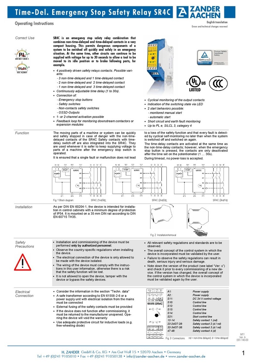
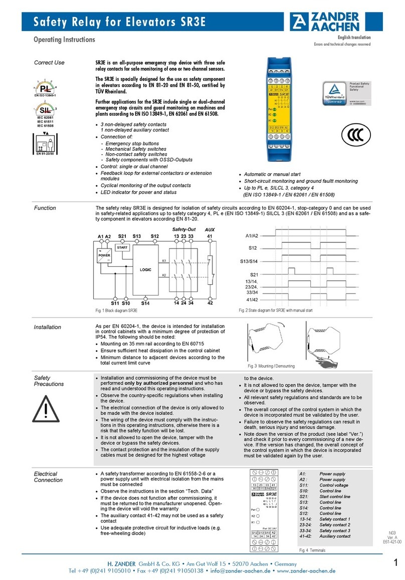
Zander Aachen MVisio HMI Pro User manual

1
H. ZANDER GmbH & Co. KG • Am Gut Wolf 15 • 52070 Aachen • Germany
Tel +49 241 9105010 • Fax +49 241 91050138 • info@zander-aachen.de • www.zander-aachen.de
M06
E61-454-00
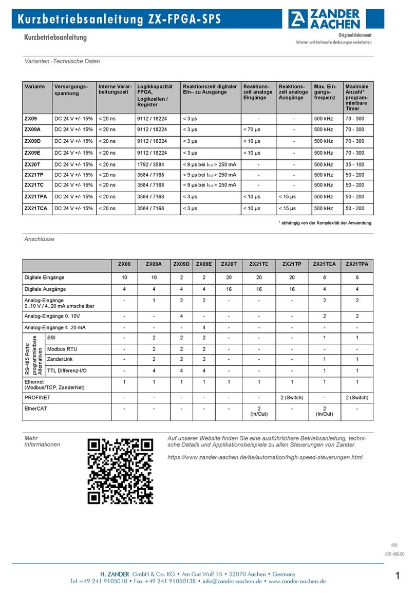
Display MVisio HMI Pro (5“-Variante) MVisio HMI Pro (7“-Variante)
Touchscreen Technologie Kapazitiv Kapazitiv
Display / backlight TFT Color / LED TFT Color / LED
Farben 64 000 64 000
Auflösung 800 x 480 800 x 480
Diagonale (Inches) 57
Format 16:9 16:9
Dimmen Ja Ja
Technische Daten
Anschlüsse MVisio HMI Pro (5“-Variante) MVisio HMI Pro (7“-Variante)
Serieller Anschluss Softwarekonfigurierbar
RS232, RS485, RS422
Softwarekonfigurierbar
RS232, RS485, RS422
Ethernet Anschluss 2x RJ45, 10/100 Mbit, separiert 3x RJ45, 2x 10/100 Mbit,
1x 10/100/1000 Mbit
USB Anschlüsse 1x USB 2.0 2x USB 2.0
Netzanschluss:
Spannung
Strom bei 24 VDC
10 bis 32 VDC; bevorzugt
24 VDC 0.6 A
10 bis 32 VDC; bevorzugt
24 VDC 0.7A
SD-Kartenslot 1x 1x
Erweiterungssteckplatz Steckplatz für eine MVisio I/O Karte Steckplatz für eine MVisio I/O Karte
Produkt-
identifizierung
Bsp.:
Aufdruck Bedeutung
Typenbezeichnung MVisio HMI Pro
Modell 5 Zoll Variante
Ident-Nr. 589103
Produktionsjahr 2020
Seriennummer X999999
Herstelleradresse H. Zander GmbH & Co. KG
Am Gut Wolf 15, 52070 Aachen
www.zander-aachen.de
EU Declaration of
Conformity
Kurzbetriebsanleitung MVisio HMI Pro
Kurzbetriebsanleitung Originaldokument
Irrtümer und technische Änderungen vorbehalten
Varianten &
Zubehör
Best.-Nr. 589102 MVisio HMI Pro (7“)
Best.-Nr. 589103 MVisio HMI Pro (5“)
Zubehör:
Best.-Nr. 589105 MVisio I/O Modul
Best.-Nr. 589106 Adapter Modul
Mehr
Informationen

2
H. ZANDER GmbH & Co. KG • Am Gut Wolf 15 • 52070 Aachen • Germany
Tel +49 241 9105010 • Fax +49 241 91050138 • info@zander-aachen.de • www.zander-aachen.de
M06
E61-454-00
7“-Variante
5“-Variante
Abmessungen
Zu Ihrer Sicherheit Bestimmungsgemäße Verwendung
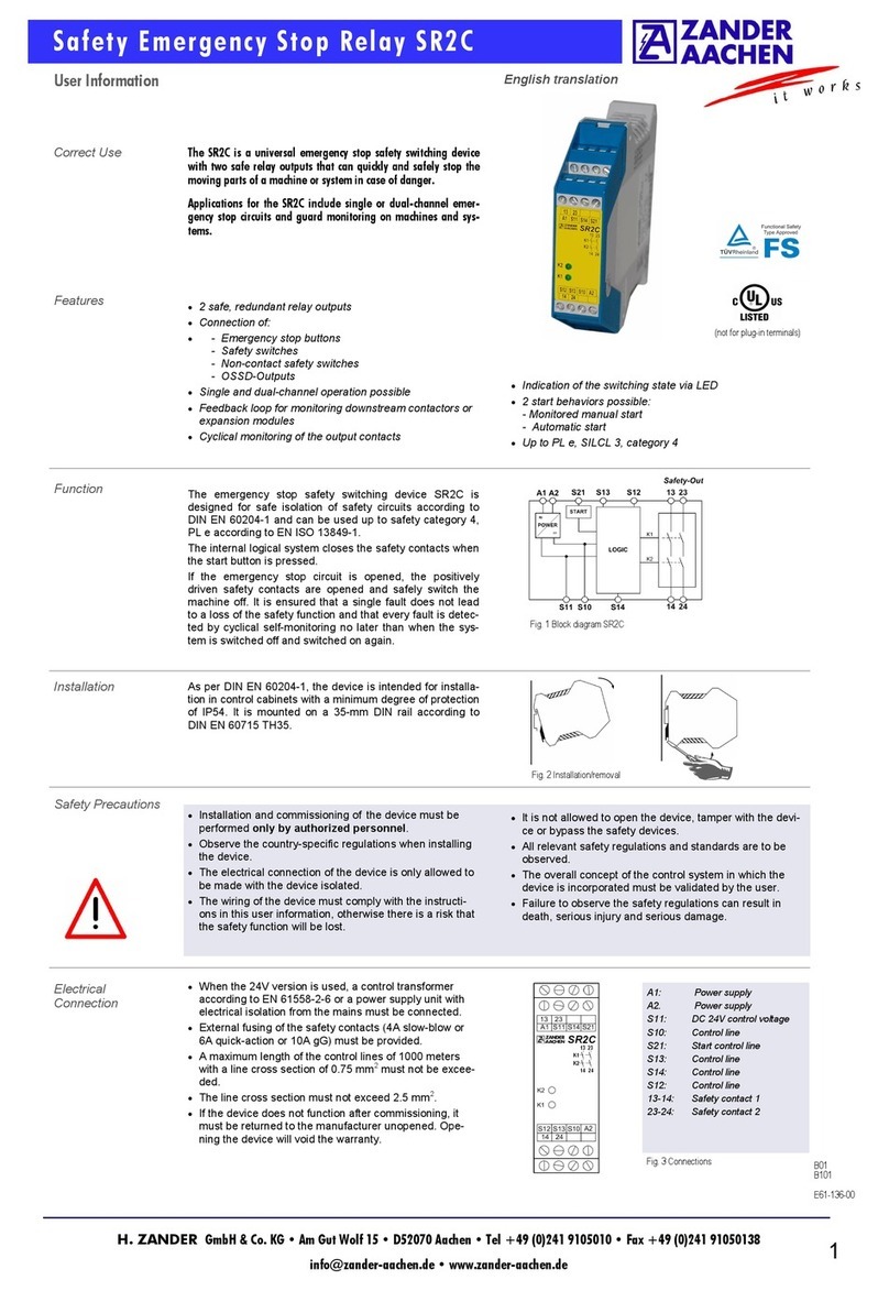
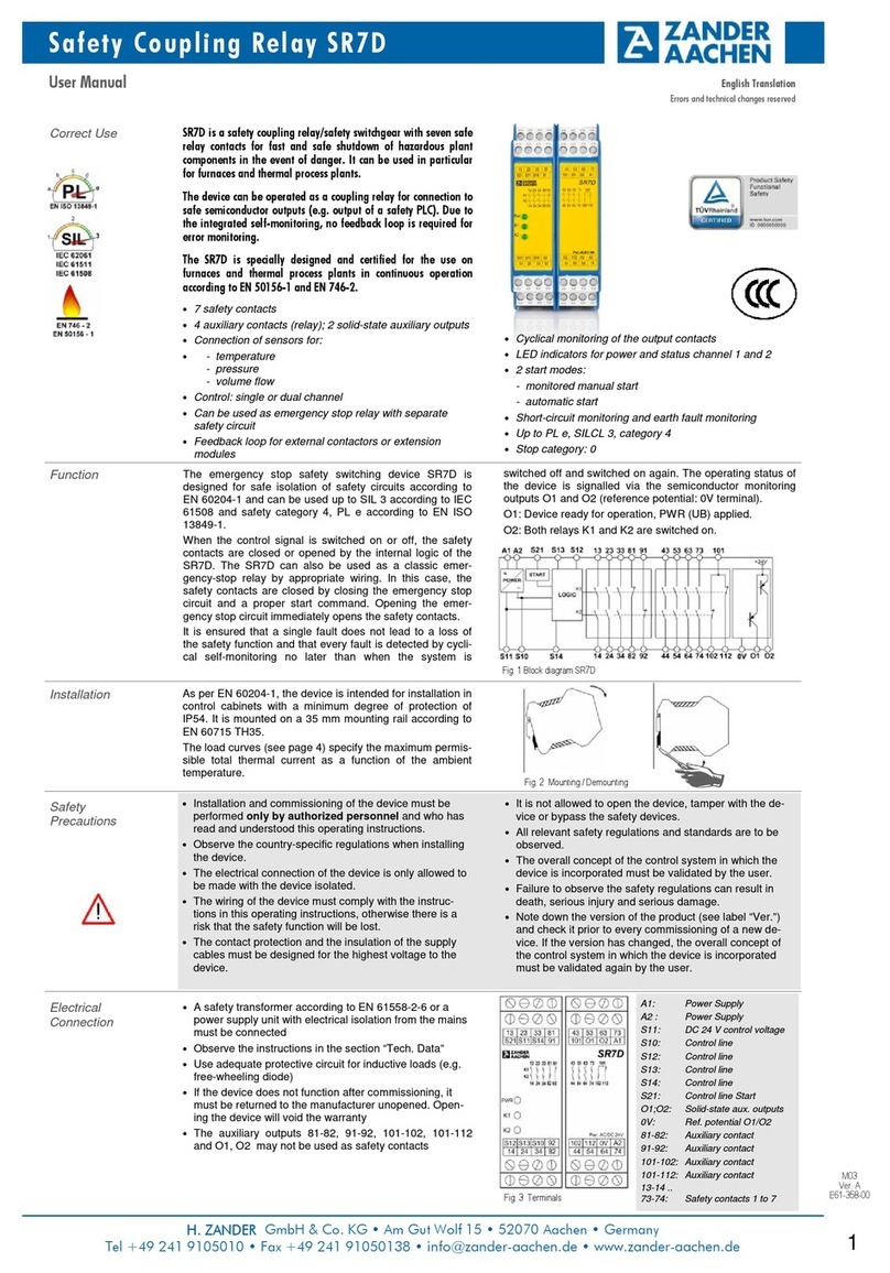
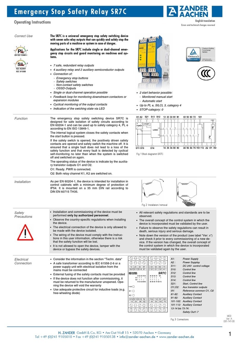
Die HMIs (Human Machine Interfaces) der MVisio Pro Familie dienen zum Steuern, Bedienen und Beobachten von
Maschinenprozessen. Die Geräte sind zum Einsatz in Zone 2 und Zone 22 geeignet. Die Geräte dürfen nur wie in dieser
Anleitung beschrieben verwendet werden. Jede andere Verwendung gilt als nicht bestimmungsgemäß.
Für daraus resultierende Schäden übernimmt H. Zander GmbH & Co. KG keine Haftung.
Allgemeine Sicherheitshinweise
Nur fachlich geschultes Personal darf das Gerät montieren, installieren, betreiben, parametrieren, programmieren und
instand halten.
Die Geräte erfüllen ausschließlich die EMV-Anforderungen für den industriellen Bereich und sind nicht zum Einsatz in
Wohngebieten geeignet.
Das Gerät nur in Übereinstimmung mit den geltenden nationalen und internationalen Bestimmungen, Normen und
Gesetzen einsetzen.
Hinweise zum EX-Schutz
Nationale und internationale Vorschriften für den Explosionsschutz beachten.
Bei Einsatz des Geräts in Ex-Kreisen muss der Anwender über Kenntnisse im Explosionsschutz (EN 60079-14 etc.)
verfügen.
Geräte nur innerhalb der zulässigen Betriebs- und Umgebungsbedingungen (siehe Zulassungsdaten und Auflagen durch
die Ex-Zulassung) einsetzen.
Dieses Gerät, mit Ausnahme des vorderen Displays, ist ein offenes Gerät und muss in einem für die Umgebung geeigneten
Gehäuse installiert werden, so dass der innere Teil des Geräts nur mit Hilfe eines Werkzeugs zugänglich ist.
Geräte in einer zündfähigen Atmosphäre nicht unter Spannung trennen.
Gerät nicht unter Spannung öffnen.
Ethernet-Verbindungen, USB-Geräte und SD-Karten nicht in einer zündfähigen Atmosphäre entfernen.
Batterie nicht in einer zündfähigen Atmosphäre entfernen.
Vor dem Austauschen oder Anschließen von Erweiterungsmodulen Geräte spannungsfrei schalten.
Hinweise zum EX-Schutz (nur USA und Kanada)
Die Geräte sind für den Einsatz in Class1, Division 2, Gruppe A, B, C und D (explosionsgefährdeter Bereich oder nicht-
explosionsgefährdeter Bereich) konzipiert.
Der Anschluss der Spannungsversorgung, der Eingänge und der Ausgänge (I/O) muss gemäß Class I, Division 2 und
gemäß der Vorgaben der jeweils zuständigen Behörde erfolgen. Für die USA gemäß Article 501.10 (B) of the National
Electrical Code, NFPA 70 bzw. für Kanada gemäß Section 18-1J2 of Canadian Electrical Code.
Ausschließlich Komponenten verwenden, die der Class 1, Division 2-Zertifizierung entsprechen.
Auflagen durch die ATEX– und IECEx-Zulassung bei Einsatz in Zone 2 / Zone 22
Gerät nur in Bereichen mit einem Verschmutzungsgrad von maximal 2 gemäß IEC/EN 60664-1 einsetzen.
Bei der Verwendung in Zone 22: Gerät in ein für den Staubbereich zugelassenes Gehäuse der Schutzart IP6x einbauen.
Das Gerät muss in einem Gehäuse mit einer Schutzart mind. IP54 gemäß IEC/EN 60079-15 montiert werden.
Nicht eigensichere Stromkreise nur trennen und verbinden, wenn keine Spannung anliegt.
Funktionen und Betriebsarten
Die Geräte der MVisio-Pro-Familie kombinieren die Funktionen „Steuern, Bedienen und Beobachten“ durch eine
CODESYS-V3-SPS mit integrierter Visualisierung zu einer vollwertigen Steuerungseinheit. Die CODESYS-3-Steuerung der
MVisio-Pro-Geräte verfügt über die Funktionen PROFINET-Controller, EtherNet/IP™-Scanner und Modbus TCP- sowie
Modbus RTU-Master. Darüber hinaus können die Geräte der MVisio-Pro-Familie als Modbus TCP- sowie Modbus RTU-Slave
verwendet werden.
Weitere Funktionen
Ethernet TCP/IP- oder UDP/IP-Kommunikation
OPC-UA-Server und -Client
Serielle Kommunikation über RS232, RS485 und RS422
Produktbeschrei-
bung
5 Zoll 7 Zoll
A147 mm 187 mm
B107 mm 147 mm
C136 mm 176 mm
D96 mm 136 mm
E47 mm 56 mm
F8 mm 8 mm
Kurzbetriebsanleitung Originaldokument
Irrtümer und technische Änderungen vorbehalten
Kurzbetriebsanleitung MVisio HMI Pro
3
H. ZANDER GmbH & Co. KG • Am Gut Wolf 15 • 52070 Aachen • Germany
Tel +49 241 9105010 • Fax +49 241 91050138 • info@zander-aachen.de • www.zander-aachen.de
M06
E61-454-00
Montage
Anschließen
Spannungs-
versorgung
5“-Variante 7“-Variante
A = MVisio Pro, B = Einbauausschnitt
Gerät wie folgt montieren:
Jede der Schrauben anziehen, bis die Ecken des Rahmens
auf dem Panel aufliegen. Das maximale Anzugs-
drehmoment beträgt 1,3 Nm.
Montageort so wählen, dass das Gerät nicht dem
direkten Sonnenlicht ausgesetzt ist.
Lüftungsschlitze im Gerät nicht verdecken.
Anschluss/ Steckplatz Funktion
1USB-Port , V2.0, max 500 mA (nur für Wartung)
2Spannungsversorgung
3Serieller Port
4Ethernet-Port 0 (10/100 Mbit)
5Ethernet-Port 1 (10/100 Mbit)
61 Erweiterungssteckplatz für Plug-In-Module
7SD-Karten-Steckplatz
Gefahr
Explosionsgefahr durch zündfähige Funken
Bei Einsatz in Zone 2 und Zone 22:
Gerät nur montieren, wenn keine explosionsfähige Atmosphäre vorliegt.
Beim Einsatz in Zone 2: Gerät in ein Ex e-Gehäuse nach EN 60079-0 mit einer Schutzart von mind. IP54 montieren.
Beim Einsatz in Zone 22: Gerät in ein für den Staubbereich zugelassenes Gehäuse der Schutzart IP6x einbauen.
Bei der Montage im Gehäuse darauf achten, dass die zulässige Betriebstemperatur des Geräts auch bei ungünstigen
Umgebungsbedingungen nicht überschritten wird.
Hinweis
Geräte der Schutzklasse III nach EN 61140
bzw. Class 2 nach UL-Standard:
Alle Anschlüsse sind SELV-Anschlüsse.
Das Gerät entsprechend der Abbildung anschließen.
Gefahr
Falsche Wahl der Spannungsversorgung
Lebensgefahr durch Überspannung
und Stromschlag
Gerät nur an SELV-Spannungsquellen gemäß
europäischer Norm bzw.
an Class 2-Spannungsquellen gemäß UL-Norm
betreiben.
Gerät entsprechend der Abbildungen an die Versorgungsspannung anschließen.
Kurzbetriebsanleitung Originaldokument
Irrtümer und technische Änderungen vorbehalten
Kurzbetriebsanleitung MVisio HMI Pro

4
H. ZANDER GmbH & Co. KG • Am Gut Wolf 15 • 52070 Aachen • Germany
Tel +49 241 9105010 • Fax +49 241 91050138 • info@zander-aachen.de • www.zander-aachen.de
M06
E61-454-00
Serieller
Anschluss
Pin RS232 RS422/RS485
1RxD CHB-
2TxD CHA-
3CTS CHB+
4RTS CHA+
5+5V VDC output +5V VDC output
6GND GND
7n.c. n.c.
8SHIELD SHIELD
Hinweis:
Bei Nutzung als RS485-Schnittstelle
müssen Pin 1 und 2 sowie
Pin 3 und 4 extern verbunden
werden.
Der minimale Leitungsquerschnitt für den Erdungsanschluss beträgt 1,5 mm².
Gehäuse über die Erdungsschraube auf der Gehäuserückseite erden.
Gerät über Klemme 3 am Spannungsversorgungsanschluss erden.
Gerät erden
In Betrieb
nehmen
Betreiben
Instand halten
Reparieren
Entsorgen
Frontplatte des Geräts vor dem Einschalten mit einem feuchten Tuch reinigen, um jegliche elektrostatische Entladung zu
vermeiden.
Transientenschutz an den Versorgungsanschlüssen vorsehen, der auf maximal 140 % des Spitzenwerts der Nennspannung
eingestellt ist.
Gerät in Zone 2 / Zone 22 betreiben
WARNUNG
Ungeeignete Spannungsversorgung
Verlust der Eignung für Class 1, Division 2
Der Anschluss der Spannungsversorgung, der Eingänge und der Ausgänge (I/O) muss gemäß Class I, Division 2 und ge-
mäß der Vorgaben der jeweils zuständigen Behörde erfolgen. Für die USA gilt die Eignung gemäß Article 501.10 (B) of the
National Electrical Code, NFPA 70 bzw. für Kanada die Eignung gemäß Section 18-1J2 of Canadian Electrical Code.
WARNUNG
Austausch von Komponenten
Eignung für Class 1, Division 2 möglicherweise beeinträchtigt
Beim Austausch von Komponenten darauf achten, dass die Eignung des Geräts für Class1, Division 2 nicht beeinträchtigt
wird.
Nur Komponenten verwenden, die für den Einsatz in Class1, Division 2 geeignet sind.
Ggf. Maßnahmen ergreifen, die die Eignung für Class1, Division 2 wiederherstellen. Die Geräte sind für den Einsatz in
Class1, Division 2, Gruppe A, B, C und D (explosionsgefährdeter Bereich oder nicht-explosionsgefährdeter Bereich) konzi-
piert.
GEFAHR
Explosionsfähige Atmosphäre
Explosionsgefahr durch zündfähige Funken
Bei Einsatz in Zone 2 und Zone 22
Gerät nicht unter Spannung trennen.
Gerät nicht in einer zündfähigen Atmosphäre trennen.
Gerät spannungsfrei schalten, bevor Erweiterungsmodule angeschlossen, entfernt oder ausgetauscht werden.
Batterie nicht in einer zündfähigen Atmosphäre entfernen.
GEFAHR
Explosionsfähige Atmosphäre
Explosion durch zündfähige Funken
Staubschichten auf dem Gerät vermeiden, die die Anhäufung von statischen Ladungen verursachen könnten
die Geräte müssen in regelmäßigen Abständen mit einem feuchten Tuch gereinigt werden.
Das Gerät ist nicht zur Reparatur durch den Benutzer vorgesehen. Sollte das Gerät defekt sein, nehmen Sie es außer Betrieb.
Bei Rücksendung an Firma Zander beachten Sie bitte unsere Rücknahmebedingungen (siehe www.zander-aachen.de).
Das Gerät ist mit einer wieder aufladbaren Lithium-Batterie ausgestattet, die nicht zum Austausch durch den Benutzer
vorgesehen ist.
Zur Entsorgung, die Rückseite des Geräts öffnen und Batterie entfernen.
Das Gerät und die Lithium-Batterie müssen fachgerecht gemäß WEEE-Richtlinie 2012/19/EU entsorgt werden und gehören
nicht in den normalen Hausmüll.
Kurzbetriebsanleitung Originaldokument
Irrtümer und technische Änderungen vorbehalten
Kurzbetriebsanleitung MVisio HMI Pro
5
H. ZANDER GmbH & Co. KG • Am Gut Wolf 15 • 52070 Aachen • Germany
Tel +49 241 9105010 • Fax +49 241 91050138 • info@zander-aachen.de • www.zander-aachen.de
M06
E61-454-00
Technical Data
Connections MVisio HMI Pro (5“-Version) MVisio HMI Pro (7“-Version)
Serial Connection Software configurable
RS232, RS485, RS422
Software configurable
RS232, RS485, RS422
Ethernet Connection 2x RJ45, 10/100 Mbit, separated 3x RJ45, 2x 10/100 Mbit,
1x 10/100/1000 Mbit
USB Connections 1x USB 2.0 2x USB 2.0
Network connection:
Voltage
Current at 24 VDC
10 to 32 VDC; preferred
24 VDC 0.6 A
10 bis 32 VDC; preferred
24 VDC 0.7A
SD-Card slot 1x 1x
Expansion slot Slot for a MVisio I/O Card Slot for a MVisio I/O Card
Product-
identification e.g.:
Imprint Meaning
Type description MVisio HMI Pro
Model 5“ Version
Ident-No. 589103
Productionyear 2020
Serial number X999999
Manufacturer
address H. Zander GmbH & Co. KG
Am Gut Wolf 15, 52070 Aachen
www.zander-aachen.de
EU Declaration of
Conformity
Display MVisio HMI Pro (5“-Version) MVisio HMI Pro (7“-Version)
Touchscreen Technologie Capacitive Capacitive
Display / backlight TFT Color / LED TFT Color / LED
Colors 64 000 64 000
Resolution 800 x 480 800 x 480
Diagonal (Inches) 57
Format 16:9 16:9
Dimmable Yes Yes
Quick Start Guide English Translation
Errors and technical changes reserved
Quick Start Guide MVisio HMI Pro
Versions &
Accessories
Order-no. 589102 MVisio HMI Pro (7“)
Order-no. 589103 MVisio HMI Pro (5“)
Accessories:
Order-no. 589105 MVisio I/O module
Order-no. 589106 Adapter module
More information

6
H. ZANDER GmbH & Co. KG • Am Gut Wolf 15 • 52070 Aachen • Germany
Tel +49 241 9105010 • Fax +49 241 91050138 • info@zander-aachen.de • www.zander-aachen.de
M06
E61-454-00
7“-Version
5“-Version
Dimensions
For your safety Intended use
The HMIs (Human Machine Interfaces) of the MVisio Pro family are used to control, operate and monitor
machine processes. The devices are suitable for use in Zone 2 and Zone 22. The devices may only be used as in this
instructions described. Any other use is considered improper. H. Zander GmbH & Co. KG assumes no liability for any damage
resulting from this.
General Safety Instructions
Only professionally trained personnel may mount, install, operate, parameterize, program and maintain the device.
The devices exclusively meet the EMC requirements for the industrial sector and are not suitable for use in residential
areas.
Only use the device in accordance with the applicable national and international regulations, standards and laws.
Notes on EX protection
Observe national and international regulations for explosion protection.
When using the device in Ex circuits, the user must have knowledge of explosion protection (EN 60079-14 etc.).
Only use the instruments within the permissible operating and ambient conditions (see approval data and conditions of the
Ex approval).
This device, with the exception of the front display, is an open device and must be installed in a housing suitable for the
environment, so that the inner part of the device is only accessible by means of a tool.
Do not disconnect devices under voltage in an ignitable atmosphere.
Do not open the device while it is under voltage.
Do not remove Ethernet connections, USB devices and SD cards in an ignitable atmosphere.
Do not remove the battery in an ignitable atmosphere.
Before exchanging or connecting expansion modules, disconnect devices from the power supply.
Notes on EX protection (USA and Canada only)
The devices are designed for use in Class 1, Division 2, Group A, B, C and D (hazardous or non-hazardous area).
The power supply of the inputs and outputs (I/O) must be connected in accordance with Class I, Division 2 and in
accordance with the specifications of the relevant competent authority. For the USA according to Article 501.10 (B) of the
National Electrical Code, NFPA 70 or for Canada according to Section 18-1J2 of the Canadian Electrical Code.
Only use components that meet Class 1, Division 2 certification.
Conditions imposed by the ATEX and IECEx approval for use in Zone 2 / Zone 22
Only use the device in areas with a pollution degree of maximum 2 according to IEC/EN 60664-1.
For use in Zone 22: Install the device in a housing with protection class IP6x approved for dust areas.
The device must be mounted in a housing with a protection class of at least IP54 according to IEC/EN 60079-15.
Only disconnect and connect non-intrinsically safe circuits when no voltage is applied.
Functions and operating modes
The devices of the MVisio-Pro family combine the functions "control, operation and monitoring" by CODESYS-V3-PLC with
integrated visualisation to a full-fledged control unit. The CODESYS-3 control of the MVisio-Pro devices have the functions
PROFINET controller, EtherNet/IP™ scanner and Modbus TCP and Modbus RTU Master. Furthermore, the devices of the
MVisio-Pro family can be used as Modbus TCP as well as Modbus RTU slave.
Further functions
Ethernet TCP/IP or UDP/IP communication
OPC UA Server and Client
Serial communication via RS232, RS485 and RS422
Product
description
5“ 7“
A147 mm 187 mm
B107 mm 147 mm
C136 mm 176 mm
D96 mm 136 mm
E47 mm 56 mm
F8 mm 8 mm
Quick Start Guide English Translation
Errors and technical changes reserved
Quick Start Guide MVisio HMI Pro

7
H. ZANDER GmbH & Co. KG • Am Gut Wolf 15 • 52070 Aachen • Germany
Tel +49 241 9105010 • Fax +49 241 91050138 • info@zander-aachen.de • www.zander-aachen.de
M06
E61-454-00
Assembly
Connect
Voltage supply
5“-Version 7“-Version
A = MVisio Pro, B = Panel cut-out
Mount the device as follows:
Tighten each of the screws until the corners of the frame
rest on the panel. The maximum tightening torque
is 1.3 Nm.
Select a mounting location so that the device is not exposed
to direct sunlight.
Do not cover the ventilation slits in the device.
Connection/ Slot Function
1USB-Port , V2.0, max 500 mA (for maintenance only)
2Voltage supply
3Serial port
4Ethernet-Port 0 (10/100 Mbit)
5Ethernet-Port 1 (10/100 Mbit)
61 Expansionslot for Plug-In modules
7SD-Card-Slot
Danger
Explosion hazard due to ignitable sparks
For use in Zone 2 and Zone 22:
Only mount the device if no explosive atmosphere is present.
For use in zone 2: Mount the device in an Ex e housing according to EN 60079-0 with a protection class of at least IP54.
For use in zone 22: Install the device in a housing with protection class IP6x approved for dust areas.
When mounting in the housing, make sure that the permissible operating temperature of the device is not exceeded,
even under unfavourable ambient conditions.
Note
Devices of protection class III to
EN 61140 or class 2 to UL standard:
All connections are SELV connections.
Connect the device according to the figure.
Danger
Wrong choice of power supply
Danger to life due to overvoltage
and electric shock
Device only on SELV voltage sources
according to European standard or
at Class 2 voltage sources according to
UL standard.
Connect the device to the supply voltage according to the illustrations.
Quick Start Guide English Translation
Errors and technical changes reserved
Quick Start Guide MVisio HMI Pro

8
H. ZANDER GmbH & Co. KG • Am Gut Wolf 15 • 52070 Aachen • Germany
Tel +49 241 9105010 • Fax +49 241 91050138 • info@zander-aachen.de • www.zander-aachen.de
M06
E61-454-00
Serial
connection
Pin RS232 RS422/RS485
1RxD CHB-
2TxD CHA-
3CTS CHB+
4RTS CHA+
5+5V VDC output +5V VDC output
6GND GND
7n.c. n.c.
8SHIELD SHIELD
Hint:
When used as RS485 interface, pins
1 and 2 as well as pins 3 and 4 must
be connected externally.
The minimum wire cross-section for the earth connection is 1.5 mm².
Ground the housing via the grounding screw on the back of the housing.
Ground the instrument via clamp 3 on the power supply connection.
Ground the
device
Put into operation
Operate
Maintain
Repair
Disposal
Clean the front panel of the unit with a damp cloth before switching on to avoid any electrostatic discharge.
Provide transient protection at the supply terminals, set to a maximum of 140% of the peak value of the rated voltage.
Operate device in Zone 2 / Zone 22
WARNING
Unsuitable voltage supply
Loss of eligibility for Class 1, Division 2
The power supply of the inputs and outputs (I/O) must be connected in accordance with Class I, Division 2 and in accordance
with the specifications of the relevant competent authority. For the USA, suitability according to Article 501.10 (B) of the Nati-
onal Electrical Code, NFPA 70 applies, and for Canada, suitability according to Section 18-1J2 of the Canadian Electrical
Code.
WARNING
Exchange of components
Suitability for Class 1, Division 2 possibly impaired
When replacing components, ensure that the suitability of the device for Class 1, Division 2 is not affected.
Only use components that are suitable for use in Class 1, Division 2.
If necessary, take measures to restore suitability for Class 1, Division 2 The units are designed for use in Class 1, Division 2,
Group A, B, C and D (hazardous or non-hazardous area).
DANGER
Potentially explosive atmosphere
Explosion hazard due to ignitable sparks
For use in Zone 2 and Zone 22
Do not disconnect the device while it is under voltage.
Do not disconnect the device in an ignitable atmosphere.
Disconnect device from power supply before connecting, removing or replacing expansion modules.
Do not remove the battery in an ignitable atmosphere.
DANGER
Potentially explosive atmosphere
Explosion by ignitable sparks
Avoid layers of dust on the device that could cause the accumulation of static charges. The devices must be cleaned at
regular intervals with a damp cloth.
The device is not intended for repair by the user. If the device is defective, take it out of operation. When returning the unit to
Zander, please observe our return conditions.
The device is equipped with a rechargeable lithium battery, which is not intended for replacement by the user.
To dispose of it, open the back of the unit and remove the battery.
The device and the lithium battery must be disposed of properly in accordance with the WEEE Directive 2012/19/EU and
should not be disposed of in normal household waste.
Quick Start Guide English Translation
Errors and technical changes reserved
Quick Start Guide MVisio HMI Pro
Table of contents
Languages:
Other Zander Aachen Relay manuals

Zander Aachen
Zander Aachen MINOS SD1E User manual

Zander Aachen
Zander Aachen SR7C Operation manual

Zander Aachen
Zander Aachen SR4C User manual

Zander Aachen
Zander Aachen SR7C User manual

Zander Aachen
Zander Aachen SPEEDY ZX8T Operation manual

Zander Aachen
Zander Aachen SR7D User manual

Zander Aachen
Zander Aachen SR3C Operation manual

Zander Aachen
Zander Aachen SR3C User manual

Zander Aachen
Zander Aachen ZX09 Series User manual

Zander Aachen
Zander Aachen SR3D Operation manual