Eton America ROVER GT User manual

ETON America
ROVER GT
SERVICE MANUAL
ROVER GT (UK2)
ROVER GT 7 / 2007
www.Get2itParts.com
www.Get2itParts.com
www.Get2itParts.com

1
Table of Contents
1. INFORMATION...................................................................................................................................... 3
1.1 Safety .................................................................................................................................................3
1.2 Notes..................................................................................................................................................3
1.3 Specifications.....................................................................................................................................4
1.4 VIN & Engine Number......................................................................................................................6
1.5 Standard Torque Values.....................................................................................................................7
2. MAINTENANCE..................................................................................................................................... 8
2.1 Maintenance Schedule.......................................................................................................................8
2.2 Maintenance Record ..........................................................................................................................8
2.3 Fuel Lines & Filter.............................................................................................................................9
2.4 Throttle Operation..............................................................................................................................9
2.5 Throttle Cable Adjustment.................................................................................................................9
2.6 Air Cleaner.......................................................................................................................................10
2.7 Spark Plug........................................................................................................................................10
2.8 Idle Speed.........................................................................................................................................11
2.9 Drive Chain......................................................................................................................................11
2.10 Braking Systems ............................................................................................................................12
2.11 Wheels & Tires..............................................................................................................................13
2.12 Steering System .............................................................................................................................13
2.13 Toe-In.............................................................................................................................................13
2.14 Gear Oil..........................................................................................................................................14
3. ENGINE REMOVAL AND INSTALLATION........................................................................................ 15
3.1 Service Information .........................................................................................................................15
3.2 Engine Removal...............................................................................................................................15
3.3 Engine Installation...........................................................................................................................15
4. FUEL AND LUBRICATION SYSTEMS................................................................................................ 17
4.1 Trouble Shooting .............................................................................................................................17
4.2 Fuel Tank.........................................................................................................................................18
4.3 Carburetor........................................................................................................................................18
4.4 Engine Oil Level & Changing .........................................................................................................20
4.5 Oil Pump removal / Installation.......................................................................................................22
5. ENGINE COMBUSTION SYSTEM...................................................................................................... 26
5.1 Service & General Information........................................................................................................26
5.2 Trouble Shooting .............................................................................................................................26
5.2 Trouble Shooting .............................................................................................................................27
5.3 Top End Removal............................................................................................................................28
5.4 Cylinder Head Removal...................................................................................................................30
5.5 Cylinder Head Assembly.................................................................................................................33
6. CYLINDER & PISTON......................................................................................................................... 36
6.1 Service Information .........................................................................................................................36
6.2 Trouble Shooting .............................................................................................................................36
6.3 Cylinder & Piston Removal.............................................................................................................37
6.4 Piston Installation.............................................................................................................................41
7. TRANSMISSION SYSTEM.................................................................................................................. 44
7.1 Service Information .........................................................................................................................44
7.2 Shift Mechanism C.D.I.....................................................................................................................45
7.3 Automatic Variable Speed Transmission (C.V.T.)..........................................................................45
7.4 C.V.T. Belt.......................................................................................................................................46
www.Get2itParts.com
www.Get2itParts.com
www.Get2itParts.com

2
7.5 Electrical Starter Mechanisim..........................................................................................................46
7.7 C.V.T. Reassembly..........................................................................................................................50
8A. TRANSMISSION GEAR SET............................................................................................................ 52
8A.1 Service Information.......................................................................................................................52
8A.2 Trouble Shooting...........................................................................................................................53
8A.3 Gear Removal ...............................................................................................................................53
8A.4 Gear Set and Bearing Inspection...................................................................................................54
8A.5 Gear Set Installation......................................................................................................................55
8B. SHIFTING GEAR BOX...................................................................................................................... 56
8B.1 Service Information.......................................................................................................................56
8B.2 Trouble Shooting...........................................................................................................................57
8B.3 Transmission Assembly Drawing.................................................................................................58
8B.4 Shift Mechanism ...........................................................................................................................59
8B.5 Gear Box Assembly ......................................................................................................................60
9. STEERING SYSTEM............................................................................................................................ 61
9.1 Steering System Drawing..................................................................................................................61
9.2 Trouble Shooting...............................................................................................................................61
9.3 Steering Wheel Removal...................................................................................................................62
9.4 Steering System Removal......................................................................................................................62
10. WHEEL AND BRAKE SYSTEM......................................................................................................... 67
10.1 Wheel and Brake System Drawings ..............................................................................................67
10.2 Troubleshooting.............................................................................................................................68
10.3 Wheel Removal & Installation.......................................................................................................68
10.4 Drive Mechanism & Rear Brake Removal....................................................................................69
10.5 Front Hydraulic Disc Brake System..............................................................................................72
11. BODY COVERS AND EXHAUST SYSTEM....................................................................................... 77
11.1 Body Cover Drawings....................................................................................................................77
11.2 Cage & Body Cover Removal .......................................................................................................77
11.3 Exhaust System Drawing...............................................................................................................79
11.4 Exhaust System Removal ..............................................................................................................80
11.5 Servicing the Spark Arrestor..........................................................................................................80
12. ELECTRICAL SYSTEM...................................................................................................................... 82
12.1 Trouble Shooting ...........................................................................................................................82
12.2 Ignition Coil...................................................................................................................................84
12.3 Ignition Timing..............................................................................................................................84
12.4 Battery Inspection and Maintenance..............................................................................................84
12.5 Wiring Diagram.............................................................................................................................87
13. TROUBLESHOOTING................................................................................................. 88
13.1 Engine Does Not Start ...................................................................................................................88
13.2 Poor Performance at Low Idle.......................................................................................................89
13.3 Poor Performance at High Speed...................................................................................................89
13.4 Loss of Power ................................................................................................................................90
13.5 Poor Handling................................................................................................................................91
www.Get2itParts.com
www.Get2itParts.com
www.Get2itParts.com
3
1. INFORMATION
1.1 Safety
Gasoline is extremely flammable and is explosive under certain conditions. Do not smoke or allow sparks or
flames in your work area.
Never run the engine in a closed area. The exhaust contains poisonous carbon monoxide gas that may
cause loss of consciousness and lead to death.
The battery electrolyte contains sulfuric acid. Protect your eyes, skin and clothing. If you contact it, flush
thoroughly with water and call a doctor if electrolyte gets in your eyes.
Engine and exhaust pipe become very hot and will remain hot for one hour after the engine is shut off.
Do not perform service on parts that are hot.
Used engine oil and gear oil may cause personal damage after repeated or long exposure to skin.
Keep out of reach of children. Recycle or dispose of engine and gear oil properly at a proper facility.
1.2 Notes
All information, illustrations, directions and specifications included in this publication are base on the latest
product information available at the time of approval for printing.
These symbols will appear throughout the manual to indicate important information or tasks.
CAUTION – Safety notification. Proceed carefully.
ADJUSTMENTS – Requires inspection, adjustment, or torque.
FLUIDS – Lubrication or check and replace fluids.
MULTIMETER – Diagnostics and electrical testing.
MEASUREMENT – Gap and size measurements.
SPECIAL TOOL – Uncommon tools may be required.
GENERAL MAINTENCE PART – These parts may need to be replaced often. Part numbers will be
provided when applicable.
ETON America, LLC reserves the right to make changes at any time without notice and without incurring
any obligation whatever. No part of this publication may be reproduced without written permission.
www.Get2itParts.com
www.Get2itParts.com
www.Get2itParts.com

4
1.3 Specifications
Component
Rover GT
(UK2)
Engine
Type Four cycle liquid cooled
Displacement 88.4cc
Bore / Stroke φ47.0 * 51mm
Compression Ratio /
Pressure 10.2 : 1
Torque / BHP 6.5hp @ 6500rpm / 48BHP
Starting Electrical
Transmission
Type Automatic (C.V.T. V-Belt)
Chassis
Overall Length 2110mm / 83.0"
Overall Width 1000mm / 39.4"
Overall Height 1110mm / 43.7"
Wheel Base 1375mm / 54.1"
Seat Height 710mm / 28.0"
Dry Weight 185kg / 408lbs
Suspension
Front Swing A-arm
Dual Adjustable Shocks
Rear Swing Arm
Adjustable Shock
Brakes
Front Dual Hydraulic Disc
Rear Hydraulic Disc
Tires
Front 18/7-10
Rear 18/8-10
Tire
Pressure
Front Min 3.2psi / 0.23kg/cm2
Max 4.0psi / 0.28kg/cm2
Rear Min 3.2psi / 0.23kg/cm2
Max 4.0psi / 0.28kg/cm2
Wheels
Bolt Pattern 4 x 110mm (P.C.D)
Carburetor
Make/Size TK SVR 22mm (Manual
Choke)
Main Jet 0.95mm
Pilot Jet 0.32mm
Air Mixture Adjustment Back out 1 1/2 – 1 3/4 turns
Idle Speed Idle 1700 - 1900rpm
Sprockets
Specifications are subject to change without notice.
Continued on next page.
www.Get2itParts.com
www.Get2itParts.com
www.Get2itParts.com

5
Front 520x12t
Rear 520x32t
Chain #520
Battery Size
Jell Acid (Maintenance
Free) 12V-4AH/5AH - GTX5L
Fluids
Fuel Type Unleaded Gasoline 92 octane
Volume 11 liters / 2.9gal
Engine Oil Type SAE 20W - 40
Volume 0.9 liters / 0.23gal
Transmission Type SAE 80/90 weight
Volume 300cc / 10.2oz
Spark Plug
NGK CR7HSA/NGK
Champion Z9Y (Not recommended)
Electrode
Gap 0.6-0.7mm / 0.023"
Specifications are subject to change without notice.
www.Get2itParts.com
www.Get2itParts.com
www.Get2itParts.com

6
1.4 VIN & Engine Number
The unit’s serial numbers are available directly on the unit. See the pictures below.
The frame VIN number is stamped on the right side of the frame near the front right wheel.
The engine VIN number is stamped on the left side of the crankcase.
Frame Number
Engine Number
www.Get2itParts.com
www.Get2itParts.com
www.Get2itParts.com
7
1.5 Standard Torque Values
NOTE: Maximum metric torque value is shown. Do not exceed maximum torque value.
ENGINE
Cylinder head nut 25 N/m (13.3 – 18.4 lbf-ft)
Spark plug 12 N/m (5.2 - 8.9 lbf-ft)
Cylinder head bolt 30 N/m (14.8 - 22.1 lbf-ft)
Alternator bolt 12 N/m (5.9 - 8.9 lbf-ft)
FRAME
Handlebar upper holder bolt 24-30 N/m (17.7-22.1 lbf-ft)
Steering shaft nut 50-60 N/m (36.9-44.3 lbf-ft)
Steering shaft bushing holder nut 24-30 N/m (17.7-22.1 lbf-ft)
Wheel rim bolt 18-25 N/m (13.3-18.4 lbf-ft)
Tie rod lock nut 35-43 N/m (25.8-31.7 lbf-ft)
King pin nut 30-40 N/m (22.1-29.5 lbf-ft)
Handlebar lower holder nut 40-48 N/m (29.5-35.4 lbf-ft)
Front wheel bolt 24-30 N/m (17.7-22.1 lbf-ft)
Front axle nut 30-35 N/m (22.1-25.8 lbf-ft)
Front brake arm nut 4-7 N/m (3.0- 5.2 lbf-ft)
Rear brake arm nut 7-12 N/m (5.2- 8.9 lbf-ft)
Rear axle nut 60-80 N/m (44.3-59.0 lbf-ft)
Rear wheel bolt 24-30 N/m (17.7-22.1 lbf-ft)
Exhaust muffler mounting bolt 30-35 N/m (22.1-25.8 lbf-ft)
Engine hanger bolt 24-30 N/m (17.7-22.1 lbf-ft)
www.Get2itParts.com
www.Get2itParts.com
www.Get2itParts.com

8
2. MAINTENANCE
2.1 Maintenance Schedule
The maintenance internals in the follow table are based upon average riding conditions. Riding in unusually dusty
areas requires more frequent servicing. This table applies to units covered by this service manual. E-TON
recommends that all maintenance and inspections be performed ONLY by a qualified and fully trained technician.
INITIAL
SERVICE
REGULAR SERVICE
EVERY YEAR
(First week) (Every 30 operating days)
Fuel Line I
Throttle Operation I I I
Air Filter system & Element I C R
Spark Plug I R
Carburetor Idle Speed I I I
Drive Chain I, L I, L I
Brake Shoe Wear I I I
Brake System I I I
Nut, Bolt, Fastener I I I
Wheels & Wheel Nuts I I I
Steering System I I
Suspension System I I
C.V.T. Air Filter C R
Waste Gas Recovery Valve I R
Intake & Exhaust Valve Adj. I
Gear & Engine Oil I R
Note –
I: Inspect and Clean, Adjust, Lubricate, or Replace (if necessary)
C: Clean
L: Lubricate
R: Replace
2.2 Maintenance Record
Maintenance Performed Date Performed By
www.Get2itParts.com
www.Get2itParts.com
www.Get2itParts.com
Maintenance Schedule
Four Stroke Vehicles
WP-0027
Scheduled
Maintenance
300KM Every1000KM Every3000KM Every6000KM Every12000KM
200Miles600Miles2000Miles3700Miles7500Miles
NEW 1Month3Months 6Months 1Year
1Aircleanerelement I*C* R(paper) R(sponge)
2Aircleaner I
3Oilfilter(Screen) C C
4Engineoil Change I Change
5Tire,pressure I I
6Battery I I
7Sparkplug I I R
8Carburetor(idlespeed) I I
9Steeringbearingandhandles I I
10
Checktransmissionforleak‐
age I I
11Checkcrankcaseforleakage I I
12Transmissionoil Change Change
13Drivebelt/roller I R
14Fueltankswitchandlines I I
15
Throttlevalveoperationand
cable I I
16Engineboltsandnuts I I
17
Cylinderhead,cylinder,and
piston I
18
Exhaustsystem/cleaning
carbon I
19CamChain/ignitiontime I I
20Valveclearance I I I I I
21Shockabsorbers I I
22Front/Rearsuspension I I
23Main/Sidestands I I/L
24Crankcase(PCV)Valve I I
25
Brakemechanism/brakelin‐
ing(pad) I I
26
TightenallBolts/Nuts&Fas‐
teners
I I
*=Cleanorreplacetheaircleanerelementmoreoftenwhenthevehicleisoperatedondusty
#=Maintenanceshouldbeperformedmoreoftenifthevehicleisfrequentlyoperatedathigh
speedforprolongedtimeandafterthevehiclehasaccumulated50,000miles.
roadsorinaheavilypollutedenvironment.
Code:
I=Inspection,clean,andadjust
R=Replace
C=Clean(replacedifnecessary)
L=Lubricate
www.Get2itParts.com
www.Get2itParts.com
www.Get2itParts.com
9
2.3 Fuel Lines & Filter
Inspect the fuel lines for deterioration, damage, or leakage, and
replace if necessary.
Check the fuel filter for accumulated dirt and debris. Replace as
needed. Filter replacement is also recommended at the
beginning of each riding season.
Filter assembly: Part # 812555
Filter element: Part # 800002
2.4 Throttle Operation
•Inspect the throttle for smooth operation in all open and
closed positions. Ensure that there is no wear, damage, or
kinking in the throttle cable; replace it if necessary.
•To lubricate cable, disconnect the throttle cable at the upper
end. Lubricate the cable with commercially available lubricant to
prevent premature wear and binding of the cable in the case.
•To replace a damaged or worn cable, order part # 812469.
2.5 Throttle Cable Adjustment
•The cable should be adjusted to allow for 1/8" free travel
before the throttle engages the carburetor throttle slide.
•To adjust the cable's free travel, loosen the locking nut of
the cable adjuster, and turn the adjuster wheel until there is
1/8" free travel in the lever.
•Tighten the locking nut to secure the adjusting ring.
www.Get2itParts.com
www.Get2itParts.com
www.Get2itParts.com

10
2.6 Air Cleaner
•Unscrew the air cleaner cover screws.
•Pull out the air filter element from the air cleaner case.
Wash the element in non-flammable solvent and squeeze
out the solvent thoroughly.
•Let it dry.
•Soak the filter element in gear oil, and then squeeze out the
excess oil.
•Install the element into air cleaner carefully.
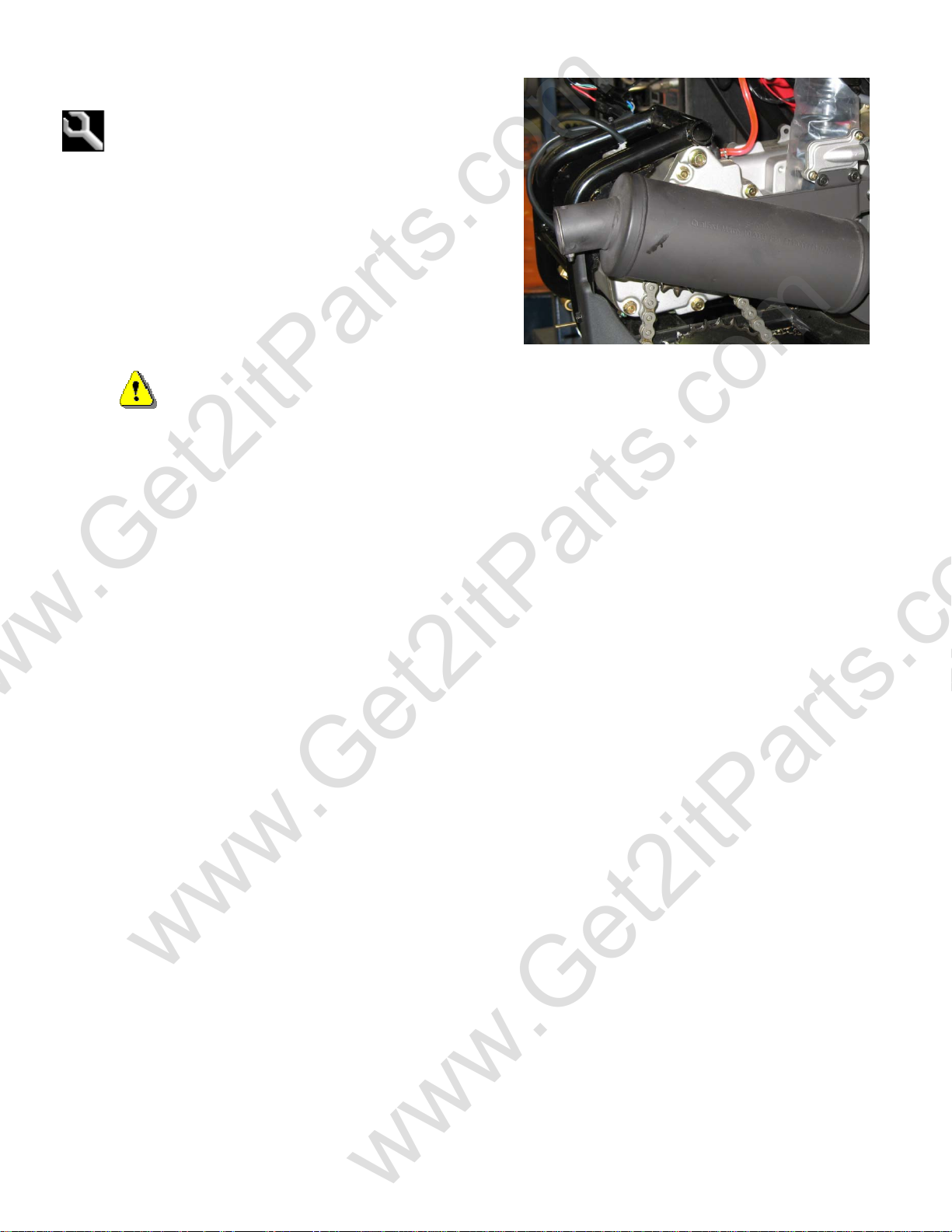
2.7 Spark Plug
To change the spark plug, do the following:
1. Stop the engine and wait for it to cool, 30-60 min. (Never work on a hot engine. A hot engine and exhaust can present
a fire and burning hazard.)
2. Locate the spark plug at the front of the engine.
3. Remove the Spark plug lead wire by gently pulling on the plug wires boot. (Do not pull on the wire itself as this could
cause damage to the wire).
4. Remove the old spark plug using the supplied plug wrench and screwdriver
by turning the plug counter clockwise.
5. Set the electrode gap on the new plug to 0.6m-0.7mm / 0.023” using a feeler
gauge.
6. Insert the new plug by hand and tighten finger tight by turning the plug in a
clockwise direction. Use caution not to cross thread the plug in the head.
7. Use the plug wrench to tighten the plug another ¼ to ½ turn. Caution:over
tightening the plug can cause the thread in the engine head to be stripped; under
tightening the plug can cause compression loss and possible cylinder head
failure.
8. Reinstall the plug wire by pressing the wire boot over the plug until it is
completely seated on the spark plug.
ETON recommends that you replace your spark plug at the beginning of
each riding season.
Note: ETON recommends the use of NGK CR7HSA
Plug MFG MFG Num Plug Gap Part
NGK CR7HSA 0.6-0.7mm / 0.023” # 811777
www.Get2itParts.com
www.Get2itParts.com
www.Get2itParts.com

11
2.8 Idle Speed
Air/Fuel Ratio adjusting procedure:
Step 1: Air adjusting screw.
Turn adjusting screw all the way in then back off
¾ to 1¼ turn on 70cc engine.
1 to 1½ turns on 90cc engine.
Step 2: Adjust idle RPM. (Warm Engine)
Connect an RPM gauge. Turn the adjustment screw in or out to
adjust the engine idle speed to between 1700—1900 RPM.
Turning the idle adjustment screw clockwise will raise the RPM;
turning it counterclockwise will lower the RPM.
Idle Speed: 1800 ± 100RPM
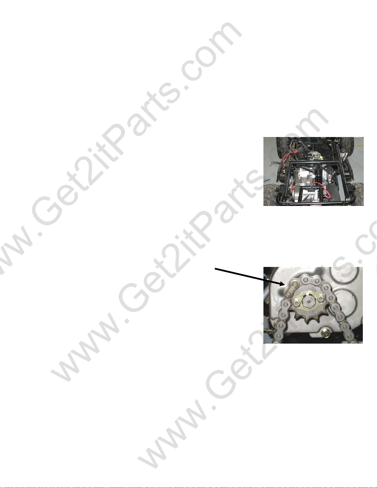
2.9 Drive Chain
Inspect the chain slack. The standard is 10-25mm or 0.394-0.984
in.
The drive chain will stretch with use and will require periodic
adjustments. To check the chain tension, remove the chain guard
and measure the slack. The amount of slack in the chain should
not exceed 10-25mm (0.394-0.984 in).
Inspect the drive and axle sprockets for damaged or broken
teeth. Replace as needed. Inspect the chain links for damaged,
worn or loose rivets. Repair or replace as needed.
Chain Slack Adjustment:
Loosen the axle position lock bolts slightly and turn the chain
adjuster nut to take up the excess slack in the chain. Once the
chain has been adjusted to the proper tension retighten the
axle position locking bolt.
The chain should be kept well lubricated to prevent excess
wear and premature failure. We recommend that you lubricate
the chain every 20 hours of operation, or more frequently if
needed, with a high quality chain lubricant.
Air mixture adjusting screw
Chain adjusters
www.Get2itParts.com
www.Get2itParts.com
www.Get2itParts.com

12
When the drive chain becomes very dirty, it should be
removed, cleaned, and lubricated. Use commercial chain
lubricant to lubricate the drive chain.
Clean the drive chain with kerosene and wipe it dry. Inspect the
drive chain for worn or damaged links and rivets. Replace the chain
if it is worn excessively or damaged.
Inspect the sprocket teeth. If there is excessive wear or
damage, replace the sprocket.
Engine Sprocket - Part #: 812478
Drive Axle Sprocket - Part #: 812597 (520x32t)
2.10 Braking Systems
Inspect the front parking brake lever (the right hand lever) and cable
for excessive wear or other damage. Replace or repair if
necessary. Measure the slack of the brake lever at the end of
the brake lever. The standard of slack is 15-25 mm (0.591-
0.984 in).
Adjuster
www.Get2itParts.com
www.Get2itParts.com
www.Get2itParts.com
13
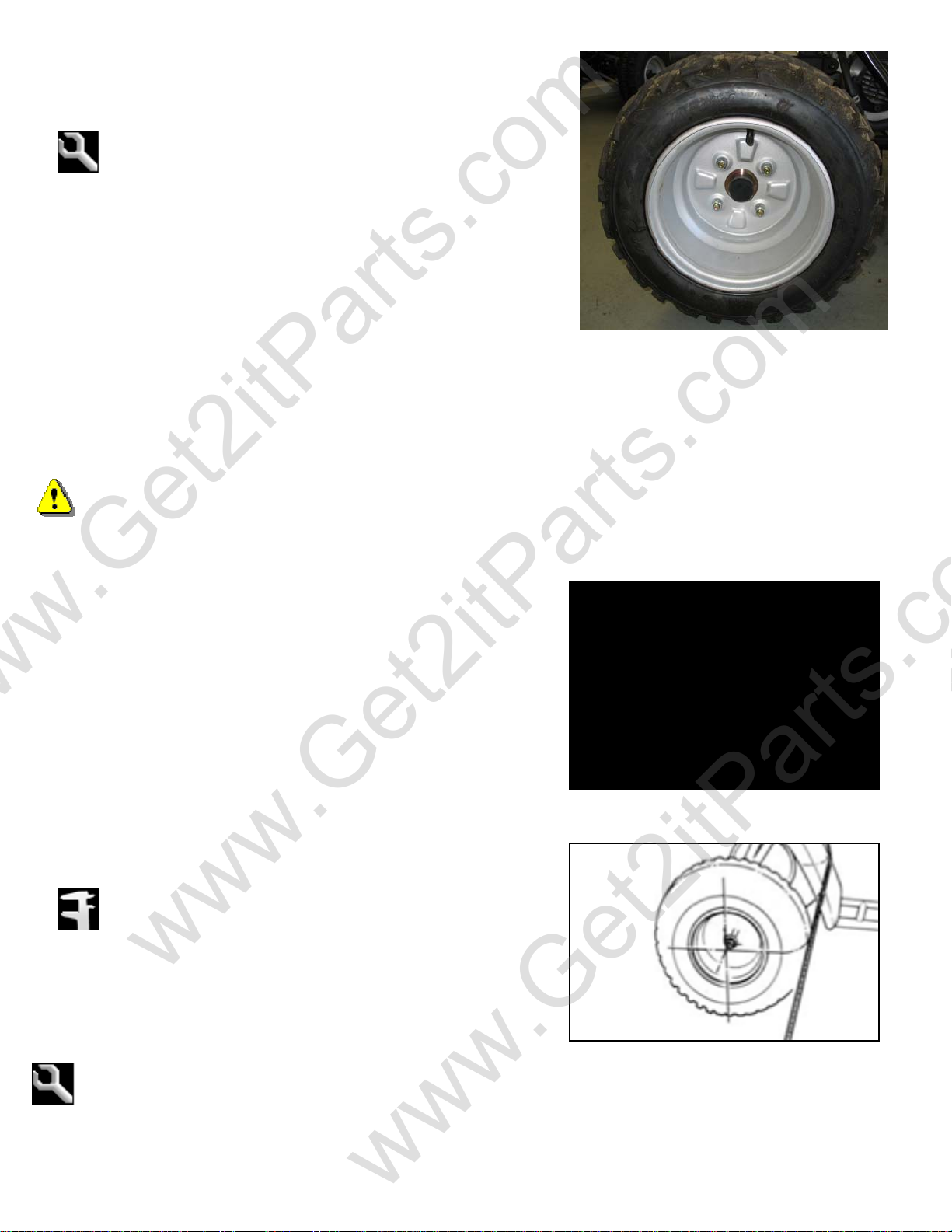
2.11 Wheels & Tires
•Inspect the tire surfaces for cuts, nails, or other sharp
objects.
•Check the tire surfaces at cold tire condition. The
standard tire pressure is 2.2±0.3 psi. (0.15
kg/cm2)
2.12 Steering System
Check the slack of the steering shaft with the front wheels facing
straight ahead. When there is excessive slack, inspect the tie-rod,
kingpin bushing and ball joint.
NOTE – This procedure should be performed on all units
during setup.
2.13 Toe-In
•Park the vehicle on level ground and leave the front wheels
facing straight ahead.
•Mark the centers of the tires to indicate the axle center
height.
•Measure the distance between the marks.
•Carefully move the vehicle back, and rotate the wheels
180°, so the marks on the tires are aligned with the axle
center height on the other side.
•Measure the distance between the marks. Calculate
the difference in the front and rear measurements.
•Toe-in: 5±10mm (0.197±0.394 in)
If the toe-in is out of standard, adjust it by changing the length
of the tie-rods equally. Loosen the locking nuts and turn the
tie-rod while holding the ball joint.
Tighten the lock nuts.
Torque: 35-43 N/m (2.40-2.95 lb/ft)
www.Get2itParts.com
www.Get2itParts.com
www.Get2itParts.com

14
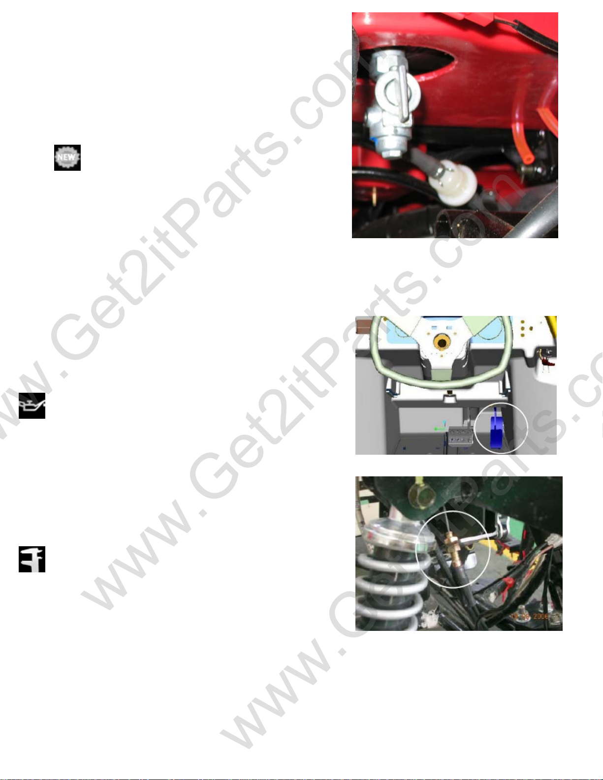
2.14 Gear Oil
Gear oil needs to be changed every year.
1. Place an oil catch pan under the unit directly below the
transmission box.
2. Remove the transmission box drain plug located on the
bottom of the transmission box on the underside
of the unit.
3. Remove the transmission box fill hole plug locate on top of
the transmission box near the oil tank bracket on the left hand
side of the unit.
4. Allow the oil to drain completely (15-30 min).
5. Reinstall the drain plug and tighten. Torque to 7-10lbf-ft
6. Fill the transmission box with of SAE 80-90 gear oil
• Capacity = 300cc / 10.2oz
7. Reinstall the fill hole plug and finger tighten
8. Dispose of used oil at a proper recycling station as required by
law.
Bottom of engine
Drain Bolt
Front of engine
Top of engine
Fill Plug
Front of engine
www.Get2itParts.com
www.Get2itParts.com
www.Get2itParts.com
15
3. ENGINE REMOVAL AND INSTALLATION
3.1 Service Information
NOTE: The engine should only be removed when repair conditions warrant its removal. Engine removal is a
complex task that should be performed only by a qualified technician or mechanic.
3.2 Engine Removal
1. Remove the seat, side panels and fenders. (See Section 11)
2. Disconnect the spark plug cap from spark plug.
3. Remove the exhaust muffler assembly.
4. Disconnect the throttle cable from the carburetor by removing the two
screws on top of the carburetor.
5. Disconnect the wire connections:
a. Carburetor auto-choke (If installed)
b. Carburetor manual choke cable (If installed)
c. Starter motor
d. A/C generator
e. C.D.I. Leads (Label before disconnecting)
f. Disconnect the shifting motor
g. Label & disconnect the shift sensor leads
h. Disconnect the engine ground wire on the (LH) side of the
engine
6. Disconnect the fuel line from the carburetor.
7. Remove the drive chain cover.
8. Remove the drive chain retaining clip and master link.
9. Remove the drive chain.
10. Remove the three engine hanger nuts and bolts.
11. Carefully remove the engine from the right side of frame.
3.3 Engine Installation
www.Get2itParts.com
www.Get2itParts.com
www.Get2itParts.com
16
Engine installation is basically removal in reverse.
1. Replace the engine in the frame from the right side.
2. Reinstall the engine hanger bolts and torque to 24-
30 N/m (1.64-2.06 lb/ft).
3. Reinstall the drive chain, and connect with the
master link and retaining clip.
4. Reinstall the chain guard.
5. Reconnect the wire connections:
1. Carburetor auto-choke (If installed)
2. Carburetor manual choke cable (If installed)
3. Starter motor
4. A/C generator
5. Reconnect C.D.I. leads
6. Reconnect the engine ground wire on the
(LH) side of the engine
7. Reconnect the shift motor
8. Reconnect the shift sensor leads
Note: Use care when rerouting the cables and wires so as not to pinch or bend them.
6. Reconnect the throttle cable.
7. Reinstall the exhaust muffler assembly.
Note: Replacement of the exhaust gasket with a new gasket is recommended.
8. Reconnect the fuel line.
9. Replace the spark plug cap.
10. Test-start the engine.
11. Test the shifting function.
12. Reinstall fenders, side panels, and seat.
www.Get2itParts.com
www.Get2itParts.com
www.Get2itParts.com

17
4. FUEL AND LUBRICATION
SYSTEMS
4.1 Trouble Shooting
•No fuel in tank
•No fuel to cylinder
•Too much fuel going into cylinder
•No spark at plug
•Air cleaner clogged
•Improper adjustment of the idle speed screw
•Ignition malfunction
•Bad fuel/air mixture ratio
•Air filter dirty
•Intake leaks
•Fuel tank cap breather clogged
•Main jet or pilot jet clogged
•Fuel filter clogged
•Fuel flows restricted
•Float level in carburetor set too low
•Lean mixture/rich mixture
•Faulty float needle valve
•Float level set too high
•Carburetor air duct is clogged
Engine does not start.
Engine idles roughly, stalls, or runs poorly.
www.Get2itParts.com
www.Get2itParts.com
www.Get2itParts.com
18
4.2 Fuel Tank
REMOVAL
•Remove the fuel tank cap and rear bed assembly.
•Disconnect the fuel line from the carburetor.
•Unscrew the fuel tank mounting bolts.
Warning: Gasoline is highly flammable
Note: Keep gasoline away from flames or sparks.
Wipe up spilled gasoline at once.
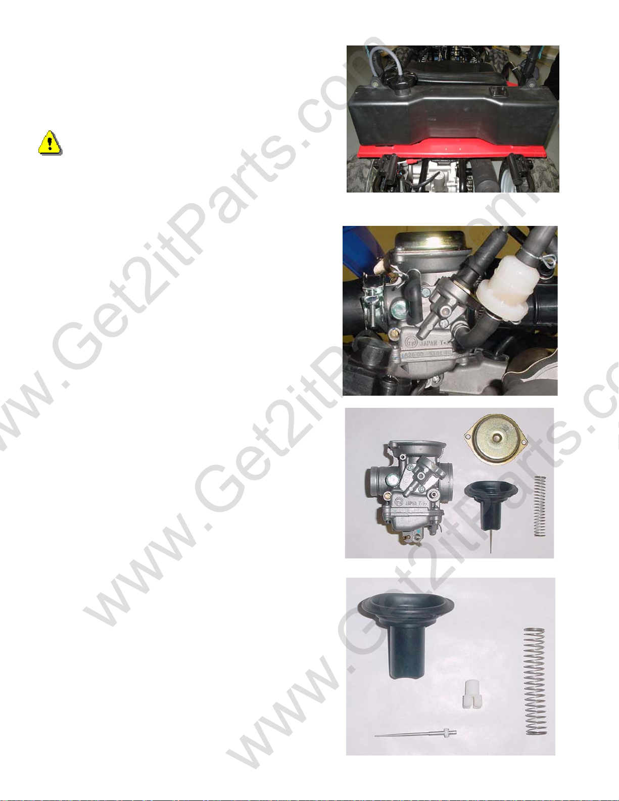
4.3 Carburetor
REMOVAL
Note: Turn fuel petcock to “off” position
•Remove the air filter assembly.
•Disconnect the fuel line and choke cable or lead wire.
Unscrew the intake pipe mounting bolts at the
carburetor
•Remove the carburetor
DISASSEMBLY
•Remove the carburetor cap.
•Remove the throttle cable from the throttle valve while
depressing the throttle valve spring.
•Remove the needle clip retainer, the jet needle, and
needle clip.
•Inspect the throttle valve and jet needle surface for
wear, scratches or dirt.
www.Get2itParts.com
www.Get2itParts.com
www.Get2itParts.com
This manual suits for next models
1
Table of contents
Popular Utility Vehicle manuals by other brands

Wilson Electronics
Wilson Electronics 082614 Assembly instructions

Montracon
Montracon MT45 Operator's handbook

Club Car
Club Car Turf 1 2006 owner's manual

Polaris
Polaris RANGER XP 900 2013 owner's manual
Textron Specialized Vehicles
Textron Specialized Vehicles TRACKER LX6 EFI Repair and service manual

Bailey
Bailey Pursuit owner's manual


