7 8
MECHANICAL INSTALLATION MECHANICAL INSTALLATION
ELECTRICAL INSTALLATION
Do not use your automobile until all components of the loudspeaker system have
been secured to the interior framework. Failure to do so may turn a component into
a dangerous, flying projectile during a sudden stop or accident.
Do not drill or drive screws through any vehicle interior or carpeted floor before
inspecting the underside for potential punctures to control lines or cables. Be sure
to avoid all fuel lines, brake lines, electrical cables or oil lines when planning the
installation.
Before beginning installation of the loudspeaker system remove the minus
connector from the automobile battery in order to avoid possible short circuits.
Caution: Use care when removing interior trim panels. Car manufacturers use a
variety of fastening devices that can be damaged in the disassembly process.
Choosing a Location
For ease of installation use original factory speaker locations. Using these positions will
save considerable installation time and provide the best optical integration. Avoid installing
speakers behind thick stock fabric or cloth. This could - especially in the case of tweeters -
restrict output and reduce sound volume.
Installation too close to reflective surfaces can negatively affect stereo imaging. The
distance between each mid/woofer and tweeter pair should not exceed 60 cm. We suggest
first mounting the mid/woofer and attaching the cables. Then you can determine the
optimum tweeter location by auditioning the tweeters at several positions in your
automobile before permanent installation.
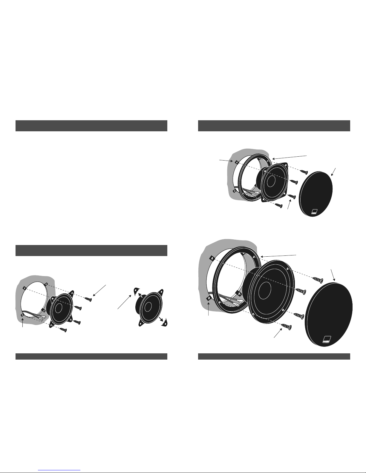
Installation of Mid/Woofer
If it is not possible to install the loudspeaker in the original factory speaker location, the
most used position is the door panel.
1. After choosing a location, carefully remove the trim panels. Be sure that sufficient
mounting depth is available and that no moveable mechanical parts (window, window
regulator handle) are restricted in their functionality.
3. If you plan to use grilles or panels in front of the loudspeaker, ensure that sufficient space
is available for the path of the loudspeaker cone. Should the distance not be sufficient,
the cone could vibrate against the grille or panel thus damaging the loudspeaker.
2. Use the enclosed drilling template to cut a suitable hole in the trim panel and, if
necessary, in the sheet metal behind. Drill holes for the fastening screws. Mount the
parts as shown in figure 1.
Attention: If sheet metal must be cut or removed contact your authorized car
dealer for professional advice. By damage to supporting body structures the
safety certificate may be withdrawn.
Installing the Tweeters
The tweeters can be flush- and surface-mounted. Consider that repeated opening and
closing of the car door can result in loosening of the tweeter fastening devices, when the
loudspeaker is mounted in the door panel.
1. Flush mounting: Use the enclosed drilling template to cut a suitable hole. Lay the
leading connector cable and mount the parts as shown in figure 2.
The specialty of the ETON mounting cabinet is that the tweeter element can be turned
and swiveled to achieve the optimum hearing path to your sitting position. See figure 3.
Disassambly: To remove the tweeter element from the mounting cabinet turn the
element to its middle position and place two round metal rods with a diameter of 1,0 mm
to the limit in both openings right and left of the tweeter element. By swiveling of the
tweeter you can now move it upwards and remove it.
2. Surface mounting: Drill two holes for the fastening screws and one hole for the leading
connector cable using the mounting cabinet as a guide. Consider the preferred incline of
the mounting cabinet. Mount the parts as shown in figure 4.
Caution: Use care when removing interior trim panels. Car manufacturers use a
variety of fastening devices that can be damaged in the disassembly process.
Whenever you run wires through sheet metal, use tape or grommets to properly insulate
the metal edges from cable jackets. This technique prevents chafing and possible short
circuits that could damage an amplifier or the loudspeakers.
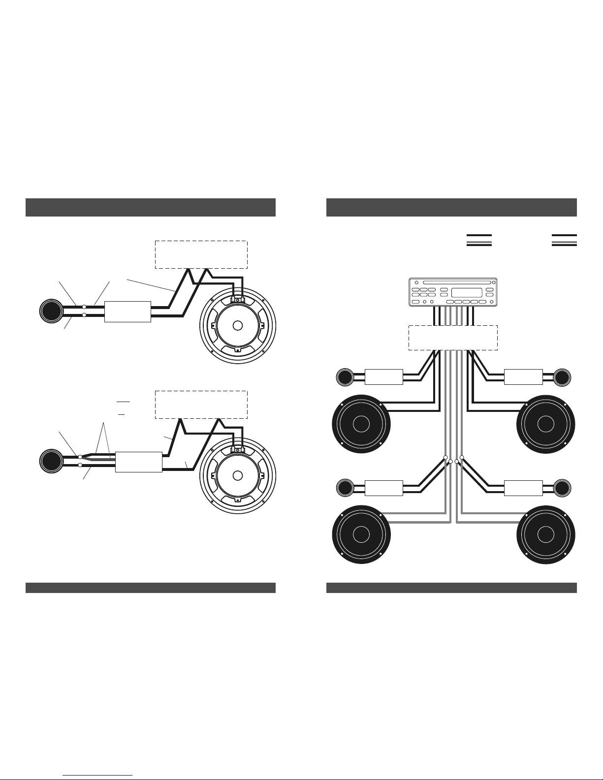
1. Follow the wiring diagrams figures 5and 6 to connect the loudspeaker system to your
automobile radio and possibly to an amplifier. Be very careful of correct polarity of all
connections. (+ to +, - to -)
The tweeters should only be installed through a crossover.
2. Replace the automobile battery connector and test the loudspeaker system.
Caution: Do not apply power to the tweeters without first installing crossovers.
Important!
Correct high frequency polarity in the automobile
The correct polarity of tweeter to woofer is a decisive factor for the sound quality of the
entire sound system. A false polarity can even "destroy” the sound of the best
loudspeaker system.
In some cases a polarity reversal (exchanged positive and negative poles) of both
tweeters can result in sound quality improvement. This can result from the mounting
position, from the distance between loudspeaker and listener or also from the sound
reflections in the automobile. Since this is very specific, it cannot be decided until the
loudspeakers have been mounted in the automobile.