Page 8
counter clockwise. To decrease the throttle’s
travel, thus decreasing the maximum speed,
turn the throttle stop bolt clockwise.
The throttle cable should be adjusted so there
is 2mm, (1/8”) free travel at the lever before
the throttle starts to open.
Rear Brakes
This vehicle is equipped with a mechanical
drum rear brake that is both the running
brakes and the parking brake.
The brake is controlled by the long brake
lever on the left-handle bar.
The rear brake is the primary stopping brake
on your vehicle. Using the rear brake to stop
your vehicle will prevent steering control loss.
Parking Brake
The rear brake lever has a button located at
the pivot point to lock the brake in the, “O”, on
position. This should be engaged as a parking
brake whenever the vehicle is not in operation.
This feature should be engaged in order to
start the engine. The brake lever has a safety
switch built in to prevent the engine from
starting while the brake is disengaged.
If your engine fails to start, ensure that the
engine stop switch is in the on, “O”, position
and that the parking brake is engaged.
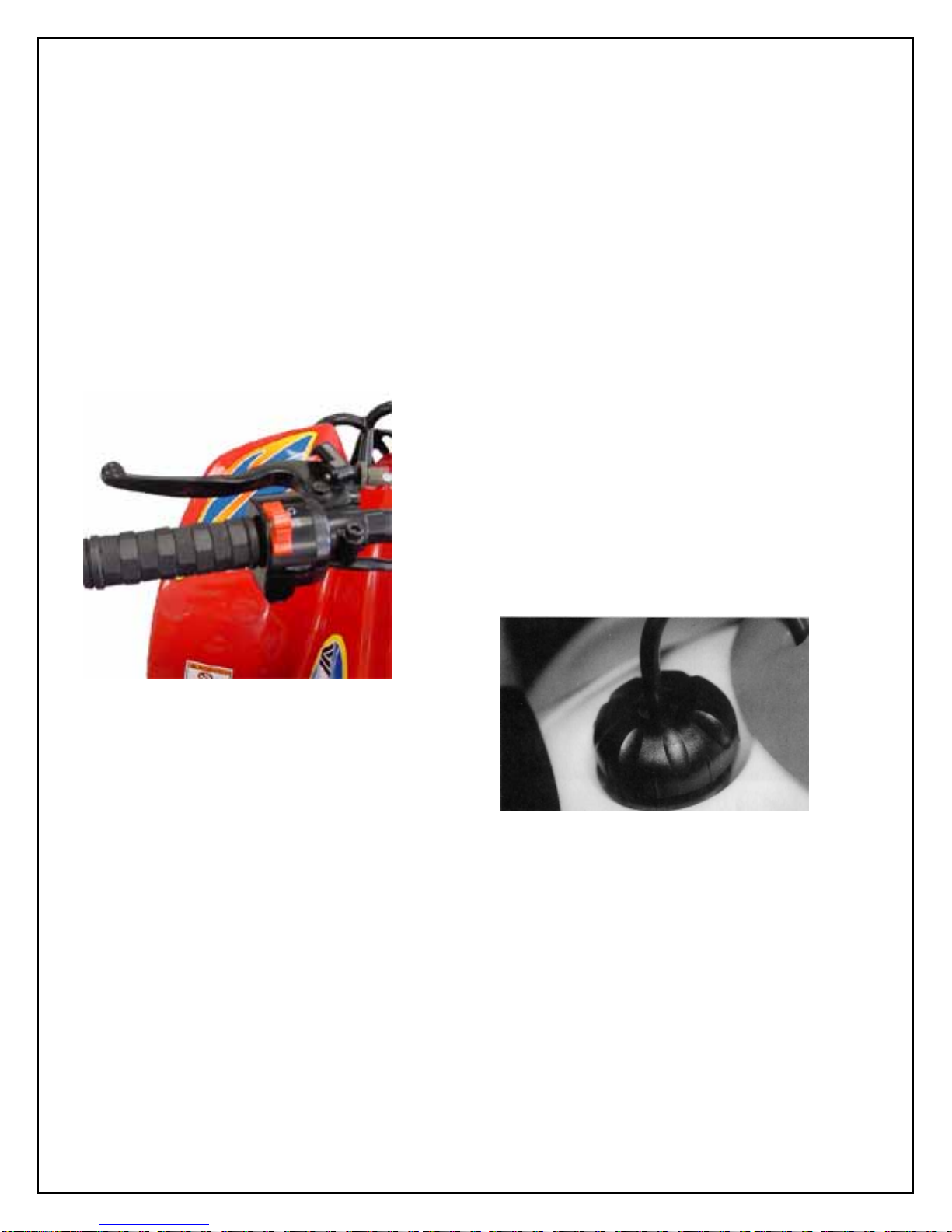
Safety Tether Switch
The Viper Jr. model is equipped with a safety
tether switch. It is located on at the rear of the
vehicle under the rear fender. The switch cap
must be fully engaged for the vehicle to run.
The cap is tied to a tether that can be worn by
the ride or control by a supervising adult. The
vehicle engine can be stopped by pulling on the
tether until the switch cap becomes disengaged.
This action will stop the engine.
Fuel Tank
The fuel tank fill cap is located on top of the unit
just ahead of the seat. The cap contains a vent
to prevent a vacuum from forming in the tank as
fuel is used. The vent tube must be attached to
the cap and inserted in the vent tube holder hole
of the handle bar cover while operating the unit.
The fuel cap vent and vent tube must be clean
and clear of obstructions for the unit to operate
normally. You can check the vent and vent tube
by blowing air through the tube. If you can not
blow through the vent tube and cap you must
clean the vent and tube or replace them.
Every time you refuel your unit, check the rubber
seal inside the cap for cuts, tears and dirt. Clean
or replace the seal if it becomes worn or torn.
The seal must be in good condition to insure a
proper seal of the cap to the tank to prevent fuel
spills. DO NOT allow dirt or other debris to enter
the tank when refueling.
Replace the cap if damaged or if it will not seal
to the tank.


 User manual")