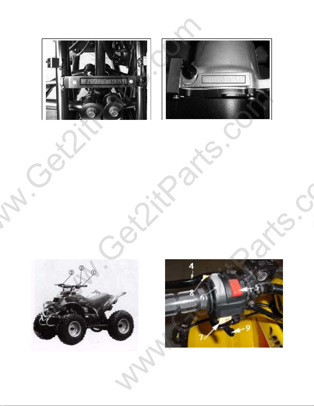
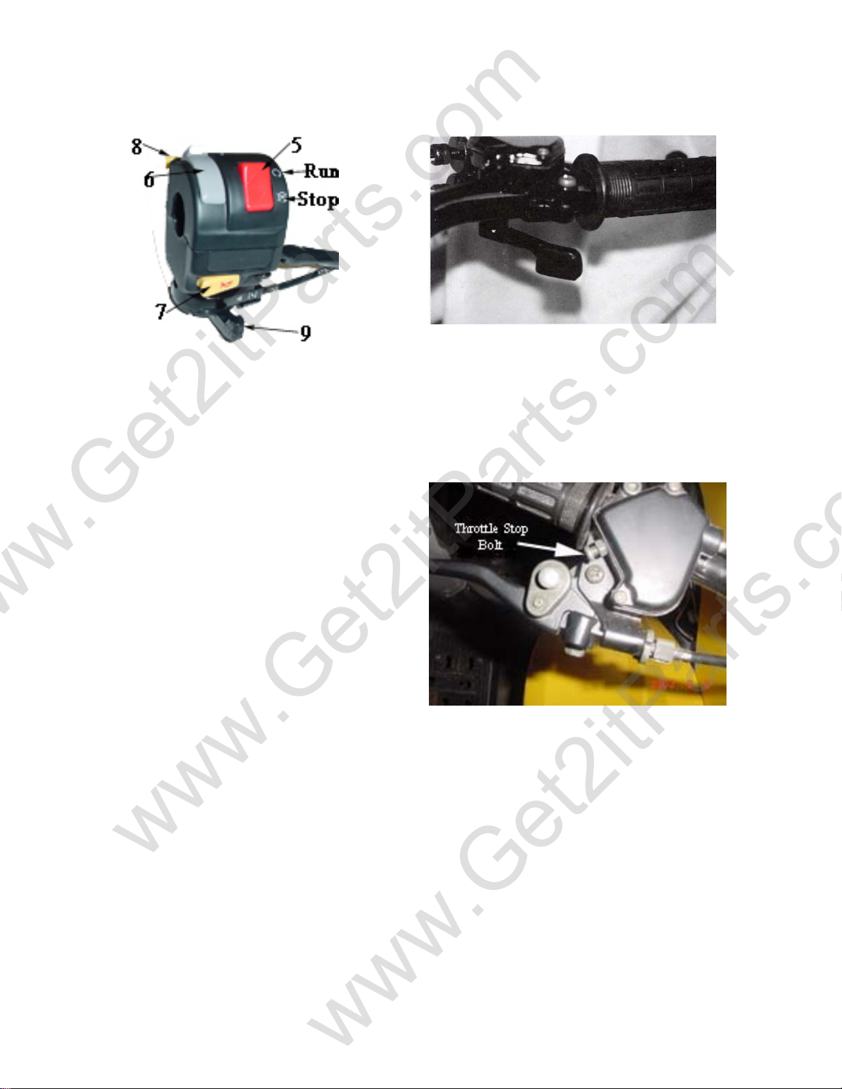
Eton 2006 Viper 70 User manual

E-TON
VIPER
OWNER’S MANUAL
Viper 50M, Viper 70, Viper 90
and Viper 90R
www.Get2itParts.com
www.Get2itParts.com
www.Get2itParts.com

www.Get2itParts.com
www.Get2itParts.com
www.Get2itParts.com

Page 1
Important Notices
READ and UNDERSTAND this owner’s manual
Both the operator and the adult supervisor should completely read and understand this
owner’s manual before operating this vehicle. This owner’s manual will instruct you in the safe
operation of the vehicle.
NO Passengers
This vehicle was designed for operation ONLY by the operator, (Driver). The load limit
and seat configuration is designed for the operator ONLY. It is not safe to carry passengers on
the vehicle.
ADULT Supervision and Instruction are REQUIRED.
This vehicle MUST NOT be operated by a youth without Adult supervision and
instructions. Unattended operation without adult supervision could result in injuries. E-TON
recommends that both the operator and the adult supervisor attend an ATV safety instruction
course.
ALWAYS Wear Protective Clothing
While operating this vehicle, the driver must always wear protective clothing. Protective
helmet with face shield, elbow and knee pads, long leg pants, gloves and hard soled boots
should always be worn when operating this vehicle.
OFF ROAD Use ONLY
This vehicle is designed and manufactured for off-road use only. Operation on public
streets, roads or highways is illegal and very dangerous.
OBEY all State and local laws and regulations
Each state and local governing agency has laws and regulations for ATV operations. It
is the owner’s responsibility to know, understand and obey these laws and regulations.
SPEED RESTRICTION Devices
This vehicle is equipped with electronic speed limiting devices. Any attempt to change,
over-ride or bypass these devices may cause dangerous operating conditions.
Age Recommendations by model size
ATV Model Size ETON Models Minimum Age Weight Capacity
Under 70cc
RXL-40Ee
RXL-50M
RXL-70
6 years and older 70 Lbs
70 - 90cc RXL-90
RXL-90R 12 years and older 250 Lbs
over 90cc CXL-150 16 years and older 250 Lbs
150 cc CXL-150 16 years and older 300 Lbs
www.Get2itParts.com
www.Get2itParts.com
www.Get2itParts.com

Page 2
Table of Contents
Safety notes 3
Vehicle identification number location 7
Controls, switches and feature locations 7
Control feature operations
Engine stop switch 8
Manual Choke Lever 8
Throttle lever 8
Front & Rear Brakes 9
Parking brake 9
Safety Tether Switch 9
Remote Stop / Start Switch 9
Fuel System
Fuel tank 10
Fuel valve 10
Inline Fuel Filter 11
Engine Oil
Oil Tank 11
Oil Indicator light 11
Tires & Wheels
Tire inspection 12
Tire pressure 12
Spark Plug 12
Spark Arrester Screen 12
Air Filter 13
Braking Systems
Front Brake Inspection 13
Front Brake Adjustment 14
Rear Brake Inspection 14
Filling the Brake Fluid Reservoir 15
Purging Brake Line 15
Drive Chain 16
Throttle Lever 16
Electrical Battery 17
C.V.T. Air Filter (Transmission) 17
Transmission Gear Selector Control 18
ATV Break-In Procedure 18
Changing Transmission Oil 18
Pre-Operation Inspection 19
Starting procedure 19
Driving 20
Turning 20
Parking 20
Specifications
Viper 50M 21
Viper 70 23
Viper 90 & 90R 25
Maintenance Schedule 27
Maintenance Record Chart 27
Wiring Diagram Viper 50M 28
Wiring Diagram Viper 70 29
Wiring Diagram Viper 90 30
Wiring Diagram Viper 90R 31
Manufacture’s Warranty 32
Owner’s Notes 34
www.Get2itParts.com
www.Get2itParts.com
www.Get2itParts.com

Page 3
Safety Notes
1. Both the adult supervisor and youth operator must fully understand everything in this manual
before operating this vehicle.
2. This vehicle was designed for the operator only. NO PASSENGERS should be allowed on
this vehicle.
3. This vehicle is designed for operation on level, obstacle free off-road areas.
4. Riding this vehicle on public roads or highways is illegal. If it becomes necessary to cross a
public road or highway, the vehicle should be pushed across using extreme caution.
5. This vehicle MUST NOT be operated without adult supervision and instruction.
6. DO NOT operate this vehicle while under the influence of drugs, alcohol or other medication
that impairs judgment or coordination. Doing so can result in serious injury or even death.
7. Maintain a safe distance between your vehicle
and other vehicles with whom you are riding.
8. READ the owner’s manual carefully before
riding.
9. ALWAYS wear a helmet, face shield, elbow &
knee pads, hard-soled boots, gloves, and protective
clothing while operating this vehicle.
www.Get2itParts.com
www.Get2itParts.com
www.Get2itParts.com

Page 4
10. NEVER ride this vehicle unless it has
been properly maintained and adjusted.
Always perform a pre-ride inspection of your
vehicle. Look for wires, bolts and other
fasteners that may have come loose on
previous rides. Inspect the drive chain,
throttle and brakes for proper adjustment and
operation. Check the engine oil level in the oil
tank. Check fuel level and inspect for fuel
leaks. (Remember, you can ride further in 1
hour than you can walk back in 1 day!)
11. WARM UP your body with some exercises
before riding. This helps to make you alert and
prevent cramping and other discomfort.
12. LEARN TO RIDE this vehicle properly and
safely. Have an experienced rider teach you the
safe operation of your vehicle. E-TON
recommends you take an ATV riding course
before you first ride your vehicle.
www.Get2itParts.com
www.Get2itParts.com
www.Get2itParts.com

Page 5
13. NEVER REFUEL this vehicle when hot. Ask
your adult supervisor to refuel your vehicle.
Gasoline is extremely flammable and will ignite if
spilled on a hot engine or muffler. Never smoke
or expose the fuel to an open flame or spark
while refueling your vehicle. Always refuel your
vehicle in a safe place free of any ignition source.
14. NEVER run the vehicle in an enclosed area. The
exhaust gases from the engine contain CARBON
MONOXIDE which can be fatal if breathed in high
concentrations for an extended time.
15. HOT! The engine and exhaust system on
your vehicle become very hot during normal
operation. Touching these hot surfaces can
cause severe burns. Always assume that your
unit’s engine and exhaust system are HOT
unless you know that they are not.
www.Get2itParts.com
www.Get2itParts.com
www.Get2itParts.com

Page 6
Additional safety tips:
•Participate in an approved ATV safety education training program
•Always provide responsible adult supervision for ATV operators younger than 18 years of age
•Don't let youngsters ride full-sized ATV's
•Follow all safety recommendations of the ATV manufacturer
•Operate ATVs only during daylight
•Wear a helmet with face protection at all times
•Operate only four-wheeled ATVs
•Provide a drug and alcohol free environment
•Always use the buddy system
•Avoid riding in areas where contact with automobiles might be possible
•Drive ATVs on surfaces as recommended by the manufacturer
•Travel at speeds conducive to conditions and operator abilities
•Check on the conditions of the trails you will be traveling
•Know and understand local and state laws governing the use of ATVs
•Permit only one operator per ATV
•Insist on a "perfect fit" between the ATV and the physical, mental, and emotional maturity of the operator
•Use antenna flags and wear bright clothing to increase conspicuity.
•Use maps and compass if you are riding in an unfamiliar area.
•Make a mental note of landmarks; you may need them if you are stranded.
•If you are lost at night, do not move around. You will waste valuable fuel that you can use to ride safety in
the daylight.
•Carry a first-aid pack with you.
•Carry some snacks and a water supply with you.
•Carry equipment to handle medical and mechanical emergencies.
•Your vehicle field repair kit should include the following items;
othe manufacturer's tool kit
owire, tape, elastic cords,
opossibly locking pliers
oand a tow rope.
•Pre-Ride Inspection - Inspecting the condition of your ATV before each ride is very important to minimize
the chance of injury and maximize the enjoyment of your ride. It also helps ensures long term
performance of your ATV. Follow the owner’s manual guide to inspection and maintenance of your ATV.
A well maintained ATV will give you years of enjoyment.
•Watch out for thin ice which may be camouflaged by snow.
•Remember, you can ride further in one hour than you can walk in an entire day.
Age Recommendations by model size
ATV Model Size ETON Models Minimum Age Weight Capacity
Under 70cc
RXL-40E
RXL-50M
RXL-70
6 years and older 70 Lbs
70 - 90cc RXL-90
RXL-90R 12 years and older 250 Lbs
over 90cc CXL-150 16 years and older 250 Lbs
150 cc CXL-150 16 years and older 300 Lbs
www.Get2itParts.com
www.Get2itParts.com
www.Get2itParts.com

Page 7
Vehicle Identification Numbers
Your VIN RFZ______________ Eng. No._______________
Controls, Switches & Feature Locations
Locations of controls and features
1. Fuel Tank filler and vent tube
2. Front brake lever (Parking Brake Lock)
3. Throttle lever
4. Rear brake lever
5. Engine stop switch
6. Head lamp switch
7. Horn button
8. Engine starter button
9. Manual Choke Lever
Vehicle Identification Number (VIN)
is located at the front of the unit under
the front fender on a plate mounted
between the main frame rails.
Engine serial number
is located on the left-hand side of the
engine on the crankcase housing.
www.Get2itParts.com
www.Get2itParts.com
www.Get2itParts.com

Page 8
Engine Stop Switch
The stop
switch is a red colored rocker switch located
on the left-hand handle bar.
To start and run the engine, this switch must
be placed in the on, “O”, position.
The vehicle is also equipped with a safety
brake switch which will prevent the engine
from starting until the parking brake is
engaged.
To stop your engine, place the switch to the
stop, “X”, position.
In the stop, “X”, position the ignition system is
grounded preventing the spark plug from
firing.
This switch can also be used as a safety or
emergency stop switch.
Manual choke lever (9)
All Viper models are equipped with a
manually operated carburetor choke system.
This choke is operated by the lever at the
bottom of the left hand control switch.
When first starting the engine,(cold start),
place the lever in the full left position, (Choke
closed or on) As the engine warms return the
lever to the full right position. (Choke open or
off).
Throttle lever
The throttle lever is located on the right-hand
handle bar below the grip. To operate the throttle
lever, place your right thumb on the lever and
press forward to increase your speed. To
decrease your speed, reduce your pressure on
the lever and the spring tension will
automatically reduce your speed.
The travel of the throttle lever is controlled by the
throttle stop bolt.
As your operator gains more experience, you
can increase the throttle travel to allow for
additional speed to be obtained.
To increase the throttle’s travel, thus increasing
the maximum speed, turn the throttle stop bolt
counter clockwise. To decrease the throttle’s
travel, thus decreasing the maximum speed, turn
the throttle stop bolt clockwise.
The throttle cable should be adjusted so there is
2mm, (1/8”) free travel at the lever before the
throttle starts to open.
Control Features
www.Get2itParts.com
www.Get2itParts.com
www.Get2itParts.com

Page 9
Front and Rear Brakes
This vehicle is equipped with dual front
mechanical drum brakes and a rear hydraulic
disc brake. (Viper 70 Viper 90 & Viper 90R)
(Viper 50M is equipped with rear hydraulic
disc brake only)
The front brakes are controlled by the long
brake lever on the right-handle bar.
The rear brake is controlled by the long lever
on the left-handle bar.
The rear brake is the primary stopping brake
on your vehicle. Using the rear brake to stop
your vehicle will prevent steering control loss.
Use your front and rear brakes in combination
to control your speed while descending a
grade. Use caution not to apply too much
pressure to your front brakes so that the
wheels lock up, stop turning, and causing a
loss of steering control. If the front wheels
lock up, and stop turning, lightly reduce the
pressure on the front brake lever until they
unlock and start to turn.
Parking Brake
The front brake lever has a button located at
the pivot point to lock the brake in the, “O”, on
position. This should be engaged as a parking
brake whenever the vehicle is not in operation.
This feature must be engaged in order to start
the engine. The brake lever has a safety
switch built in to prevent the engine from
starting while the brake is disengaged.
If your engine fails to start, ensure that the
engine stop switch is in the on, “O”, position and
that the parking brake is engaged.
Safety Tether Switch
The Viper 50M and Viper 70 models are
equipped with a safety tether switch (optional on
Viper 90R). The switch is located on the left
hand side of the handlebars. The switch cap
must be fully engaged for the vehicle to start and
run.
The cap is tied to a tether that should be worn
around the rider wrist. In case of an emergency
a simple pull on the tether will disengage the
switch and stop the engine.
Remote Stop/Start Switch
The Viper 50M come equipped with a remote
Stop/Start key ring switch. (This feature is an
optional kit for the Viper 70 & Viper 90. A remote
Stop Only kit is optional for the Viper 90R).
The remote switch has two buttons, a Stop
button which will stop the engine when pressed.
The effective range of the switch is 30 feet
unobstructed.
www.Get2itParts.com
www.Get2itParts.com
www.Get2itParts.com

Page 10
Once the unit has been stopped with the
remote switch you must press the run button
in order for the unit to be restarted. This
action resets the remote receiver on the unit.
The unit may also be started remotely by
pressing both the Stop & Run buttons
together.
Safety Note: Always test the remote
switch before beginning a riding session. The
remote switch is operated by a battery which
should be replace one a year. You can obtain
a replacement battery at your local
department store.
Fuel Tank
The fuel tank fill cap is located on top of the
unit just ahead of the seat. The cap contains
a vent to prevent a vacuum from forming in
the tank as fuel is used. The vent tube must
be attached to the cap and inserted in the
vent tube holder hole while operating the unit.
The fuel cap vent and vent tube must be
clean and clear of obstructions for the unit to
operate normally. You can check the vent and
vent tube by blowing air through the tube. If
you can not blow through the vent tube and
cap you must clean the vent and tube or
replace them.
Every time you refuel your unit, check the
rubber seal inside the cap for cuts, tears and
dirt. Clean or replace the seal if it becomes
worn or torn. The seal must be in good
condition to insure a proper seal of the cap to
the tank to prevent fuel spills. DO NOT allow
dirt or other debris to enter the tank when
refueling.
Replace the cap if damaged or if it will not seal
to the tank.
Tighten the cap snugly, being careful not to over
tighten. Over tightening the cap can cause
damage to the cap or seal.
The fuel tank capacity is 4.5 liters, 1.2 gal,
including a reserve of 0.8 liters, 0.2 gal.
Use unleaded automobile gasoline with an
octane level of 91 or higher.
NEVER REFUEL YOUR ATV when the
engine is HOT. Wait 30 minutes after turning
off the unit before refueling. Spilling fuel on a
HOT engine could cause a fire. Wipe up any fuel
spills before re-starting.
Fuel Valve
The unit is equipped with a three way fuel valve
located on the left side of the unit just below the
seat.
The valve has three settings; “OFF”, “ON” and
“RES”. With the valve in the “OFF” position fuel
is held in the tank and is prevented from flowing
to the carburetor. The valve should be placed in
the “OFF” position whenever the unit is not being
operated. Place the valve in the “ON” position for
normal operation of the unit. This allows fuel to
flow to the carburetor for normal operating. The
“RES” position allows fuel to flow from the small
reserve in the tank to allow the unit to be taken
to a refueling location.
www.Get2itParts.com
www.Get2itParts.com
www.Get2itParts.com

Page 11
When you have to switch to the “RES”
position you must refuel the unit as soon as
possible.
ALWAYS CHECK YOUR Fuel level before
you start riding your ATV.
Remember: You can drive further in one hour
on your ATV than you can walk in one day.
Inline Fuel Filter
Your ATV is equipped with an inline fuel filter
to prevent dirt and debris from entering the
carburetor and engine.
Check the filter for dirt or damage before each
ride and at each refueling. Replace the filter if
dirty or damaged.
The filter should be replaced every 600 hours
of operation and at the start of each season.
To replace the filter, first turn the fuel valve to
the “OFF” position. Then carefully compress
the wire clamp rings until the clamp is free of
the fuel line. Slide each clamp away from the
filter about ¾”.
Remove the filter from the fuel line by holding
the line and pulling the filter. Install the new
filter by inserting the filter into the fuel line and
returning the clamps to the original position.
Turn the fuel valve to the “ON” position and
check for leaks. Inspect the fuel lines for cuts,
abrasions and deterioration. Replace fuel
lines as needed.
DO NOT start or operate the engine if the fuel
filter or lines are leaking. Leaking fuel can cause
a fire.
Engine Oil Tank
2 Cycle Engine
Your ATV uses 2 cycle oil to lubricate the engine.
The oil tank is located under the seat at the front
of the unit. Oil is drawn from this tank by an oil
injector pump when the engine is operating.
Oil Level Warning Light
The unit is also equipped with an oil level
indicator lamp. The lamp will light when the oil
level in the tank is low. When the lamp is lit you
MUST refill the oil tank.
www.Get2itParts.com
www.Get2itParts.com
www.Get2itParts.com

Page 12
DO NOT allow the engine to operate with
an empty oil tank. Doing so will result in
extensive damage to your engine. This
damage is not covered under the warranty.
Check the oil tank level manually during every
other refueling operation.
The oil tank capacity is 1.1 liters, 1.2qt.
Fill the tank with high quality JASO FC grade
2 cycle engine oil. Using lower grade oil can
cause exhaust smoke and result in damage to
your engine.
Your first tank of fuel should be a pre-mix fuel
with a 50:1 fuel to oil ratio. This will insure the
engine is lubricated and give the oil pump
time to bleed any air from the oil line that may
have occurred during shipping.
Tires and Wheels
Tire & Wheel inspection
It is important to inspect your tires and wheels
for damage and wear before each riding
session. Inspect each tire for cuts, tears and
punctures. Inspect the wheel rim for dents
and separation of the wheel from the tire bead.
Replace any tire or wheel found to be
damaged.
Operating your ATV with damaged tires or
wheels is dangerous. Damaged tires or
wheels can result in a sudden loss of tire
pressure and control which could result in
injuries.
Check your tire pressure before each riding
session and at each refueling operation. Always
check the pressure when the tires are cool. Use
the tire pressure gauge that came with your ATV
to check the tire pressure.
Tire Pressure
Recommended tire pressure is:
7psi Maximum (Hot – after riding awhile)
2psi Minimum (Cold – Before riding)
Wheel Nut torque 24-30 N/m (18-22 lb/ft)
Spark Plug
Replace spark plug at the beginning of each
season with a replacement plug
NGK - BPR7HS.
Disconnect spark plug wire.
Clean dirt from around spark plug base with
brush or air.
Remove spark plug with spark plug wrench.
Set the spark plug gap on the new plug to 0.023”
Install the new plug screwing it in finger tight and
then use the plug wrench to screw the plug in
another ½ turn.
Inspect the spark plug wire for cuts, nicks or
other damage. Replace as needed.
Spark Arrestor Screen
Required maintenance and cleanout:
1. After every 100 hours of operation the
muffler should be cleaned by removing
the clean out bolt by using a 12mm
wrench.
2. After every 60 hours of operation the
Spark Arrester has to be cleaned by
loosening the retaining nut using a 10mm
socket. Using pliers turn the sleeve of the
Spark Arrester counterclockwise and pull
out. Clean the screen with an exhaust
cleaning solution and replace, securing it
by tightening the retaining nut.
3. After every 200 hours of operation the
Spark Arrester has to be replaced by
loosening the retaining nut using a 10mm
socket or wrench. Using pliers turn the
www.Get2itParts.com
www.Get2itParts.com
www.Get2itParts.com

Page 13
sleeve of the Spark Arrester
counterclockwise and pull out.
Replace a new Spark Arrester and
secure it by tightening the retaining nut.
Air Filter
Air Filter Maintenance
To maintain the highest performance from your
engine and to reduce excessive wear that could
cause engine failure the engine requires a
continuous flow of clean air. Air is taken into the
engine through an air filter to clean the air prior
to mixing it with fuel and oil in the carburetor.
During normal operation the filter
accumulates dirt from the air and will need to
be cleaned to maintain the proper air flow.
The filter should be cleaned every 30 days,
more often if you ride in a dusty or dirty
environment and the element should be
replaced every year.
The air filter box is located on the left side of the
engine under the front fender. It is a black box
about 6” square and is attached to the
crankcase with two bolts and the carburetor by
a tube.
To clean the filter
Remove the air filter box cover.
Remove the filter element from the air box.
Wash the element in a non-flammable solvent
such as Air-Filter cleaner from your local auto
parts dealer.
1. Dry the element completely before
continuing.
2. Soak the element in clean engine oil until
completely saturated.
3. Squeeze out the excess oil until the
element does not drip any oil.
4. Allow the element to dry then reinstall the
element and cover.
Braking Systems
Your ATV unit is equipped with dual front
mechanical drum brakes and a rear hydraulic disc
brake. The front brakes are applied by squeezing
the brake lever on the right-handle bar, while the
rear brake is applied by squeezing the brake lever
on the left-handle bar.
Proper maintenance of the brake system is a
necessary part of safe operation of your unit. The
brake systems should be inspected and tested
before each riding session.
Front Brake System Inspection
Visually inspect the brake cables for any signs of
wear. Inspect the cables for frays and kinks that
inhibit the free movement of the cable. Replace
frayed or kinked cable before operating your unit.
Inspect the cables for rust or corrosion. Replace any
brake cable that show signs of corrosion as this
could cause a reduction in cable strength that can
lead to the cable breaking.
Inspect the brake arm, spring, rod and fastener for
signs of wear or damage. Operate the brake lever
while watching the brake mechanism for proper
operation. Tighten, repair or replace parts as needed
to insure safe brake operation. Clean any build-up of
mud or debris from the brake mechanism.
The brakes are equipped with a wear indicator to
alert you when your brake shoes need replacing.
Apply light pressure to the brake lever and slowly
push the unit forward. If you hear a high pitched
metallic scraping sound, you need to replace your
brake shoes. The minimum shoe lining thickness is
1.5mm.
DO NOT RIDE A UNIT WITH WORN
BRAKE SHOES.
Test the brakes by applying pressure to the brake
lever and trying to push the unit forward. If the
www.Get2itParts.com
www.Get2itParts.com
www.Get2itParts.com

Page 14
wheel rotates while the brakes are applied,
adjust the brake cable until the wheels no
longer rotate.
(See Brake Adjustment)
Brake Adjustment
Adjust the brake cable so that the lever has
zero free play and a minimum clearance of ½”
between the lever and the handle grip when the
brake is fully applied. Adjust the cable by using
the adjustment wheel where the cable attaches
to the lever assembly. After obtaining the
correct adjustment, insure that the locking nut is
tightened securely against the adjusting wheel
to prevent the adjustment wheel from turning
due to vibration. Keep your brake cables
lubricated with a high quality cable lubricant to
prevent rust and corrosion. The cables should
be lubricated every 60 days or more often if
operated in a dusty or wet environment.
Replacement of the brake shoes and cables
should ONLY be preformed by a qualified
mechanic.
Rear Brake System Inspection
Visually inspect the brake hose for any signs of wear
or leaks. Check the fluid level in the fluid reservoir by
checking the site glass for the level.
The fluid level should fill at least ¾ of site glass
when the unit is setting on a level surface.
Test the brakes by applying pressure to the brake
lever and trying to push the unit forward. If the wheel
rotates while the brakes are applied, check your fluid
level and brake pads. If the brake lever feels spongy
or does not stop when squeezed, you may have air
in the lines. All air must be purged from the brake
lines for the disc brake to operate properly. (See
purging brake lines).
After riding your unit, be sure to clean any build up
of mud, sand and dirt from the brake rotor skid plate.
This will protect the rotor disc from rust and
corrosion.
To Fill the Reservoir
Remove the reservoir cover by removing the two
cover bolts.
www.Get2itParts.com
www.Get2itParts.com
www.Get2itParts.com

Page 15
Fill the reservoir to 1/8” from top with Dot-3 SAE-
J1703 grade brake fluid.
Caution: DO NOT allow dirt to fall into the
reservoir.
Refold the cover gasket as shown in picture and
replace cover and bolts
Purging Brake Lines
For the hydraulic brake system to operate safely,
the brake system must be purged of air in the
lines and reservoir.
To bleed the air will require two people to perform
the following procedure.
1. Place a drain pan under the brake caliper to
catch the fluid.
2. Open the bleeder valve ½ turn counter
clockwise.
3. Squeeze the brake lever to expel air from the
system.
4. While holding the brake lever, close the
bleeder valve.
5. Repeat steps 2 through 4 until the brake fluid
coming from the bleeder valve is a solid
stream without any air, then close the valve
and replace rubber protection cap.
6. Test the brake system by squeezing the
lever, the lever should feel firm and stop
without fading.
www.Get2itParts.com
www.Get2itParts.com
www.Get2itParts.com

Page 16
Drive Chain
The drive chain will stretch with use and will
require periodic adjustments. To check the chain
tension, remove the chain guard and measure the
slack.
The amount of slack in the chain should not
exceed 10-20mm or ¼” - ½”.
Inspect the drive and axle sprockets for worn,
damaged or broken teeth. Replace as needed.
Inspect the chain links for damaged, worn or
loose rivets. Repair or replace as needed.
Chain Slack Adjustment
Loosen the axle position lock bolt slightly and turn
the chain adjuster nut to take up the excess slack
in the chain. Once the chain has been adjusted
to the proper tension retighten the axle position
locking bolt.
The chain should be kept well lubricated to
prevent excess wear and premature failure. We
recommend that you lubricate the chain every 15
hours of operation, or more frequently if needed,
with a high quality chain lubricant.
Throttle Lever
The throttle lever is located beside the right-
handlebar grip and is operated by using the right-
hand thumb. The lever is spring loaded and will
return to the idle position when you remove your
thumb from the lever. To accelerate the unit, simply
press the lever forward to open the throttle slide in
the carburetor. To slow the unit, reduce the pressure
on the lever or remove your thumb and the throttle
will return to the idle position automatically.
Adjusting the throttle cable
The cable should be adjusted to allow for ⅛” free
travel before the throttle engages the carburetor
throttle slide. To adjust the cable’s free travel, loosen
the locking nut of the cable adjuster, and turn the
adjuster wheel until there is ⅛” free travel in the
lever. Tighten the locking nut to secure the adjusting
ring.
The speed of the unit can be adjusted by adjusting
the throttle stop screw to limit throttle travel.
www.Get2itParts.com
www.Get2itParts.com
www.Get2itParts.com

Page 17
Loosen the throttle stop screw locking nut and
turn the throttle stop screw clockwise to reduce
the throttle travel thus reducing the maximum
speed of the unit. Turning the stop screw
counter clockwise will increase the throttle
travel thus increasing the maximum speed of
the unit. Tighten the stop screw locking nut
when the desired throttle travel has been
established.
NOTE: Your unit includes an electronic speed
control that is set to limit the maximum speed of
the unit to the standards set by the CPSC for
the age of the rider the unit was designed for.
Electrical Battery
The unit’s battery is located under the seat and
supplies electrical power to the unit. The battery
is a 12 volt jell acid type that contains no liquid
electrolyte. The battery should be removed from
the vehicle when stored for extended periods
and charged before being replaced in the unit.
Use a trickle charger set at 12 volts to recharge
the battery to full charge before replacing it in the
unit.
When reinstalling the battery, be sure to connect the
red cable to the positive (+) terminal and the black
cable to the negative (-) terminal.
The battery should be replaced every three years or
when it no longer holds a charge.
Do not expose the battery, for extended periods of
time, to freezing temperatures. If the battery has
been frozen it will need to be replaced. There is an
inline fuse on the positive lead of the battery to
protect the wiring system from over loads. If your
starter motor will not turn over and the battery is fully
charged, check the inline fuse on the unit.
Replace the fuse with a 7A fuse.
C.V.T. Filter
This unit is equipped with an air filter for the
C.V.T. transmission. It is located on the left-
hand side of the engine, just ahead of the kick
starter spindle. The filter will accumulate dust
and must be cleaned periodically to maintain
normal vehicle operations. Inspect and clean
the filter every 30 operating days, more
frequently if operated in a dusty environment.
To clean the filter, remove the two cover bolts
and remove the filter. Clean the filter element
in a non-flammable solvent and let dry
completely before reinstalling. Replace the
filter element and the cover.
www.Get2itParts.com
www.Get2itParts.com
www.Get2itParts.com

Page 18
Transmission Gear selector
Viper 90R (only)
The Viper 90R model is equiped with a
transmission gear selector switch
mounted on the right hand side of the
handlebars. The switch has three
positions (“R” “N” “F”).
“R” = Reverse
“N” = Neutral
“F” = Forward
The selector must be placed on “N” to
start the engine. Once the engine is
started, engine the brake lever and move
the selector switch to the desired direction
of travel.
Always be sure the vehicle has come to a
complete stop and the brake lever is fully
engaged before turning the selector
switch. Always pause in the “N” neutral
positon for a few seconds when shifting
from forward to reverse or from reverse to
forward, this allows the transmission time
to disengage and resycronize.
ATV Break In procedures
Your ATV requires a break in period just as with
all other internal combustion engines. This
period allows the engine parts to seat and wear
properly without undue strain which can cause
premature failure.
1. For the first two weeks of operation do
not run your ATV at full throttle for
extended periods of time.
2. Your first tank of fuel should be a pre-
mixture of fuel and oil at a 50:1 ratio. This
will insure that the oil pump system has
been primed and bled of air that may
have occurred in shipping.
3. Do not operate the unit at more than 85%
of maximum speed.
4. Do not over rev the engine.
5. Use light braking pressure to allow the
brake pads to seat to the rotor and drums.
Changing Transmission Oil
1. Place an oil catch pan under the unit
directly below the transmission box.
2. Remove the transmission box drain plug
located on the bottom of the transmission
box on the underside of the unit.
3. Remove the transmission box fill whole
plug locate on top of the transmission
box near the oil tank bracket on the left
hand side of the unit.
www.Get2itParts.com
www.Get2itParts.com
www.Get2itParts.com
This manual suits for next models
3
Table of contents
Other Eton Offroad Vehicle manuals

Eton
Eton ATV3F-150 - SERVICE User manual

Eton
Eton Viper 40E (RXL-40E) User manual

Eton
Eton Yukon II User manual

Eton
Eton Viper Jr. (RXL-40) User manual

Eton
Eton ATV8E - SERVICE User manual

Eton
Eton VIPER 50 ST - SERVICE User manual

Eton
Eton CXL-150 - SERVICE User manual

Eton
Eton EXL-50 - SERVICE User manual

Eton
Eton Viper 150 User manual

Eton
Eton Vector 250R User manual

Eton
Eton ATV RXL 50 User manual

Eton
Eton ATV8F - SERVICE User manual

Eton
Eton ATV6A 90 User manual

Eton
Eton Viper 90R User manual

Eton
Eton DXL90 User manual

Eton
Eton VECTOR ST 250 User manual

Eton
Eton DXL90 User manual

Eton
Eton IXL 40 User manual

Eton
Eton ROVER User manual

Eton
Eton Lightning-AXL50 User manual