Wire fixed tooling
1
3.
2.
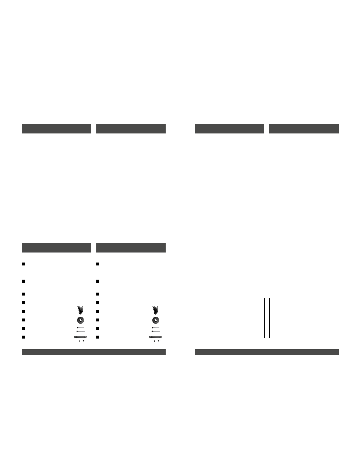
ADJUSTMENT
INSTALLATION PROCEDURE
ACCESSORIES
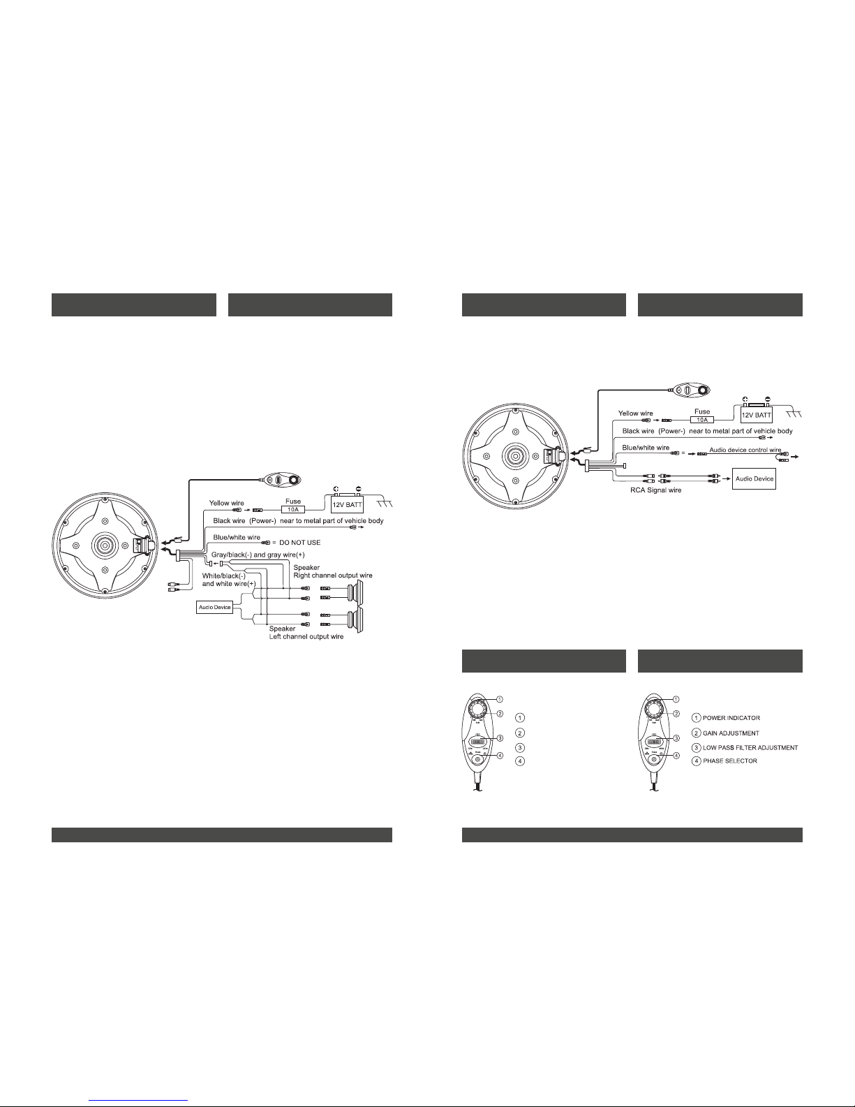
Use the supplied cable and wire harness and connect the outputs properly as
shown in the High-Level Low-Level Inputs wiring diagram as following.OR
Use only one of the audio inputs, otherwise, it may lead to audio interference.
Wiring Diagram 1(High-Level Input)
With control via the High-Level Inputs,first the speaker harness will need to be spliced
the wire side of the splitter.Then connect the white wire to the left [+],white/black wire
to the left [-] [it can be identified whether the left or right channel via the attached
harness label],grey to the right [+],and grey/black to the right [-] corresponding vehicle
wires, and finally plug the supplied harness into the High-Level Inputs/power matching
connector on the amplifier panel of the subwoofer.
Wiring Diagram 2(Low-Level “RCA” Input)
With control via the Low-Level Inputs [also referred to as RCA Inputs], connect the blue
color remote wire from the DQC-582T to the vehicle`s head unit so DQC-582T will be
turn on and off with systems.
Securely mount the subwoofer to
chass is with the provided bolt.
After the connection,place in the spare wheel
active subwoofer to the spare loction,make
sure to press down the subwoofer firmly.
If there is distortion of a popping noise from the subwoofer input level is too high.
If the subwoofer has prolonged use in this condition, this may result in deterioration
of performance or may cause damage to the subwoofer.
Wire fixed tooling
1
3.
2.
ADJUSTMENT
INSTALLATION PROCEDURE
ACCESSORIES
Use the supplied cable and wire harness and connect the outputs properly as
shown in the High-Level Low-Level Inputs wiring diagram as following.OR
Use only one of the audio inputs, otherwise, it may lead to audio interference.
Wiring Diagram 1(High-Level Input)
With control via the High-Level Inputs,first the speaker harness will need to be spliced
the wire side of the splitter.Then connect the white wire to the left [+],white/black wire
to the left [-] [it can be identified whether the left or right channel via the attached
harness label],grey to the right [+],and grey/black to the right [-] corresponding vehicle
wires, and finally plug the supplied harness into the High-Level Inputs/power matching
connector on the amplifier panel of the subwoofer.
Wiring Diagram 2(Low-Level “RCA” Input)
With control via the Low-Level Inputs [also referred to as RCA Inputs], connect the blue
color remote wire from the DQC-582T to the vehicle`s head unit so DQC-582T will be
turn on and off with systems.
Securely mount the subwoofer to
chass is with the provided bolt.
After the connection,place in the spare wheel
active subwoofer to the spare loction,make
sure to press down the subwoofer firmly.
If there is distortion of a popping noise from the subwoofer input level is too high.
If the subwoofer has prolonged use in this condition, this may result in deterioration
of performance or may cause damage to the subwoofer.
12 P connection couple
(Power cable, remote on wire,
speaker input wire, Ground wire)
6 m power extension
coupler (12AWG)
Speaker output wire
Remote on wire
Remote controller
Mounting bracket
Fixed screw (lock vehicle)
Wire xed tooling
12-Pin Anschlusskabelset
(Strom, Remote,
Signaleingang, Masse)
6 m Stromkabel
(12 AWG)
Lautsprecherkabel
Remotekabel
Kabelfernbedienung
Montagehalter
Gewindeschrauben
Zugentlastung
21
ETON bedankt sich ausdrücklich für den Kauf
des Aktivsubwoofers und beglückwünscht Sie
zu der Wahl dieses ausgezeichneten Produk-
tes.
Der ETON Aktivsubwoofer garantiert hervor-
ragende Leistungen. Die elektrischen, me-
chanischen und klanglichen Eigenschaften
bleiben über die gesamte Lebensdauer des
Produktes erhalten. Wir wünschen Ihnen viel
Freude beim Hören.
Bedienungsanleitung
Die vorliegende Bedienungsanleitung wurde
so konzipiert, dass Sie Ihnen eine korrekte
Installation ermöglicht. Sie enthält Informatio-
nen und grundsätzliche Vorgehensweisen für
die korrekte Funktionsweise des Produktes
und deren daran angeschlossenen externen
Geräte. Bitte lesen Sie die Bedienungsanlei-
tung sorgfältig, bevor Sie mit der Installation
oder dem Anschluss des Aktivsubwoofer be-
ginnen.
ETON expressly thanks you for deciding to
purchase this active subwoofer and congra-
tulates you on the selection of this excellent
product.
The ETON active subwoofer is a guarantee for
outstanding performance. The electrical, me-
chanical and tonal characteristics will be main-
tained at the original high standard throughout
the entire operational life of this product. We
wish you many pleasant listening hours.
Operating Instructions
The current operational instructions are de-
signed to ensure correct installation of the
amplier. They contain information and es-
sential procedures for the correct operation of
the product and its attached external devices.
Please carefully study the operating instruc-
tions before beginning with the installation or
the connection of the active subwoofer.
SicherheitshinweiseEinführung
Inhalt
Safety InstructionsIntroduction
Contents
Achtung !
Bitte lesen Sie alle Warnungen in dieser An-
leitung. Diese Informationen sind hervorgeho-
ben und eingefügt, um Sie über mögliche per-
sönliche Schäden oder Beschädigungen von
Sachwerten zu informieren.
Hörschäden
DAUERHAFTES AUSGESETZTSEIN VON
LAUTSTÄRKEN ÜBER 85dB KANN ZUR
SCHÄDIGUNG DES GEHÖRS FÜHREN.
VERSTÄRKER BETRIEBENE AUTOHIFI-
ANLAGEN KÖNNEN LEICHT SCHALLDRÜ-
CKE ÜBER 130 dB ERZEUGEN UND IHR
GEHÖR NACHHALTIG SCHÄDIGEN. BITTE
BENUTZEN SIE DEN GESUNDEN MEN-
SCHENVERSTAND UND VERMEIDEN SIE
SOLCHE RISIKEN.
Lautstärke und Fahrerbewusstsein
Der Gebrauch von Musikanlagen kann
das Hören von wichtigen Verkehrsgeräuschen
behindern und dadurch während der Fahrt
Gefahren auslösen.
ETON übernimmt keine Verantwortung für
Gehörschäden, körperliche Schäden oder
Sachschäden, die aus dem Gebrauch oder
Missbrauch seiner Produkte entstehen.
Attention !
Please read all warnings found in this manual.
This information is highlighted and included to
inform you of the potential danger of personal
injury or damage to property.
Hearing Damage
CONTINOUS EXPOSURE TO SOUND
PRESSURE LEVELS OVER 85dB MAY CAU-
SE PERMANENT HEARING LOSS. HIGH
POWERED AUTO-SOUND SYSTEMS MAY
PRODUCE SOUND PRESSURE LEVELS
WELL OVER 130 dB. THIS MAY CAUSE DA-
MAGE OF HEARING. USE COMMON SEN-
SE AND AVOID SUCH RISKS!
Volume and Driver Awareness
Use of sound components can impair your
ability to hear necessary trafc sounds and
may constitute a hazard while driving your
automobile.
ETON accepts no liability for hearing
loss, bodily injury or property damage
as a result of use or misuse of this
product.
ACHTUNG!
Sollen Karosseriebleche ausge-
schnitten oder entfernt werden,
nehmen Sie Kontakt mit Ihrer Fahr-
zeug-Vertragswerkstatt auf.
Bei Beschädigungen tragender
Karosserieteile kann die Betriebser-
laubnis erlöschen.
ATTENTION!
If sheet metal must be cut or
removed contact your authorized
car dealer for professional advice.
By damage to supporting body
structures the safety certicate
may be withdrawn.
Wire fixed tooling
1
3.
2.
ADJUSTMENT
INSTALLATION PROCEDURE
ACCESSORIES
Use the supplied cable and wire harness and connect the outputs properly as
shown in the High-Level Low-Level Inputs wiring diagram as following.OR
Use only one of the audio inputs, otherwise, it may lead to audio interference.
Wiring Diagram 1(High-Level Input)
With control via the High-Level Inputs,first the speaker harness will need to be spliced
the wire side of the splitter.Then connect the white wire to the left [+],white/black wire
to the left [-] [it can be identified whether the left or right channel via the attached
harness label],grey to the right [+],and grey/black to the right [-] corresponding vehicle
wires, and finally plug the supplied harness into the High-Level Inputs/power matching
connector on the amplifier panel of the subwoofer.
Wiring Diagram 2(Low-Level “RCA” Input)
With control via the Low-Level Inputs [also referred to as RCA Inputs], connect the blue
color remote wire from the DQC-582T to the vehicle`s head unit so DQC-582T will be
turn on and off with systems.
Securely mount the subwoofer to
chass is with the provided bolt.
After the connection,place in the spare wheel
active subwoofer to the spare loction,make
sure to press down the subwoofer firmly.
If there is distortion of a popping noise from the subwoofer input level is too high.
If the subwoofer has prolonged use in this condition, this may result in deterioration
of performance or may cause damage to the subwoofer.