etrailer e98988 Assembly instructions

e98988
e98988
etrailer.com ATV Utility 12 V
Electric Winch - 2500 Lb.
LIT-00114, Rev -

Page 2 e98988
Rated Single
Line Pull
2,500 lb. (1,134 kg.)
Application Utility/Shop/ATV
Motor 12VDC 1 HP Permanent Magnet
Power IN &
Power OUT Yes
Duty Cycle Rating 5% (45 sec at Max Rated Load;
14 min, 15 sec Rest)
Geartrain Single-stage Planetary
Gear Ratio 153:1
Freespool Yes
Brake Auto. Load Holding Dynamic
Drum (Dia. X L) 1.25″ X 2.8″ (32mm X 71mm)
Hook 1/4″ Eye Hook
Fairlead Hawse Fairlead
Wire Rope
Size / Type
Ø5/32″ x 50′ (Ø4mm X 15.2m)
Synthetic Rope
Battery 12VDC, Minimum 12 Ah
Battery Cables 10 gauge, 5.8′ (1.78m) long
Mounting Pattern 3.15″ (80mm)
Mounting Hardware Winch: 2x G8, M8-1.25 X 35mm
Fairlead:
2x G8, M8-1.25 X 19mm
Overload Protection In line Circuit Breaker
Sound Rating 85 dB
Overall Dimensions
(L X D X H)
11.25″ X 3.88″ X 4.25″
(286 X 99 X 108mm)
Weight 14.7 lb. (6.7 kg.)
IP Rating IP 65 - Winch and Controls
(resistant to water jets)
Layer Rated Line Pull Rope Capacity
12500 lb. (1134 kg.) 6′ (1.8m)
22045 lb. (928 kg.) 13.3′ (4.0m)
31731 lb. (785 kg.) 21.9′ (6.7m)
41500 lb. (680 kg.) 31.8′ (9.7m)
51324 lb. (600 kg.) 43.1′ (13.1m)
61184 lb. (537 kg.) 50′ (15.2m)
First Layer of Wire Rope Performance
1
Line Pull lb. (kg.) Line Speed fpm (mpm) Amp Draw (@ 12V)
0 (0) 13.3 (4.1) 10
1000 (454) 8.3 (2.5) 55
2000 (907) 4.1 (1.2) 106
2500 (1134) 2.7 (0.8) 132
Specifications
LIT-00114, Rev -

Page 3
WARNING SYMBOLS AND DEFINITIONS
This is the safety alert symbol. It is used to alert you to potential
personal injury hazards. Obey all safety messages that
follow this symbol to avoid possible injury or death.
Indicates a hazardous situation which, if not avoided,
will result in death or serious injury.
Indicates a hazardous situation which, if not avoided,
could result in death or serious injury.
Indicates a hazardous situation which, if not avoided,
could result in minor or moderate injury.
Addresses practices not related to personal injury.
Symbol Property or Statement
Wear heavy-duty, cut- and
abrasion-resistant leather gloves.
Wear ANSI-approved safety glasses.
Cut or sever hazard.
Roller entanglement hazard.
Hot surface burn hazard.
Fire hazard.
Caustic chemical hazard
from battery acid.
Explosion hazard.
Do not loop the wire rope around
object and hook onto itself.
Do not place finger(s) through hook.
Fingers may be caught and get
pulled into fairlead or drum.
Pull hook using strap only.
Symbol Property or Statement
Do not use winch in
overwind orientation. (Wire rope
enters/exits at the top.)
Use winch only in underwind orientation.
(Wire rope enters/exits at the bottom.)
VDC Volts Direct Current
AAmperes
CCA Cold Cranking Amperes
HP Horsepower
fpm Feet Per Minute
mpm Meters Per Minute
RPM Revolutions Per Minute
IP
International Protection rating
Classifies the degrees of protection
provided against the intrusion of solid
objects, dust, accidental contact, and water.
G8 Grade 8
A fastener strength rating.
e98988
LIT-00114, Rev -

Page 4
Important Safety Information
WARNING! Read all instructions carefully.
Failure to follow listed instructions could result in accident, injury and/or DEATH.
The warnings and instructions listed in this manual cannot cover all possible hazardous
conditions. Operate with caution.
Installation Precautions
1. Do not wear loose fitting clothing or jewelry,
while installing, servicing, or operating winch.
2. Wear ANSI-approved safety goggles and heavy-duty
leather work gloves during installation.
3. Before installation confirm that drill area is clear
of all obstructions and equipment that could be
damaged during drilling.
4. Mounting location and hardware
must support winch and load.
5. Use supplied power cords and rope listed
in manual only.
6. Do not route electrical cables near sharp edges,
moving parts, or hot equipment.
7. Ventilate area well before and while working
on battery.
8. Only connect to a clean, corrosion free battery.
9. Do not come in contact with
battery while making connections.
10. Remove all metal jewelry before working near battery.
11. Connect red wire to positive battery terminal
and black wire to negative battery terminal.
12. Insulate all exposed wiring and
terminals after installation.
13. Install winch and fairlead in underwind orientation, so
that the winch rope enters and exits the
winch at the bottom of the drum.
e98988
LIT-00114, Rev -

Page 5
Operation Precautions
1. Do not exceed load capacity.
2. Do not maintain power to the winch if winch
motor stalls. Verify that load is within rated capacity
outlined on page 2.
3. Wear ANSI-approved safety goggles and
heavy-duty leather work gloves during operation.
4. Do not disengage clutch under load.
Engage clutch before starting.
5. Keep clear of fairlead when operating.
Do not try to guide winch rope.
6. Use included strap to hold hook. Placing hands /
fingers through hook could cause them to be pulled
into fairlead / drum.
7. Stay out of the direct line of the winch rope when in
operation. Line breakage could cause damage to
equipment, injury, and / or death.
8. Do not use winch for hoisting or moving people.
9. (If Applicable) Do not use the hand crank to assist
winch operation.
10. Do not use ATV / UTV / vehicle to aid in winch
operation. This could place undue stress on the
winch rope and lead to rope breakage.
11. Disconnect battery cables before performing any
maintenance on the winch.
12. Inspect winch, winch housing, mounting hardware,
winch rope, and electrical cables for damage before
use. Damaged or broken equipment can lead to
accident, injury, and / or death.
13. Keep all bystanders from work area when operating
winch.
14. Only connect winch to appropriate pulling points
during operation. Do not "choke" load with winch
rope.
15. Do not use a recovery strap for winching. Recovery
straps are designed to stretch and can cause
accident, injury, or death if used improperly.
16. Do not operate winch if less than 5 full turns of winch
rope are on drum.
17. Ensure that winch rope is taut before beginning
winching operation. Failure to do so can lead to
binding of the winch rope on the drum.
18. If winch rope begins to get tangled, stop winching,
release winch tension with switch, and realign load.
19. Only winch with vehicle transmission in neutral and
parking break applied.
20. Winch operation is restricted to +/- 15° vertical
variation and +/- 25° horizontal variation from winch
center line.
21. If load must be pulled at angles outside of the range
indicated above, use an appropriately sized, rated
pulley (sold separately).
22. Winch motor will be hot after use, use caution.
23. Do not power hook all the way in to the fairlead. This
could cause the winch motor to overload and damage
the winch.
SAVE THESE INSTRUCTIONS.
e98988
LIT-00114, Rev -

Page 6
Installation and Setup
Mounting the Winch
1. Winch mounting location must be rated to maximum
winch capacity.
2. Winch must be placed on the center line of the
vehicle, and fairlead must be perpendicular to vehicle
centerline.
2*Ø0.33 in. / 8.5mm
3.15 in.
/ 80mm
3.94 in. / 100mm
2 in. /
51mm
8.31 in. / 211mm
11.25 in. / 286mm
2.83 in.
/ 72mm
4.13 in. / 105mm
1.25 in.
/ 32mm
Figure D: Winch Dimensions
3. Verify backside of mounting locations are clear of
obstructions and equipment that can be damaged by drilling
the mounting holes.
4. Use winch mounting plate as a
template to mark and drill holes for
mounting hardware.
5. Install the winch with specified
hardware.
Mounting Winch Components
1. Mount solenoid box so that:
a. Wires between winch components can be routed
without contacting sharp edges, moving parts, or
hot equipment.
b. Normal operation of vehicle components are not
affected.
c. Backside of mounting holes are clear of
equipment and obstruction.
2. Use bolt pattern as template for drilling pilot
holes.
3. Secure in place with mounting screws.
e98988
LIT-00114, Rev -
Page 7
Wiring
Disconnect all battery cables before starting installation
Use only a 12 V automotive battery, in good condition, for power
source.
1. Wiring must be routed to avoid sharp edges, moving
components, hot equipment, and contact from the
ground or environment while vehicle is in operation.
2. When wiring must be routed through drilled holes,
install rubber grommets to prevent wire breakage and
wear.
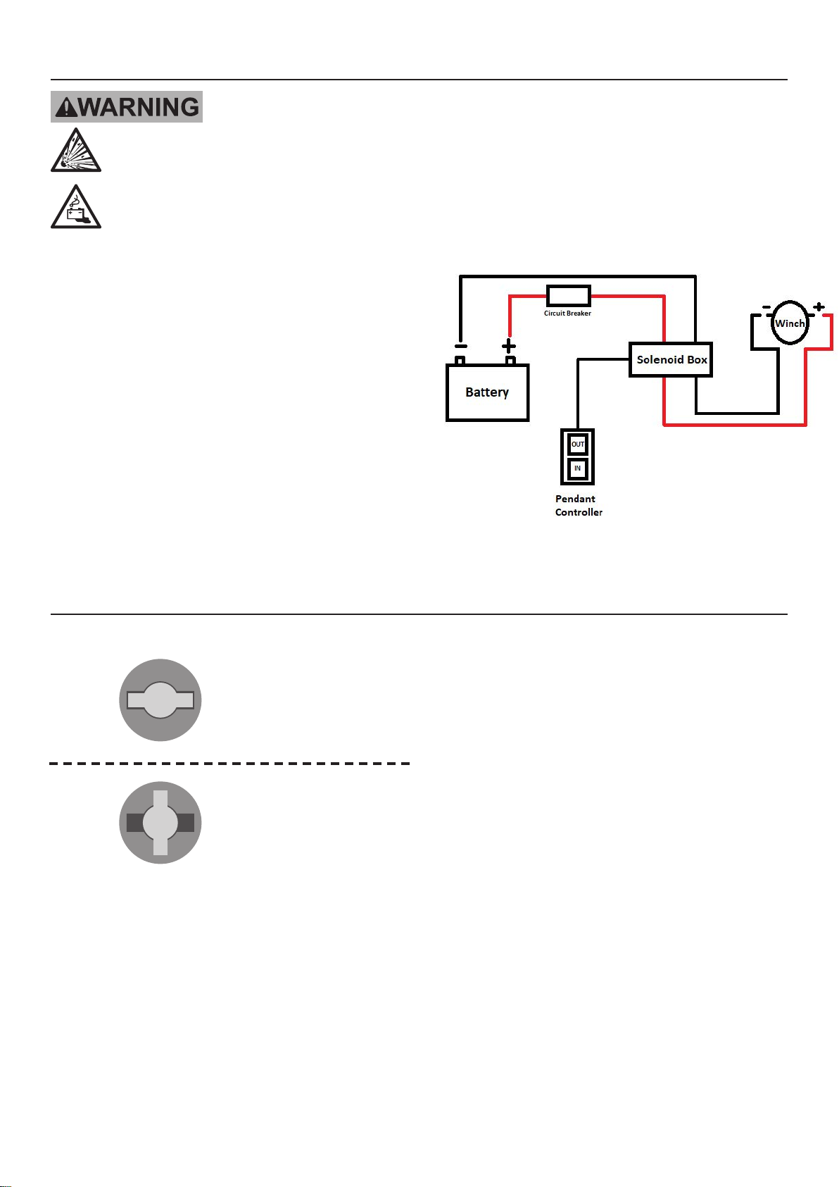
3. Refer to Figure E for wiring diagram.
Figure E: Wiring Connections
e98988
Clutch Operation
Shaft
Pin
Drum
End
If the pin rests
in the groove in the drum
the clutch is engaged.
Shaft
Pin
Drum
End
If the pin rests
on top of the end of the
drum the clutch is released.
2. To change clutch position:
a. Pull clutch knob out.
b. Turn it 90° while it is pulled out, then release it.
LIT-00114, Rev -

Page 8
Troubleshooting
Problem Possible Causes Likely Solutions
Motor overheats. 1. Incorrect power cords.
2. Winch running time too long.
1. Use only supplied power cords.
2. Allow winch to cool down periodically.
Motor does
not turn on.
1. Remote battery dead.
2. Loose battery cable connections.
3. Vehicle battery needs charging.
4. Solenoid malfunctioning.
5. Defective motor.
6. Water has entered motor.
1. Replace Remote battery.
2. Tighten nuts on all cable connections.
3. Fully charge battery.
4. Tap solenoid to loosen contacts. Apply 12
volts to coil terminals directly. A clicking
indicates proper activation.
5. Check for voltage at armature port with
Switch pressed. If voltage is present,
replace motor.
6. Allow to drain and dry. Run in short bursts
without load until completely dry.
Motor runs but
winch rope drum
does not turn.
Clutch not engaged. Move the Clutch Handle to the Engaged position.
Motor runs
slowly or without
normal power.
1. Insufficient current or voltage.
2. Loose or corroded battery
cable connections.
3. Incorrect power cords.
1. Verify supply battery charge.
Recharge if necessary.
2. Clean, tighten, or replace.
3. Use only supplied power cords.
Motor runs in one
direction only.
1. Defective or stuck solenoid. 1. Tap solenoid to loosen contacts.
Follow all safety precautions whenever diagnosing or servicing
the tool. Disconnect power supply before service.
e98988
LIT-00114, Rev -
Table of contents
Popular Winch manuals by other brands

HyQuest Solutions
HyQuest Solutions BAROSSA DDT700 user manual

Tractel
Tractel Carol TR Series Operation and maintenance manual

Bush
Bush II Series quick start guide

C-Max
C-Max VIGO Installation & operation manual

DINAMIC OIL
DINAMIC OIL SE45 Manual of use and maintenance

TAUBENREUTHER
TAUBENREUTHER 16 -831 Installation instruction


Andersen
Andersen 46ST product manual

AEV
AEV Bison installation guide

Red Winches
Red Winches HAWK - UTV Technical manual

Mile Marker
Mile Marker SEC8 Scout ES Installation & operator's manual

Huchez
Huchez MANIBOX VS Series instruction manual

Harken
Harken Radial Winch 70.2 ST Installation and maintenance manual