DINAMIC OIL SE45 Instruction manual

1/28
Manual of use and maintenance
SE45
Original instrucitions in english
Winch code: 93 45 00 10 0M
Edition: 01/2013
Manual code: M100
rev0 del 01/10/2012

2/28
Index
1 –GENERAL INFORMATIONS ......................................................................................................................................4
1.1 –Manufacturer’s identification data ........................................................................................................................4
1.2 –Winch identification data......................................................................................................................................4
1.3 –Using this instruction manual...............................................................................................................................4
1.4 –Exclusion of responsibility....................................................................................................................................4
1.5 –Instructions for technical assistance ....................................................................................................................5
1.6 –Receiving..............................................................................................................................................................5
1.7 –Warranty...............................................................................................................................................................5
1.8 –Standards and applied laws.................................................................................................................................5
1.9 –Safety symbols used in this manual.....................................................................................................................5
2 –TECNICAL INFORMATIONS......................................................................................................................................6
2.1 –Main parts and general winch description............................................................................................................6
2.2 –Description of machine functions.........................................................................................................................6
2.3 –Permitted use.......................................................................................................................................................6
2.4 –Uses not permitted...............................................................................................................................................6
2.5 –Environmental conditions.....................................................................................................................................6
2.6 –Safety devices......................................................................................................................................................6
2.7 –Residual risks.......................................................................................................................................................6
2.8 –Noise....................................................................................................................................................................6
2.9 –Electro-magnetic field...........................................................................................................................................6
2.10 –Overall dimensions.................................................................................................................................................7
2.11 –Technical data....................................................................................................................................................8
3 –SAFETY ......................................................................................................................................................................9
3.1 –General safety instructions...................................................................................................................................9
4 –TRANSPORTING, HANDLING AND INSTALLATION .............................................................................................10
4.1 –Packing the machine..........................................................................................................................................10
4.2 –Handling - Storage .............................................................................................................................................10
4.3 –Winch movement ...............................................................................................................................................11
4.4 –Assembly on base plate.....................................................................................................................................11
4.5 –Installation..........................................................................................................................................................12
4.6 –Hydraulic diagram ..............................................................................................................................................13
4.7 –Checks ...............................................................................................................................................................16
4.8 –Cable mounting..................................................................................................................................................17
4.9 –Pulleys................................................................................................................................................................18
5 –INFORMATION ABOUT ADJUSTMENTS................................................................................................................19
5.1 –Adjustments .......................................................................................................................................................19
6 –START UP INFORMATION......................................................................................................................................20
6.1 –Start up...............................................................................................................................................................20
7 –MAINTENANCE INFORMATION..............................................................................................................................21
7.1 –Warning..............................................................................................................................................................21

3/28
7.2 –Maintenance schedule.......................................................................................................................................21
7.3 –Cable..................................................................................................................................................................21
7.4 –Lubrication..........................................................................................................................................................22
7.5 –Cleaning operations ...........................................................................................................................................24
7.6 –Scrapping and disposal......................................................................................................................................24
8 –PROBLEMS AND SOLUTIONS................................................................................................................................25
8.1 –Troubleshooting .................................................................................................................................................25
9 –PARTS REPLACEMENT..........................................................................................................................................26
9.1 –Cable replacement.............................................................................................................................................26
10 –ANALYSIS OF THE RESIDUAL RISKS .................................................................................................................27
11 –NOTES....................................................................................................................................................................28
4/28
1 –GENERAL INFORMATIONS
1.1 –Manufacturer’s identification data
DINAMIC OIL S.p.a.
Via Togliatti, 15
41030 Bomporto (Mo) - Italy
telefono 059/812611 - telefax: 059/812606
e-mail: dinam[email protected]
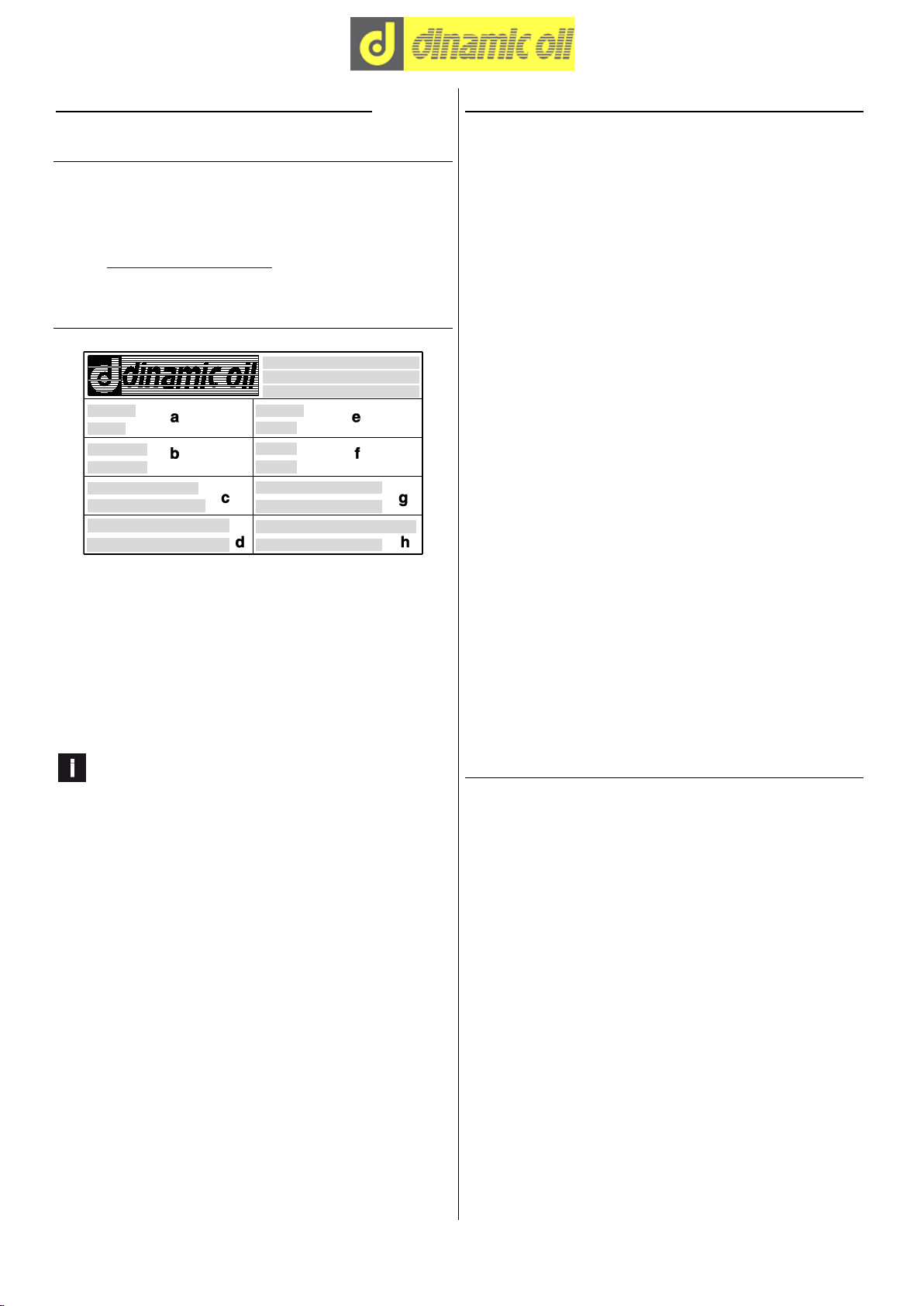
1.2 –Winch identification data
- Plate details
a = Model
b = Serial nr.
c = Max delivery
d = Max pull
e = Code
f = Year
g = Max speed
h = Hoisting pressure
Information
Under no circumstances must the data shown on the
identification plate be altered.
1.3 –Using this instruction manual
This manual contains the necessary information enabling
the operator to familiarize and correctly use the winch
(also simply described as “the machine”, although ac-
cording to Directive 2006/42/CE, the winch has been
classified as partly completed machine).
The information contained is intended for skilled op-
erators (1).
The original instructions are supplied by the manu-
facturer in English.
To fulfil legal or commercial requirements, the original in-
structions may be supplied by the manufacturer in other
languages.
If there are any doubts, whatsoever, concerning the cor-
rect interpretation of the instructions contained in this
manual, immediately contact the manufacturer for any
necessary clarifications.
To facilitate the consultation of the manual, it has been
divided into chapters of major concepts.
For quick searches please consult the index.
Reproduction or publication, in part or in whole, of the in-
formation contained in this manual is prohibited without
written authorization given by the manufacturer.
Using this instruction manual, for purposes other than
those described, without written authorization given by
the Manufacturer, is prohibited.
Any violation will be prosecuted according to the law.
(1) Only experienced people having the proper tech-
nical ability and knowledge of regulations and laws
will be able to carry out the necessary operations
and to identify and avoid possible damages during
handling, installation, operation and maintenance of
the machine.
1.4 –Exclusion of responsibility
The manufacturer is released from any responsibility for
damages deriving from:
- incorrect installation or which is not in accordance with
applicable laws;
- use of the machine by unauthorized and/or untrained
personnel;
- total or partial instruction disregarding;
- lack of maintenance;
- unauthorized modifications or repairs;
- non-designated uses;
- use of non-original spare parts and/or parts that are not
specific to the model;
- environmental circumstances beyond the manu-
facturer's control.

5/28
1.5 –Instructions for technical assistance
In case of machine malfunction or failure, for which spe-
cial technical assistance is required and for all spare
parts requests, contact directly the manufacturer or the
Reseller by phone or fax.
1.6 –Receiving
If any damages, faults or missing pieces are noted, con-
tact Dinamic Oil S.p.a. - Sales Office, immediately -
Winch Department - by phone 059/812611 or by fax
059/812606.
1.7 –Warranty
- Dinamic Oil S.p.a. warrants that its products are free
from all defects in materials or workmanship during the
warranty period indicated on the order confirmation Di-
namic Oil at the moment of purchase.
- During the warranty period Dinamic Oil S.p.a. will re-
pair or replace all parts or components that are unservi-
ceable due to ascertained defects in materials or work-
manship.
Under this warranty, any defective pieces must be sent to
Dinamic Oil S.p.a. which will examine them so as to de-
termine their cause.
- This warranty is strictly limited to the repair or re-
placement of products. Under no circumstances will the
manufacturer accept claims from customer demanding
reimbursement for direct or indirect damages of any na-
ture.
The merchandise may be returned only when previously
authorized by Dinamic Oil S.p.a.
- This warranty does not extend to “O” rings or gaskets in
general.
- This warranty does not cover any costs associated with
the installation or removal of defective parts from the
purchaser’s equipment.
- This warranty does not extend to any products that
have been repaired, modified or simply disassembled,
even partially.
- This warranty does not extend to any products that
have been subject to misuse or abuse, incorrect or care-
less assembly and tapering.
- This warranty recognized by Dinamic Oil S.p.a.
through its authorized sellers, disclaims all other warran-
ties of any nature whatsoever.
1.8 –Standards and applied laws
The machine was designed and constructed under cur-
rent directives 2006/42/CE and the following normes:
ISO 4301/01;
FEM 1.001 3rd edition (point 2,3,4,5,8).
1.9 –Safety symbols used in this manual
The following symbols will also appear throughout this
instruction manual. For safety purposes, these symbols
aim to highlight the operations which are considered
safety hazards. Therefore, it is absolutely indispensable
that the instructions highlighted by these symbols be res-
pected.
DANGER !!!
The information and procedures indicated by this symbol
which are not strictly respected will result in immediate
death or serious personal injuries.
ATTENTION !!!
The information and procedures indicated by this symbol
which are not strictly respected may result in death or
severe personal injuries.
CAUTION !!!
The information and procedures indicated by this symbol
which are not strictly respected may result in minor per-
sonal injuries or damages to the machine.
Information
Indicates important procedures and instructions.
6/28
2 –TECNICAL INFORMATIONS
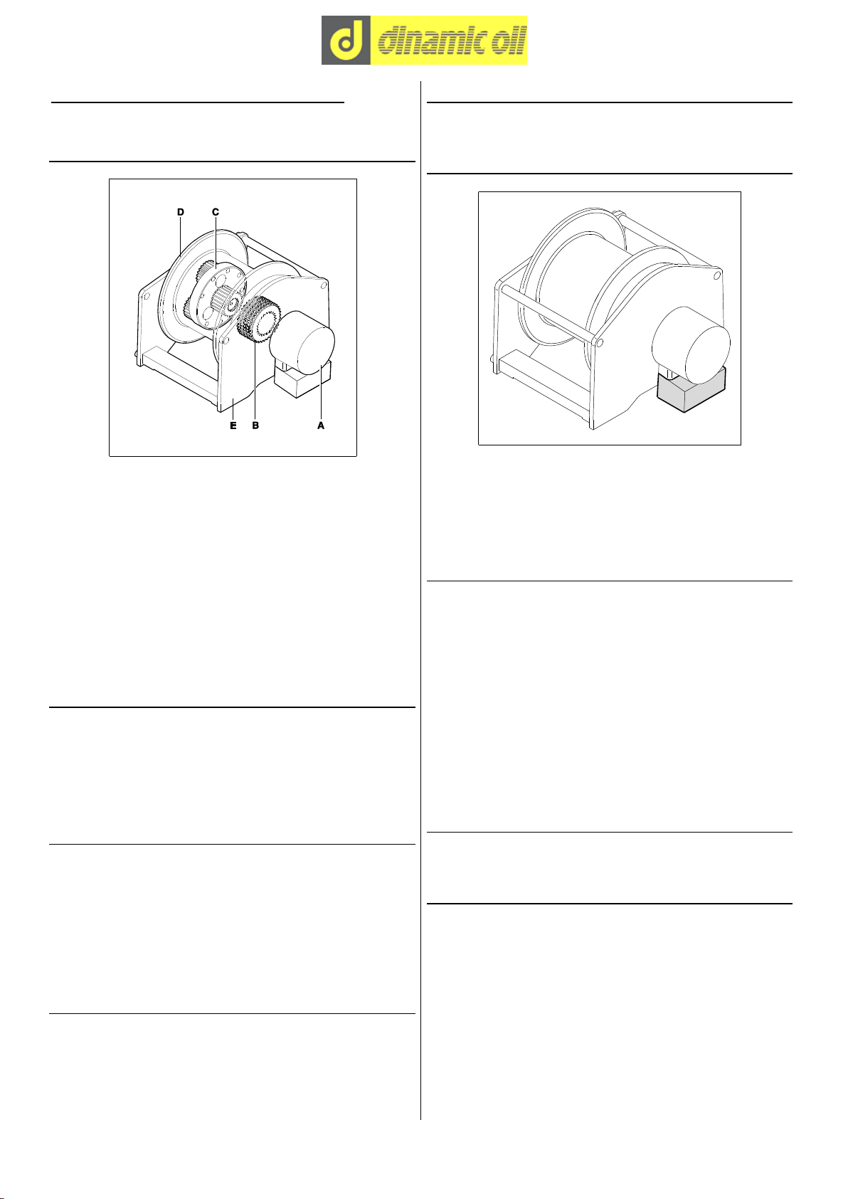
2.1 –Main parts and general winch descrip-
tion
- Legend
A = Hydraulic motor
B = Negative parking brake
C = Planetary reduction gear
D = Drum
E = Support structure
The winch is composed of a drum (in which an planetary
reduction gear and a negative parking brake are in-
serted) driven by a hydraulic motor, around which the
rope for load hoisting is wound: the whole unit is installed
on a support frame.
2.2 –Description of machine functions
The winch is commanded by the distributor of the opera-
tive machine on which it is installed. The rotation of the
drum winds and unwinds the rope to which the load is
applied. The brake is released when the motor is started
and is activated when the motor is stopped.
2.3 –Permitted use
The winch is designed to raise and lower loads by
winding and unwinding the cable around the drum. The
use of the winch with superior values to those listed in
the technical data is considered "improper use" and
therefore "not admitted"; insofar the builder declines
every responsibility in relation to the damages eventually
provoked to people or to things and cancels the warranty.
2.4 –Uses not permitted
Never use the winch to lift and transport people. It is for-
bidden to use the winch before machine on which it is
mounted has been declared compliant to the dispositions
of the Directive 2006/42/CE.
2.5 –Environmental conditions
Room temperature for a proper use: - 10°C; + 40°C.
2.6 –Safety devices
Valve for stopping and controlling the lowering
Fluid controlled, mounted directly on the hydraulic motor,
this part is essential for the safe functioning of the winch.
It prevents the load slipping out of the motor’s control
during lowering.
2.7 –Residual risks
Despite the observance of all safety norms and the em-
ployment according to the rules described in the manual,
there can still be some residual risks among which the
most recurrent are:
- friction;
- crushing between rope and drum;
- inverse rotation of the drum by human error;
- ejection of fluids due to the spillage of the oil in pres-
sure.
Keep in mind that the use of an any machine implicates
some risks. Face every type of operation with the maxi-
mum attention and concentration.
2.8 –Noise
The level of noise emissions detected is not relevant.
2.9 –Electro-magnetic field
The electro-magnetic discharges of the winch with cable
press - limit switch and load limiter are not significant.
7/28
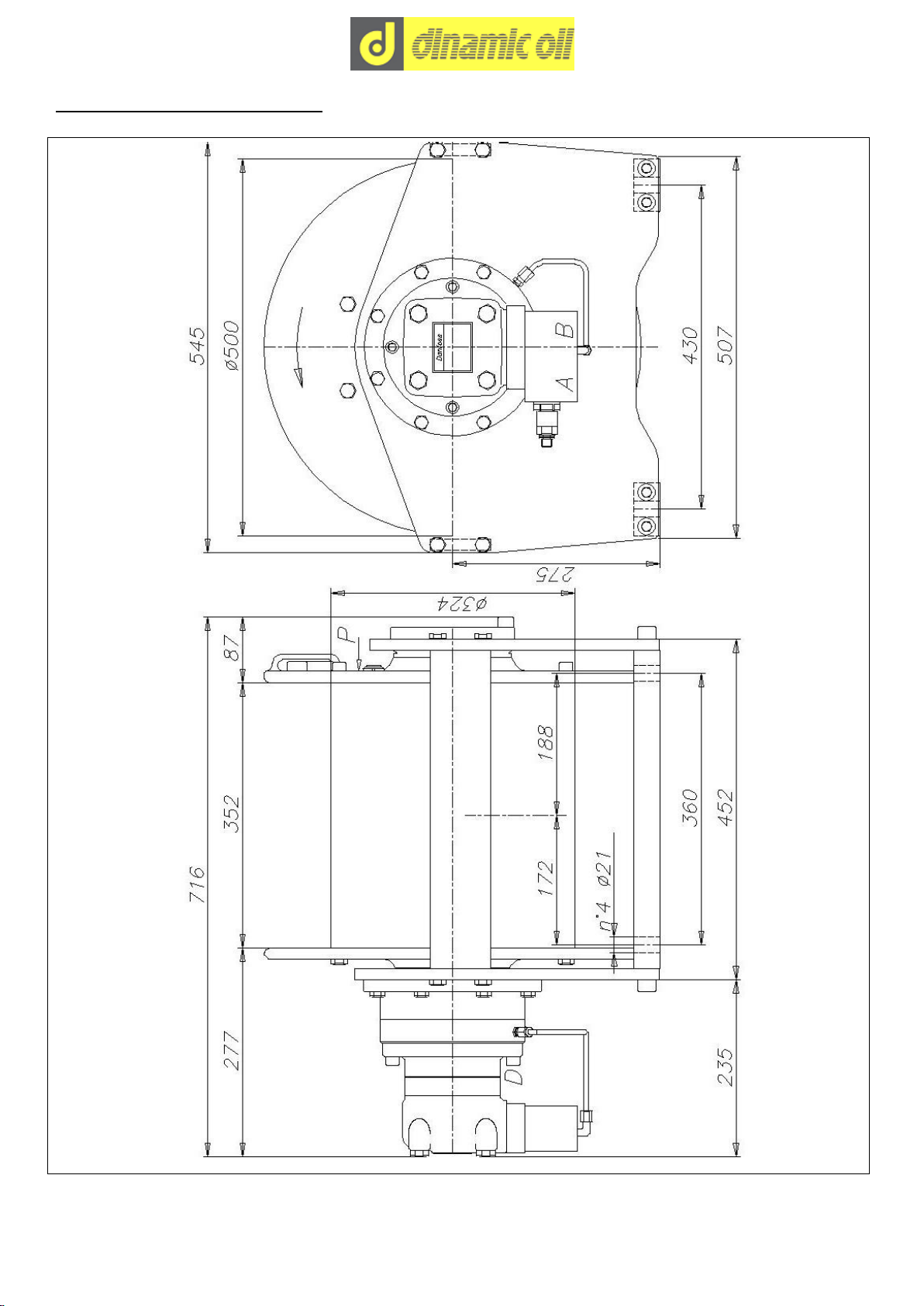
2.10 –Overall dimensions
V2 (A) = Hoisting line:
3/4” BSP
D = Drain line:
1/4” BSP
V1 (B) = Lowering line:
3/4” BSP
P = Lubrication oil plug:
1/2” BSP

8/28
2.11 –Technical data
Hydraulic motor:
SAUER DANFOSS OMTS
Motor displacement:
200 cm³
Maximum and minimun oil flow:
100/15 L/1’
Maximum counterpressure on the return line:
5 bar
Hoisting pressure:
230 bar
Negative brake:
static torque of 120 daNm
(with back pressure of 1 bar)
Minimun brake release pressure:
25 bar
Secondary safety brake:
not present
Planetary reduction:
ratio 1:18
Drum rotation direction(hoisting):
counterclockwise
Reduction lubrication oil:
HLP ISO VG 46 - 10 L
Fixing screws:
M20 –10.9 class (see “Tightening torques” chart)
Total weight of winch complete with lubricant:
265 kg
Recommended rope diameter:
16 mm
The winch is classified according to UNI ISO 4301/1 norm.
Rope layer
n°
1
2
3
4
5
6
Total line pull
daNm
5700
5200
4800
4500
Rope speed with capacity 100 L/1’
m/1’
28
30,5
33
35,5
Smooth drum rope capacity
m
23
47
73
102
Grooved drum rope capacity
m
- Tightening torques
Values for driving torques (Nm)
8.8 class
10.9 class
12.9 class
M10
50
73
86
M12
86
127
148
M14
137
201
235
M16
214
314
368
M18
306
435
509
M20
432
615
719
M22
592
843
987
M24
744
1060
1240
M27
1100
1570
1840
M30
1500
2130
2500

9/28
3 –SAFETY
3.1 –General safety instructions
- Read this manual carefully before attempting installation, use and maintenance operations.
- The user must be familiar with applicable safety rules and use modes of both the operating machine and the winch
installed, as he is responsible for his own safety as well as for any other person present near the machine working
area.
- All the operators must be suitably trained to use, adjust and operate of both the operating machine and the winch in-
stalled.
- Do not allow unauthorized personnel to use this machine.
- Do not start the machine, if it is faulty.
- Do not search for hydraulic leakage with bare hands, use a piece of paper or wood instead.
- A fluid coming from a very small hole might be almost invisible, and yet sufficient to penetrate the skin.
- If the fluid comes in contact with the skin, seek medical assistance immediately, for there might be risk of infection or
skin disease.
- Before removing any caps, plugs, or flexible tubes, make sure that there is no pressure in the hydraulic circuit.

10/28
4 –TRANSPORTING, HANDLING AND INSTALLATION
4.1 –Packing the machine
The packing of the machine is done according to the
agreements made with the Customer, taking into account
the distance and type of transport chosen.
In general the winches are packed in wooden boxes with
wood joists to facilitate harnessing and lifting.
Packing varies in relation to the quantity and type of
product.
The weight and dimensions are indicated in the transport
documents or on the package itself.
ATTENTION !!!
Do not tilt or turn the package upside down while lifting or
during transport.
4.2 –Handling - Storage
Use suitable means of transport to hoist and move the
packed unit, taking into account the type of packing.
If the package is moved with a fork-lift truck, make sure
the weight is balanced on the forks.
If the packages are moved with a hoist and, in any case,
with a hook, make sure that the load is balanced in the
sling.
Use lifting accessories that are suitable and legally certi-
fied.
While hoisting the unit and positioning it, take care not to
let it swing too much to prevent it hitting something.
The storage area must not be excessively damp or dusty.
The ambient temperature must be between - 20 °C and +
70 °C with a maximum humidity level of 90%, with no
condensation.

11/28
4.3 –Winch movement
For the hoisting procedures, strap the winch using two belts, which must be wrapped around the ends of the drum (fig.
A), or hook it on at the indicated points (fig. B) if present.
4.4 –Assembly on base plate
- Make sure that the surface the winch will be fastened to
is rigid enough and even.
- Place the winch on the surface and check that the fas-
tening plates lie perfectly flat on the fastening surface.
- If one of the 4 weight bearing points of application is
raised, insert a shim "A" to balance the unit and avoid
causing the unit undue tension during screw tightening.
- Tighten the screws with the correct tightening torque,
see section "2.11-Technical data".

12/28
4.5 –Installation
4.5.1 –Warnings
ATTENTION !!!
Winch installation and post-installation checks must be
carried out according to the applicable rules in the coun-
try where the machine is used.
Before assembly, make sure the winding direction of the
rope corresponds to the one indicated by the arrow ap-
plied on the winch (fig. 4.5.1).
Winches which rotate in the opposite direction to the
standard ones can be supplied on request (counter-
clockwise).
The winch can be mounted with the fastening surfaces
facing downwards, upwards or in any other position be-
tween the two.
4.5.2 –Hydraulic system
The distributor, therefore, must have an open centre (fig.
4.5.2) with an "H" configuration.
If the distributor presents a plurality of elements, connect
the winch to the last element closest to the outfeed side.
Connect the delivery opening of the element to the winch
motor in position “V2”.
The hydraulic system must meet the applicable rules and
realised with proper hoses, filters and valves.
13/28
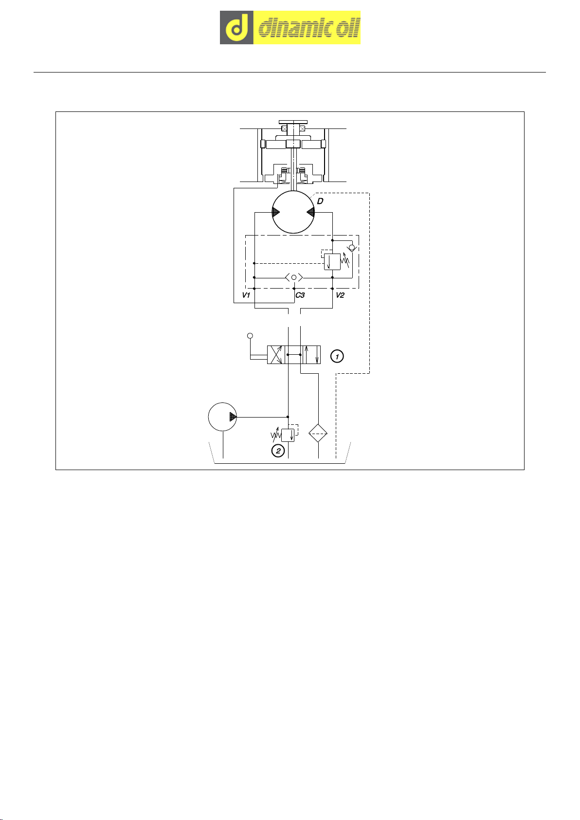
4.6 –Hydraulic diagram
- Hydraulic diagram for winch without accessories
V1
= Lowering line
1
= Open centre valve
V2
= Hoisting line
2
= Relief valve
C3
= Connection to brake
D
= Connection of drainage unit

14/28
- Hydraulic diagram for winch with limit switch-electrical cable press (if present)
V1
= Lowering line
3
= Discharge activation solenoid valve n.o
V2
= Hoisting line
4
= Resetting microswitch
C3
= Connection to brake
5
= Upwards stroke limit micro-switch
D
= Connection of drainage unit
6
= Downwards stroke limit microswitch
1
= Open centre valve
7
= Fuse
2
= Relief valve
8
= Limit switch activation key

15/28
- Hydraulic diagram for winch with cable press - hydraulic limit switch (if present)
V1
= Lowering line
1
= Open centre valve
V2
= Hoisting line
2
= Relief valve
C3
= Connection to brake
3
= Lower stroke limit hydraulic valve
D
= Connection of drainage unit

16/28
4.7 –Checks
- Check the pressure in the return line of the circuit
This measurement should be made by disconnecting the
two tubes from the valve and connecting them with a “T”
connection that may be linked to a pressure gauge with a
maximum scale of 60 bar.
Information
This counterpressure must be between 5 and 1 bar.
CAUTION !!!
Counter-pressure values higher than 5 bar dangerously
limit the braking torque, and values lower than 1 bar
could cause an insufficient motor power supply.
D = Distributor
M = Motor
V = Valve
m = Pressure gauge
P = Pump
R = “T” connection
- Make sure the control distributor has the gate open
D = Distributor
M = Motor
V = Valve
P = Pump
If you do not have sure indications you may proceed as
follows:
- disconnect the tubes from the valve and place their
ends in a container with a sufficiently large capacity; start
the pump while keeping the distributor in the center.
- If the two tubes do not release oil into the container the
distributor has the gate closed; if instead the two tubes
release oil, the gate is open.
CAUTION !!!
Make sure the oil flow does not cause the container
to overflow and as a consequence waste oil as well as
releasing polluting substances into the environment: if
there is a risk of this occurring, interrupt the test imme-
diately and resume it only after having replaced the con-
tainer with a larger one.
Informazione
Non disperdere l’olio esausto nell’ambiente, ma racco-
glierlo e inviarlo per lo smaltimento agli enti autorizzati.

17/28
4.8 –Cable mounting
- Installing cable with thimble
ATTENTION !!!
The winding direction of the rope must correspond to the
drum rotation direction indicated by the arrow.
Make sure that the emergency switch is working and that
a skilled operator is on hand and ready to stop the hoist
in the event of entangling or other irregularities that may
cause harm to the operator who is in the vicinity of the
cable.
If the cable is not sufficiently compact during the initial
assembly phase, when it is loaded it may become caught
up in the turns below and damaged.
1) Introduce the rope end into slot positioned on the drum
and then in the poket “A”.
2) Fold the rope around the thimble “B”. Then secure the
rope and thimble in the slot by pulling firmly.
- Installing cable with clamps
ATTENTION !!!
The winding direction of the rope must correspond to the
drum rotation direction indicated by the arrow.
Make sure that the emergency switch is working and that
a skilled operator is on hand and ready to stop the hoist
in the event of entangling or other irregularities that may
cause harm to the operator who is in the vicinity of the
cable.
If the cable is not sufficiently compact during the initial
assembly phase, when it is loaded it may become caught
up in the turns below and damaged.
1) Place the end of the cable in the slot on the edge of
the drum and then in the clamps "A".
Minimum protrusion “B” from the last clamp equal to 2
times the Ø of the cable.
2) Tighten the clamps screws.
For a correct winding, it is necessary to have a minimum preload of 5% of the breaking force of the rope. The breaking
force of the rope depends on the diameter and of the type of the rope and it has to be indicated in the rope certificate.
18/28
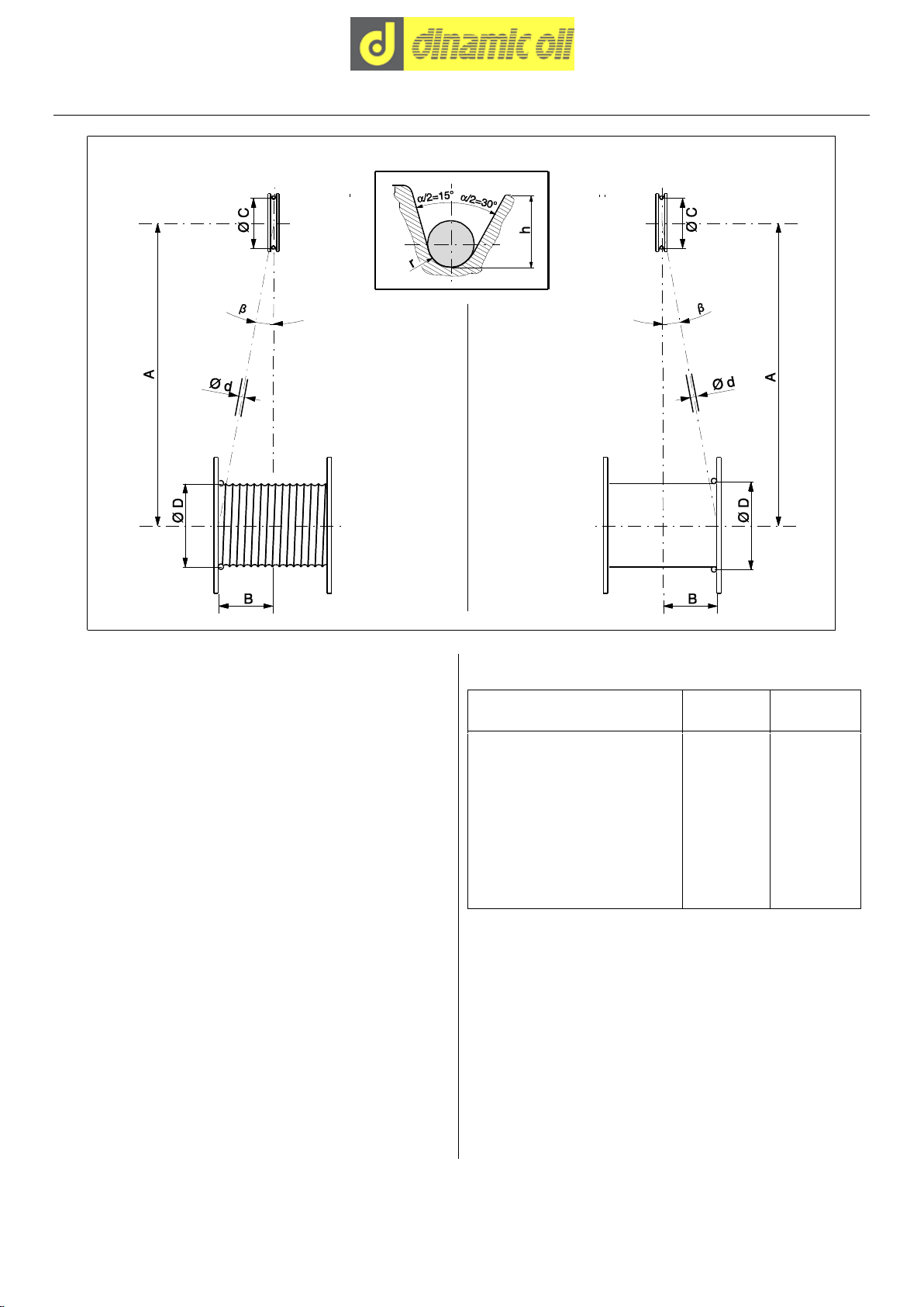
4.9 –Pulleys
- Legend
H
= Depth of the sheave groove
a
= Angle between sides of the sheave
d
= Nominal diameter of the rope
1
= Maximum angle “b”:
smooth drum = 1°30 (tg b= B/A)
threaded drum = 2° (tg b= B/A)
2
= Groove radius “r” = 0,5375 x d
3
= Groove minimum height “h” = 2 x d
4
= Angle between the pulley groove “a” = between
30° and 60°.
- Diameter choice according to gear class
Classification of mechanism
Drums
h1= D/d
Pulleys
h2= C/d
M1
11,2
12,5
M2
12,5
14,0
M3
14,0
16,0
M4
16,0
18,0
M5
18,0
20,0
M6
20,0
22,4
M7
22,4
25,0
M8
25,0
28,0
The size of the return pulley pitch diameter must comply
with the standard ISO 4308-1, according to the mechan-
ism classification.
Example:
for mechanism classification M5, the ratio between the
pulley pitch diameter and the diameter of the cable must
be no lower than 20.

19/28
5 –INFORMATION ABOUT ADJUSTMENTS
5.1 –Adjustments
- Calibrating the cable press limit switch (if present)
Information
Carry out the operation with the rope completely unwound.
1) Insert a shim “A” with the same diameter of the rope under the roller end.
2) Loosen screw “B”.
3) Turn lever “C” until screw “D” excites microswitch “E”.
4) Tighten screw “B”.

20/28
6 –START UP INFORMATION
6.1 –Start up
- Safety instructions
DANGER !!!
Before the intervention it is necessary to warn, with signs or other suitable means, that it is forbidden to get close and
stay in the danger zone due to the presence of suspended loads.
A danger warning plate, notifying the danger constituted by running cables that wrap around pulleys and drum, must
be placed on the machine. This prohibit anyone from approaching to the moving parts. This plate has to be reported in
the user manual of the crane or of the machinery on which it is mounted.
- Check hoisting part conditions (rope, hook, etc.) before using the winch.
- During start up operations, the operator and any member of the team shall keep a safety distance from the rope, to
prevent personal injuries in case of its breakage.
- It is standard practice to carry out the first few operations hoisting a modest load to no more than 1 metre from the
ground, in order to check that the lowering operation is controlled.
- Carry out manoeuvres gradually; avoid sudden jerking and load swivelling.
Other manuals for SE45
1
Table of contents
Other DINAMIC OIL Winch manuals


Popular Winch manuals by other brands


Harken
Harken 46.2 PTBBB Installation and maintenance manual

TORSO WINCH
TORSO WINCH CW02V12 Installation and operating instructions

Harken
Harken Performa Winch 20 STP Installation and maintenance manual

Tulsa
Tulsa RUFNEK 30 Service manual

EIVA
EIVA Ocean Enviro 10.4 user manual

Superwinch
Superwinch H25PRO owner's manual

ADFINIS
ADFINIS SKYLOCK user manual

Champion Power Equipment
Champion Power Equipment EWD8000 Assembly & operating instructions

Super Handy
Super Handy GUO076 Operator's manual

Dover
Dover Pull MASTER R5-12-70-1M Instructions and parts manual

Ronstan
Ronstan Andersen 12ST product manual

Runva
Runva 9.5 XS Installation & operation