Etrel load guard User manual

ETREL LOAD GUARD
USER MANUAL
Document version: 2.1
Document date: 30. 7. 2020

1 | 24
Etrel Load Guard | User manual
|
TABLE OF CONTENTS
1PREFACE .....................................................................................2
Benefits of Using Load Guard ............................................................2
Where to Use Load Guard .................................................................3
Prerequisites for Use .........................................................................3
2LOAD GUARD..............................................................................4
Technical Specifications.....................................................................5
3CONNECTING THE LOAD GUARD..................................................6
Load Guard Current transformers .....................................................7
Connecting the Current transformers ...............................................7
Three-Phase Connection....................................................................7
Single-Phase Connection ...................................................................9
Production of Energy at the Location..............................................10
4OBTAINING IP ADRESS OF COMPUTER AND CHARGING STATION11
Computer IP Address .......................................................................11
Charging Station IP Address.............................................................12
5CONFIGURATION ......................................................................14
Software for Configuration..............................................................14
Configuration of the Load Guard .....................................................16
Load Guard Network Settings......................................................16
Charging Station Serial Number...................................................18
Pairing ..............................................................................................18
Pairing of Load Guard to Charging Station ..................................18
Pairing of Charging Station with Load Guard...............................19
6TROUBLESHOOTING..................................................................22
Configuration Software Can Not Find the Load Guard....................22
No Connection Between Load Guard and Charging Station............22
Serial Number is Not Valid...............................................................23
Load Guard Does Not Measure Voltage ..........................................23
Negative Value of Active Power ......................................................24
Displayed Power is Not Correct .......................................................24

2 | 24
Etrel Load Guard | User manual
|
1 PREFACE
Load guard is a sensor that is installed in the building’s electric cabinet. It
measures the electric current in the building’s installation and sends real-
time measurements to the charging station.
INCH charging station responds to received data by reducing the charging
power in order to keep the total load of installation below the installation
rated value or increasing it to utilise the remaining available power for
faster charging.
As Load Guard measures electric current in both directions, it is capable
of sensing the power surplus generated by local renewable energy
sources, such as photovoltaics. Green energy is used for faster and
cheaper charging, thanks to algorithms in INCH charging stations.
Figure 1: Etrel Load Guard
BENEFITS OF USING LOAD GUARD
•Optimised energy consumption of existing infrastructure.
•Reduced charging and operational costs.
•Local consumption of renewable energy sources.
•Future-proof and grid-friendly charging infrastructure.

3 | 24
Etrel Load Guard | User manual
|
Figure 2: Load Guard preventing the fuses overload
WHERE TO USE LOAD GUARD
Load Guard sensor is especially important in situations, where charging
stations do not have a dedicated power supply but rather share available
power with other consumers in the building.
Homes
Apartment buildings
Business fleets
Parking spaces
Commercial buildings
PREREQUISITES FOR USE
•Load Guard connected to the mains and LAN.
•A computer connected to the same LAN as the Load Guard.
•Load guard configuration program (Load Guard Configurator).
•INCH charging station (set up as a master) connected to the same
LAN as Load Guard.
4 | 24
Etrel Load Guard | User manual
|
2 LOAD GUARD
Load Guard is a device that measures the current and voltage across
phases of a particular segment of the power grid, calculates power and
sends all data to the master station.
Power management of master charging station decides, based on
information provided by Load Guard, what target current to set on its
connector and other stations of the cluster. If necessary, it will increase
or decrease the charging power or even stop it completely to prevent the
fuses from switching off due to overcharging.
Load Guard allows charging with maximum current without overloading
the fuses.
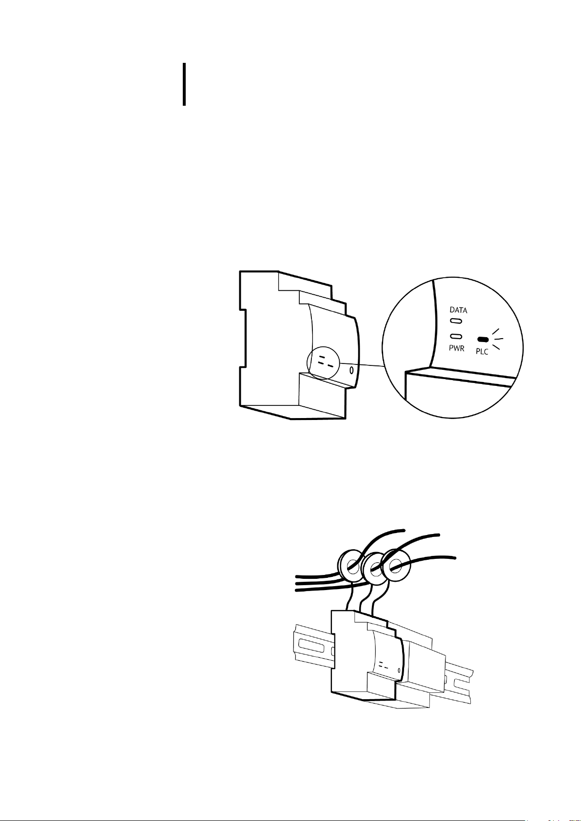
Figure 3: LED lights of Load Guard
The Load Guard has three LEDs on the front plate labelled PWR, DATA and
PLC. When the Load Guard is connected to the power supply, the PWR
light should light up. If the connection between the Load Guard and the
charging station is established, the DATA light flashes. If a PLC connection
is established, the PLC light should light up.
Figure 4: Measuring current transformers set on all three phases
5 | 24
Etrel Load Guard | User manual
|
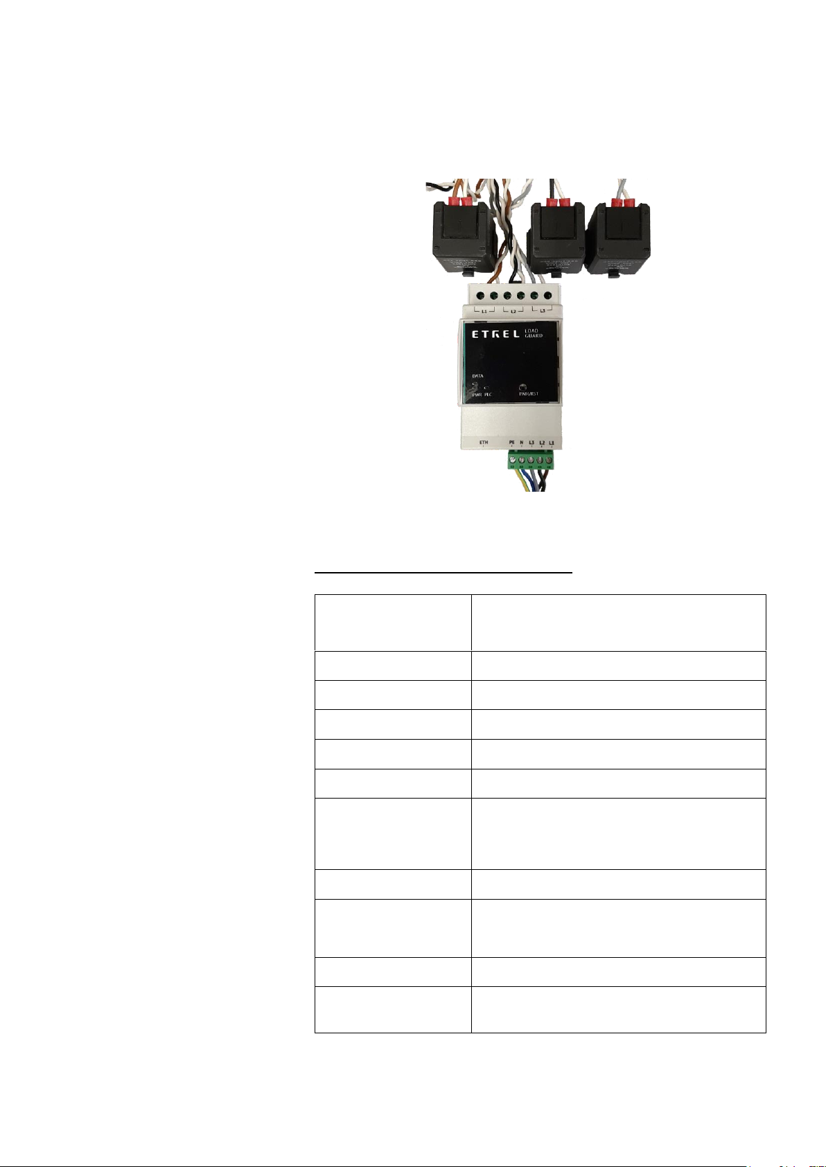
To measure electric current, it uses 150 A current clamps (for conductors
up to 16 mm in diameter) and 400 A current clamps (for conductors up to
24 mm in diameter). The length of the wires for connecting the current
clamps to the Load Guard is 70 cm.
Figure 5: Load Guard with connected measuring current transformers
TECHNICAL SPECIFICATIONS
DIMENSIONS
90.5 x 53.5 x 61.8 [mm]
Width 3 TE on DIN rail
WEIGHT
0.23 - 0.70 [kg], packaging adds 0.10 [kg]
CLAMP CABLE LENGTH
70 cm
CLAMP DIAMETER
Small 16 mm, large 24 mm
CONNECTION
Single-phase or three-phase
MAX. RATED CURRENT
150 A or 400 A per phase
OPERATING VOLTAGE
Up to 253 V AC phase voltage
This limitation is set by the highest operational voltage
of the charging station.
FREQUENCY
50 Hz or 60 Hz
TEMPERATURE RANGE
Operation temperature range: -25°C to +60°C
Storage temperature range: -30°C to +90°C
COMMUNICATION
Ethernet
CONFIGURATION AND
MONITORING
Web interface
6 | 24
Etrel Load Guard | User manual
|
3 CONNECTING THE LOAD GUARD
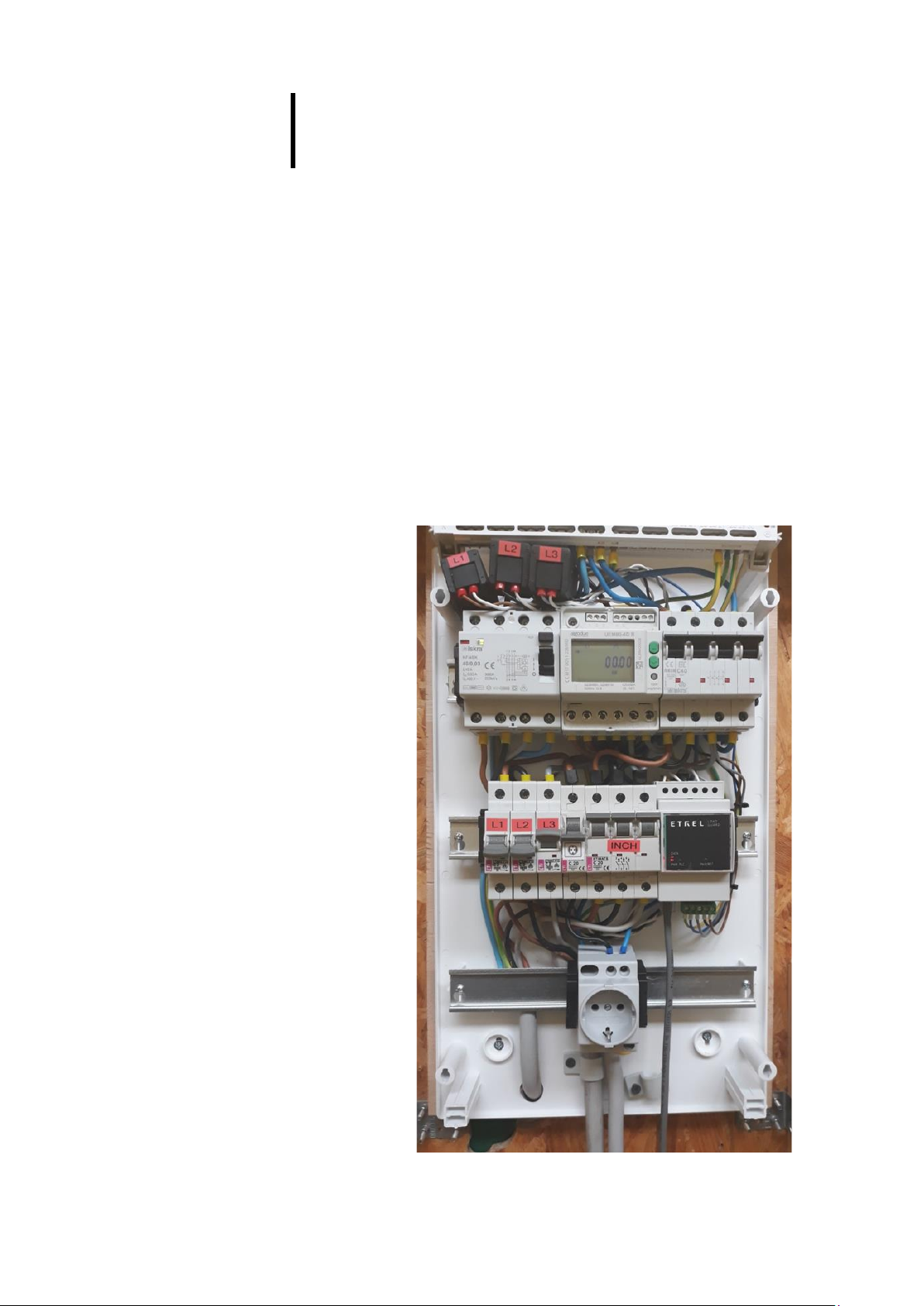
Load Guard is installed in electrical cabinet, after the main counter. It
measures currents of all phases and is sending the measurements to the
charging station in real time to ensure that the overload of the fuses
cannot happen.
It can measure in both directions, so it can also measure the energy that
is flowing back to the electrical grid. In case of production of energy at the
location it can turn up the charging power suppling the electric vehicle.
When bought at the same time, the Load Guard and charging station
would already be preconfigured and both devices would be already
paired.
Load Guard can be connected single-phase or three-phase. Current
clamps should be put on certain phase conductors and the Load Guard
should be properly connected to the power supply first and only then to
the LAN.
Figure 6: Load Guard installed in electrical cabinet
7 | 24
Etrel Load Guard | User manual
|
LOAD GUARD CURRENT TRANSFORMERS
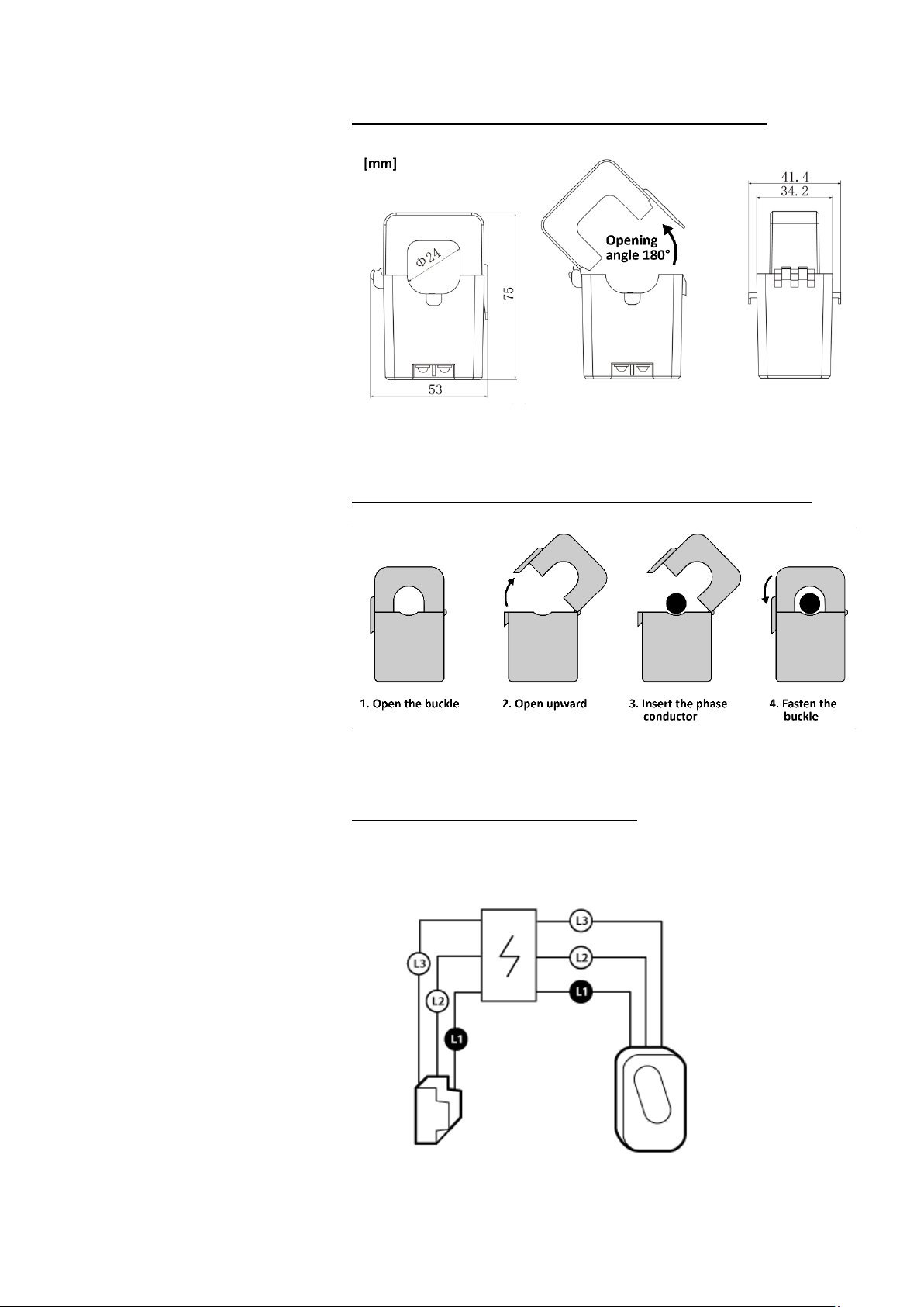
Figure 7: Dimensions of current transformers
CONNECTING THE CURRENT TRANSFORMERS
Figure 8: Connecting the current transformers
THREE-PHASE CONNECTION
For proper three-phase connection, current clamps must be placed on
specific phase conductors.
Figure 9: Correct connection must consider the correct sequence of phases

8 | 24
Etrel Load Guard | User manual
|
The following figure shows the current clamp cables connection for all
three phases (L1, L2 in L3) from left to right. The phase conductors for
powering the Load Guard must be connected in the same way (from right
to left). Positions for PE (earthing conductor) and N(neutral conductor)
are also indicated. If phases are not connected in correct sequence, the
Load Guard power calculation will be wrong.
Figure 10: Arrangement of input and output phases
Measuring current transformers are connected to the Load Guard as it is
shown on the following figure.
Figure 11: Load Guard and connected measuring current transformers
The procedure of setting up measuring current transformer on the
conductor is to open it and close it with conductor wire inside of it. The
conductor does not need to be interrupted for the connection.
L1
L2
L3
P
E
N
L
1
L
2
L
3

9 | 24
Etrel Load Guard | User manual
|
The direction of energy flow must be considered. On the inside of the
measuring current transformer there is an arrow, which must point in the
direction of energy flow (from clamps to the consumers). If the direction
of measuring current transformer is wrong, Load Guard will be measuring
negative power. If this happens, turn the measuring current transformer
correctly.
Figure 12: Arrow pointing in the direction of energy flow
SINGLE-PHASE CONNECTION
In case of single-phase connection, the measuring current transformer is
set only on the phase conductor that is used, as shown on the following
figure.
Figure 13: Single phase connection of measuring current transformer
Only one measuring current transformer is needed in single-phase
connection. Load Guard must be connected as shown in the following
figure.
If phase and neutral conductors are switched (L1 in N), the voltage in Load
Guard Configuration Software will be very low, or even 0 V (instead of
~230 V).
Consumptio
n
To
Load Guard
Cabinet
terminals

10 | 24
Etrel Load Guard | User manual
|
Figure 14: Arrangement of input and output phases in case of single-phase connection
PRODUCTION OF ENERGY AT THE LOCATION
If on location there is also production of electrical energy present
(photovoltaic cells, batteries, ...), the measuring current transformers can
be set on two conductors (production conductor and consumption
conductor). In this case the Load Guard would be measuring the
difference of consumption and production currents and would enable
higher charging current in time of production.
Figure 15: Measuring current transformer on two conductors
L
P
N
L
Consumpti
on
Production
To
Load
Cabinet
terminals
11 | 24
Etrel Load Guard | User manual
|
4 OBTAINING IP ADRESS OF COMPUTER AND
CHARGING STATION
To enable configuration of the Load Guard and of the charging station,
the computer, Load Guard and charging station need to be in the same
network segment: 192.168.1.xxx. First three numbers must be the same
and the fourth must be different among the devices.
COMPUTER IP ADDRESS
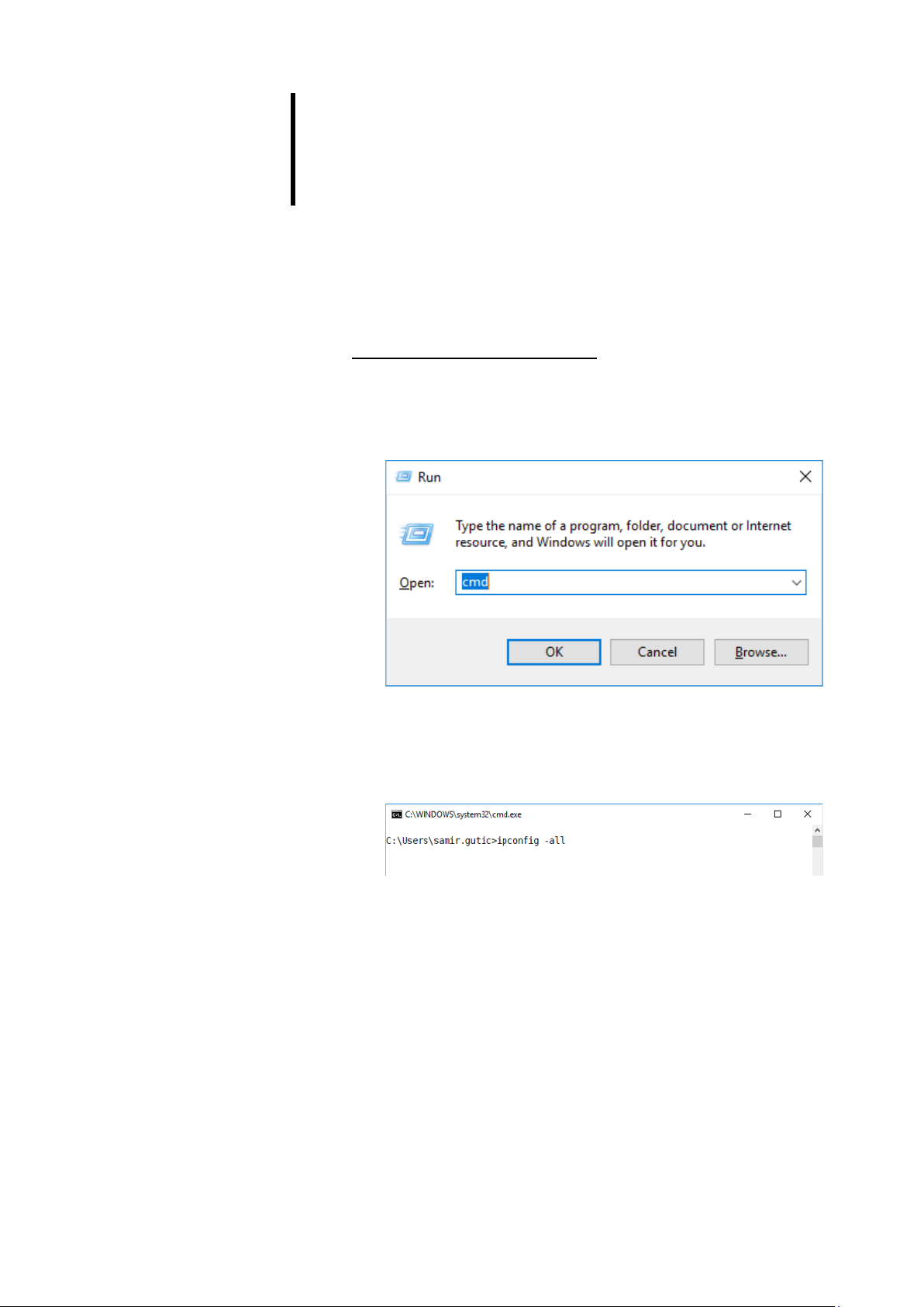
To obtain IP address of the computer the Windows Command Prompt is
used. Press Win+R on the keyboard and in the presented window type
cmd and press Enter (or click OK).
Figure 16: Starting the Command Prompt
Black Command Prompt windows will show and in it write command
ipconfig -all and press Enter (Note: between “ipconfig”and “-all” there is
a space).
Figure 17: Ipconfig command
The configuration of all network interfaces including Wi-Fi will be
displayed.

12 | 24
Etrel Load Guard | User manual
|
Figure 18: Display of configuration of all network interfaces of the computer
In the case presented in the above figure, the computer does not have
Wi-Fi module, and only options of wired interfaces are shown (ethernet).
The part of the IP address that is inside of red rectangle must be the same
as it is written in the Load Guard Configuration Software settings. If this is
not true, the software could not find the Load Guard and even if Load
Guard is found, the configuration is not possible.
CHARGING STATION IP ADDRESS
If the IP address of the charging station is not known, press the reset key
for 5 seconds (figure below).
Figure 19: Charging station reset button
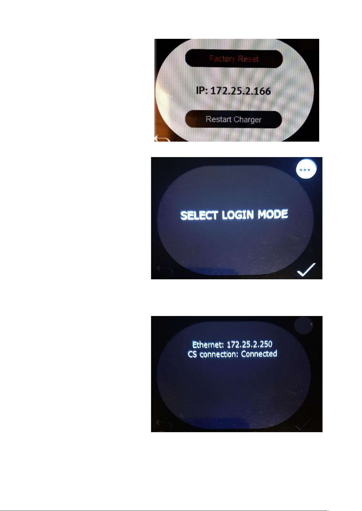
On the charging station display the message Entering service menu will
be shown and after that also the IP address. To obtain the charging station
IP address, press the sign of three dots for 5 s (in the upper right corner).
13 | 24
Etrel Load Guard | User manual
|
Figure 20: Display of IP address after pressing the reset button for 5 s
Figure 21: Selection of login mode
The IP address of the charging station and the state of the connection with
central system will be displayed.
Figure 22: Display of network and state
14 | 24
Etrel Load Guard | User manual
|
5 CONFIGURATION
SOFTWARE FOR CONFIGURATION
Configuration software Load Guard Configurator 1.4.zip can be
downloaded from the following address:
https://etrelchargingsolutions.atlassian.net/wiki/download/attachments
/258867203/Load Guard Configurator 1.4.zip?api=v2
Expand the compressed file in new folder Load Guard Configurator 1.4.
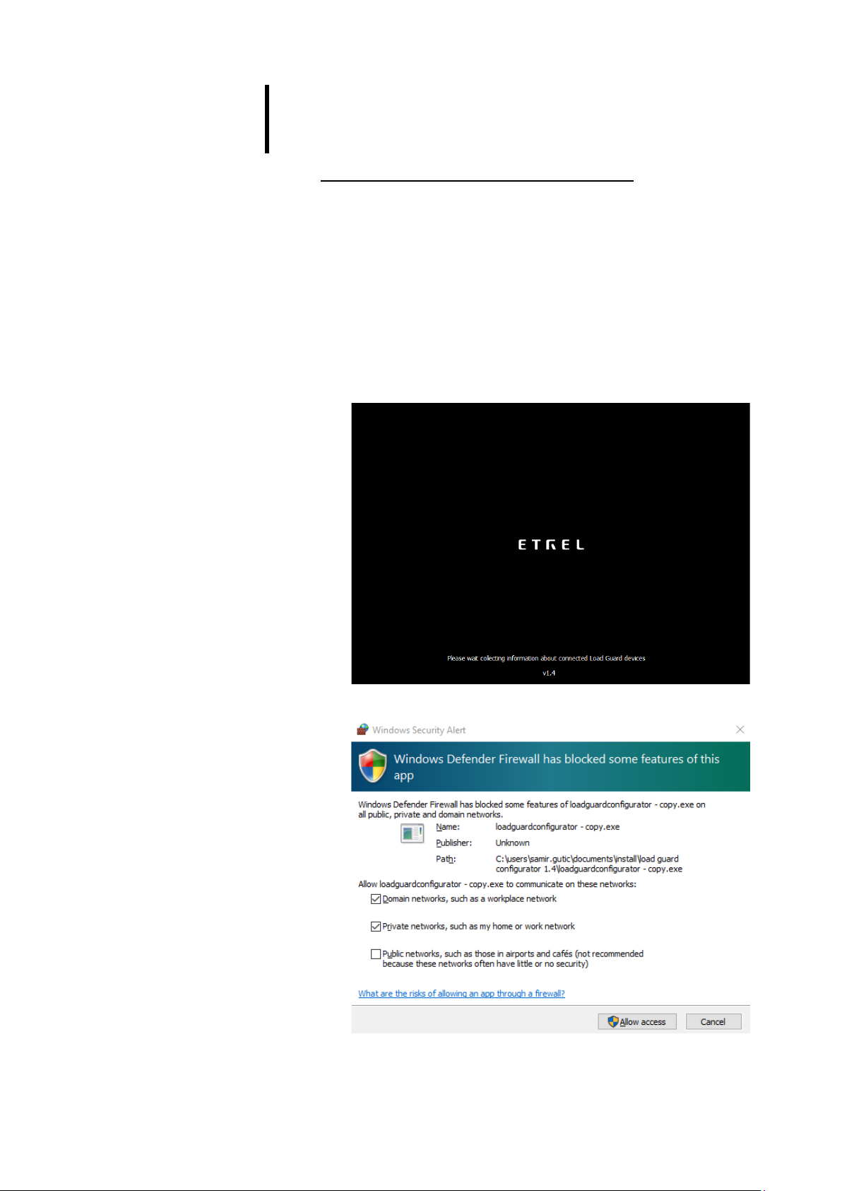
Click on LoadGuardConfigurator.exe inside the folder opens software for
configuration of Load Guard. The message of Windows Firewall will be
presented.
Figure 23: Starting configuration software
Figure 24: Message of Windows Firewall
15 | 24
Etrel Load Guard | User manual
|
Enable the access as shown on the previous figure. Then click on the Allow
access and enable the configuration of the Load Guard. If the software
finds the Load Guard in its network, the data of Load Guard will be
presented on the screen.
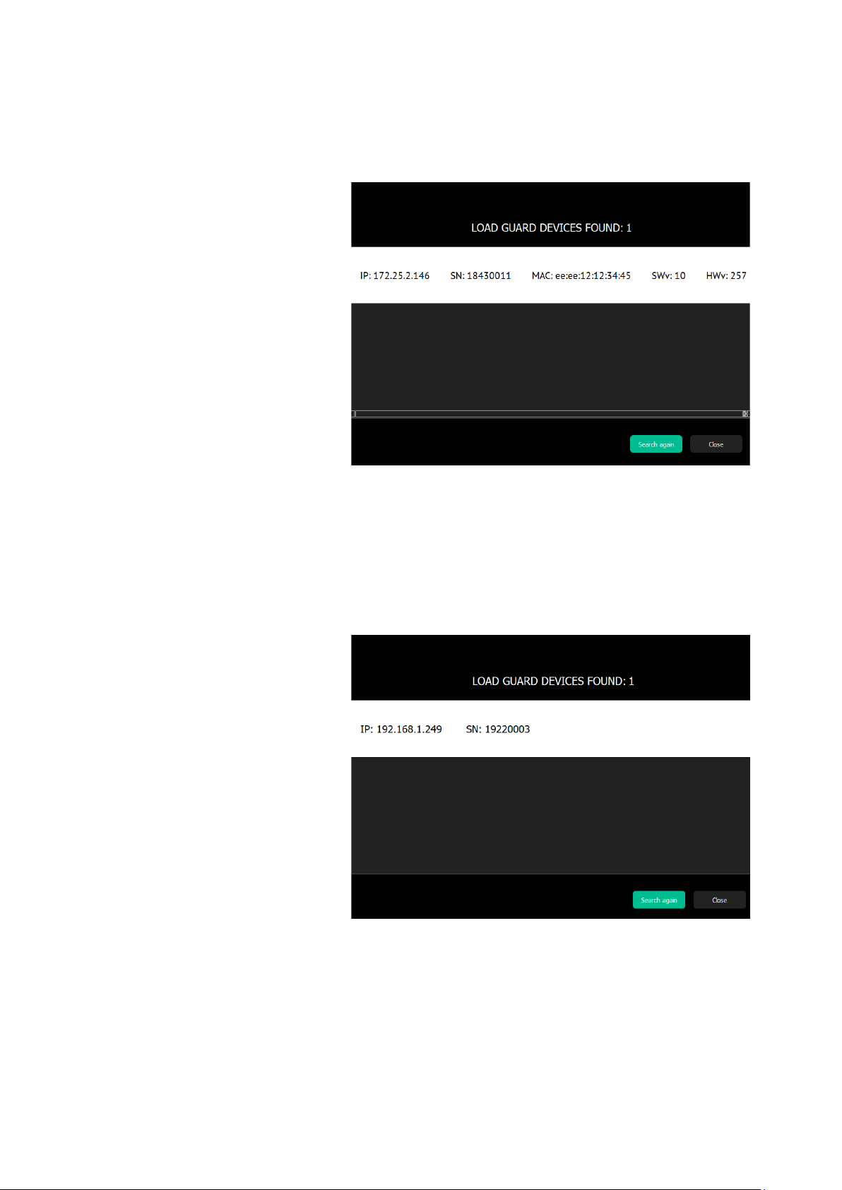
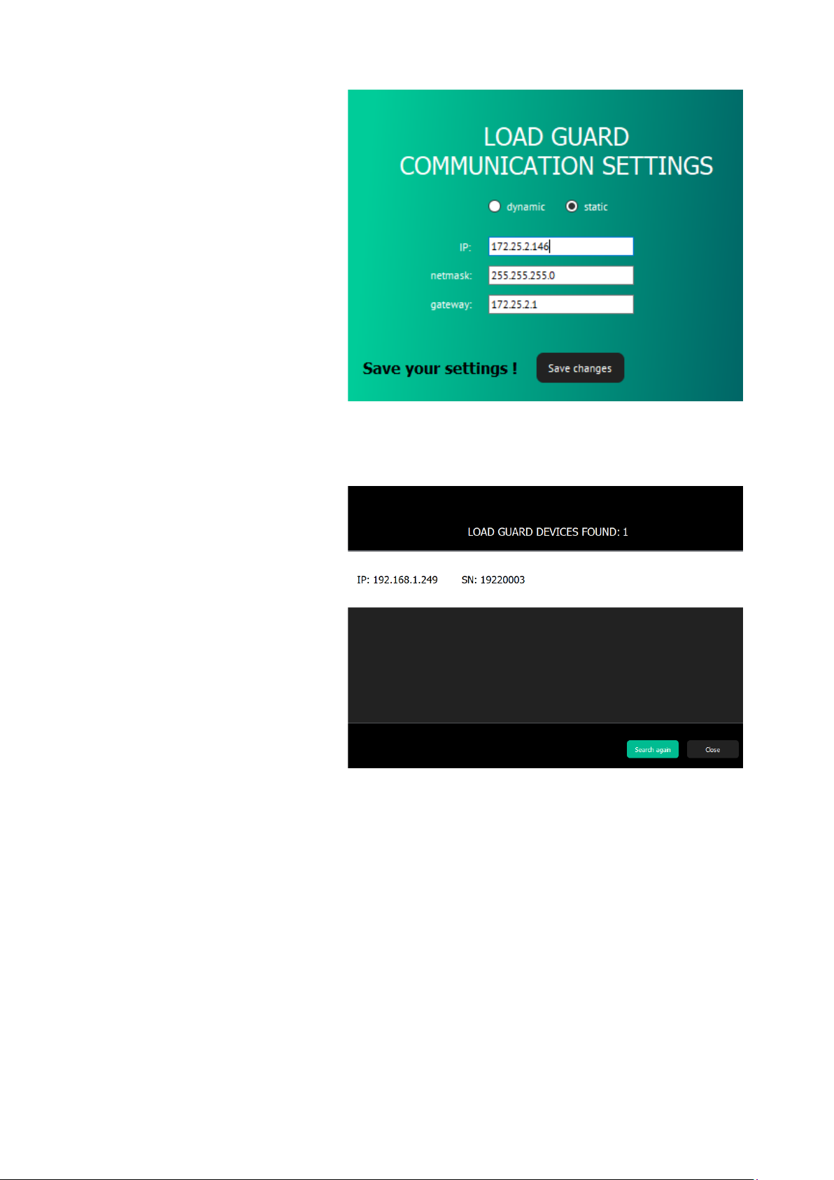
Figure 25: Display of Load Guard information
Load Guard serial number is important information. In the above case it
is 18430011. For establishing connection this serial number must be listed
in charging station web interface. Click on the white part of the screen
(the line with Load Guard data) opens the configuration window. If the
software finds Load Guard and the MAC address is not shown, this means
that the computer is not in the same network as Load Guard.
Figure 26: MAC is not shown –the computer is not in the same network

16 | 24
Etrel Load Guard | User manual
|
CONFIGURATION OF THE LOAD GUARD
To configure Load Guard, the following is needed:
•IP address of the charging station that is used to connect Load
Guard to.
•Serial number of the charging station that is used to connect Load
Guard to.
LOAD GUARD NETWORK SETTINGS
Click on the white part of the screen (the line with Load Guard data) opens
the configuration window.
Figure 27: Windows for configuration settings
Default IP address of the Load Guard is 192.168.1.249.
If the measured data are presented in a same way as on the above figure
(currents, powers, voltages, times ...) it means that the Load Guard
Configurator software successfully connected to the Load Guard.
If the time on the Load Guard is wrong, the time synchronization must be
performed with the click on Sync device time, otherwise the connection
will not be functional. After that the settings are saved with a click on Save
changes (bottom right).
Charging station can be connected in LAN network in two ways, statically
or dynamically. If there is DHCP server present in the network, the
dynamic option can be selected in Load Guard communication settings.
Otherwise the Static option must be selected. Settings are displayed in
the following figure.
17 | 24
Etrel Load Guard | User manual
|
Figure 28: Static connection data entry
For saving of changes, click on Save changes. After that the Load Guard
will reset automatically.
Figure 29: Load Guard is not in the same network group as computer
If the IP address of the Load Guard was changed in a way that the Load
Guard is not part of the same network group as the computer anymore
(e.g. switching of one of the first three numbers of the IP address), only
the IP address and serial number of the Load Guard will be displayed.
In this case the IP address of the computer should be changed accordingly,
so that the first three numbers of the IP address are the same as on Load
Guard.
When purchasing Load Guard together with charging station, they are
already set and tested at the factory and already configured for automatic
pairing of both devices.

18 | 24
Etrel Load Guard | User manual
|
CHARGING STATION SERIAL NUMBER
Serial number of charging station can be found in charging station web
interface. After the login to the web interface Diagnostics must be
selected in Etrel menu. The serial number of the charging station will be
displayed as shown on the below figure:
Figure 30: Display of basic data in Diagnostics menu
We are interested in the number: 18010000, which is a serial number of
charging station.
PAIRING
PAIRING OF LOAD GUARD TO CHARGING STATION
When all the needed information are available, the configuration of Load
Guard can continue. In IP address field the IP address of the charging
station must be written, also in the Serial field, the serial number of the
charging station must be written. Serial number of the charging station
can be obtained from the web interface of the charging station.
Correct IP address must be written, which is in the given case
172.25.2.250 and the serial number, which is in the given case 18310069.
After that the changes are saved with click on Save changes.
If everything is set correctly, the message about the successful connection
will be shown (Connection established).
Figure 31: Connection with charging station established
If wrong serial number is set, the message would be: Connection broken.
19 | 24
Etrel Load Guard | User manual
|
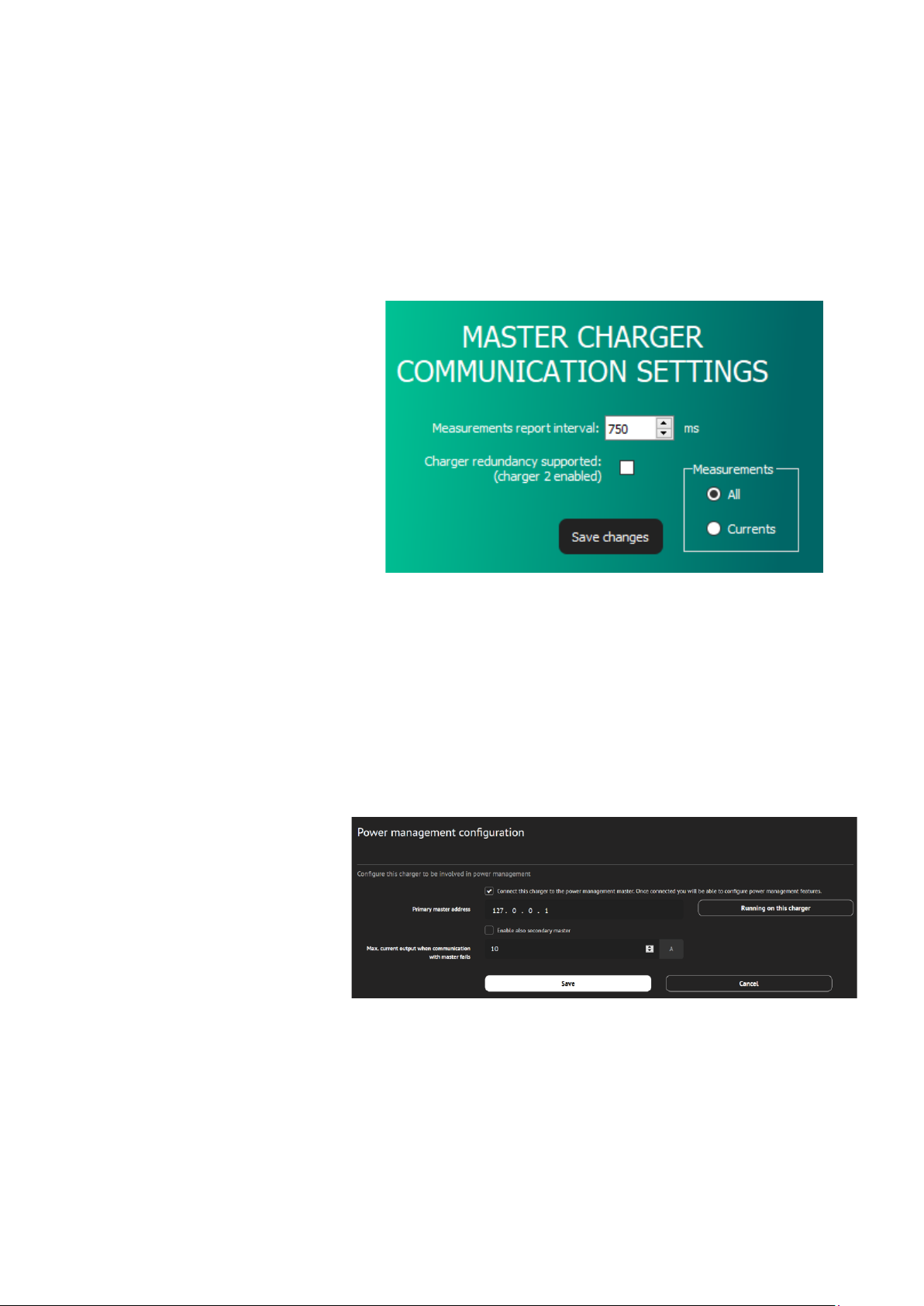
The interval of measured data transmission can be set –Mesurements
report interval. The time interval can be set between values 500 ms and
5000 ms (default setting is 750 ms).
In the Measurements window it is selected which data will be Load Guard
sending to the charging station. To send all the data, the option All must
be selected. If this is not set, the charging station will ignore some of the
data that Load Guard is sending. Confirm the setting with click on Save
changes.
Figure 32: Setting the measurement report interval
PAIRING OF CHARGING STATION WITH LOAD GUARD
To connect to INCH charging station web interface use username:
In web configuration interface select Power management and then
General Configuration. Make sure that the tick “Connect this charger to
the power management master” is selected.
Figure 33: Power management configuration
In the web configuration interface select Power management and then
Power cluster configuration. Select the tick at “Enable cluster service”.
Table of contents
Popular Accessories manuals by other brands


Tempest
Tempest 400 quick start guide

Surpass
Surpass HASP-SHT2 Operation manual

S+S Regeltechnik
S+S Regeltechnik AERASGARD KLQ Operating Instructions, Mounting & Installation

Dataradio
Dataradio Paragon4 user manual

Elsner
Elsner KNX T-UP gl Installation and adjustment

Miscea
Miscea "Classic" instruction manual


