ETS-Lindgren MACS/D Series User manual
Magnetic Active
Compensation System (MACS)
MACS/D Series Digital Signal Processor-Based
User Manual
1680736 Rev CFebruary 2019


3
ETS-Lindgren Inc. reserves the right to make changes to any products herein to improve functioning or design.
Although the information in this document has been carefully reviewed and is believed to be reliable, ETS-Lindgren
does not assume any liability arising out of the application or use of any product or circuit described herein; nor does
it convey any license under its patent rights nor the rights of others. All trademarks are the property of their respective
owners.
© Copyright 2019 by ETS-Lindgren Inc. All Rights Reserved. No part of this document may be copied by any
means without written permission from ETS-Lindgren Inc.
Trademarks used in this document: The ETS-Lindgren logo is a registered trademark of ETS-Lindgren, Inc.
Revision Record
MANUAL, PRODUCT NAME | Part # 1680736 Rev C
Revision Description Date
AInitial Release May, 2018
BUpdates to connector information January, 2019
CSection A.2.3 updated February, 2019

4

5
TABLE OF CONTENTS
NOTES, CAUTIONS AND WARNINGS 9
SAFETY INFORMATION 9
GENERAL SAFETY CONSIDERATIONS 10
1 OPERATORS SAFETY SUMMARY 11
1.1 CONFORMANCE TO INDUSTRY STANDARDS . . . . . . . . . . . . . . . . . 11
1.1.1 Safety . . . . . . . . . . . . . . . . . . . . . . . . . . . . . . . 11
1.1.2 Regulatory Requirements . . . . . . . . . . . . . . . . . . . . . . . . 11
1.2 TERMS . . . . . . . . . . . . . . . . . . . . . . . . . . . . . . . . . 11
1.2.1 In This Manual . . . . . . . . . . . . . . . . . . . . . . . . . . . . 11
1.2.2 As Marked on Equipment . . . . . . . . . . . . . . . . . . . . . . . . 11
1.3 SYMBOLS . . . . . . . . . . . . . . . . . . . . . . . . . . . . . . . 11
1.3.1 In This Manual . . . . . . . . . . . . . . . . . . . . . . . . . . . . 11
1.3.2 Symbols as Marked on Equipment . . . . . . . . . . . . . . . . . . . . 11
1.4 POWER . . . . . . . . . . . . . . . . . . . . . . . . . . . . . . . . 12
1.4.1 Power Source . . . . . . . . . . . . . . . . . . . . . . . . . . . . 12
1.4.2 Grounding the Product . . . . . . . . . . . . . . . . . . . . . . . . . 12
1.4.3 Danger Arising From Loss of Ground . . . . . . . . . . . . . . . . . . . 12
1.4.4 Use the Proper Power Cord . . . . . . . . . . . . . . . . . . . . . . . 12
1.4.5 Do Not Operate in Explosive Atmospheres . . . . . . . . . . . . . . . . . 13
1.4.6 Do Not Remove Covers or Panels . . . . . . . . . . . . . . . . . . . . 13
2 SERVICING SAFETY SUMMARY 15
2.1 DO NOT SERVICE ALONE . . . . . . . . . . . . . . . . . . . . . . . . . 15
2.2 USE CARE WHEN SERVICING WITH POWER ON . . . . . . . . . . . . . . . 15
2.3 POWER SOURCE . . . . . . . . . . . . . . . . . . . . . . . . . . . . 15
3 SYSTEM DESCRIPTION 17
3.1 INTRODUCTION . . . . . . . . . . . . . . . . . . . . . . . . . . . . . 17
3.2 OVERVIEW AND SYSTEM COMPONENTS . . . . . . . . . . . . . . . . . . 19
3.2.1 System Controller (MXA) . . . . . . . . . . . . . . . . . . . . . . . . 19
3.2.2 Coil Driver Amplier (CDA) . . . . . . . . . . . . . . . . . . . . . . . 19
3.2.3 Magnetic Field Sensor . . . . . . . . . . . . . . . . . . . . . . . . . 20
3.2.4 Compensation Coils . . . . . . . . . . . . . . . . . . . . . . . . . . 20
3.3 SYSTEM CONTROLS, CONNECTORS AND INDICATORS 21
3.3.1 Controller Front Panel . . . . . . . . . . . . . . . . . . . . . . . . . 21

6
3.3.2 Controller Rear Panel . . . . . . . . . . . . . . . . . . . . . . . . . 22
3.3.3 System Controller Main PCB Coil Resistance Jumpers 24
3.3.4 Coil Driver Amplier . . . . . . . . . . . . . . . . . . . . . . . . . . 25
4 HTML USER AND DEVELOPMENT INTERFACE 27
4.1 TOP LEVEL MENU PAGE . . . . . . . . . . . . . . . . . . . . . . . . . 27
4.2 MACHINE PERFORMANCE TRACES PAGE . . . . . . . . . . . . . . . . . . 27
4.2.1 Examine a Trace . . . . . . . . . . . . . . . . . . . . . . . . . . . 28
4.3 DSP Capture Page . . . . . . . . . . . . . . . . . . . . . . . . . . . 30
4.4 DSP PARAMETERS PAGE . . . . . . . . . . . . . . . . . . . . . . . . . 31
4.5 LOCAL LOGIN AND VPN SECURE REMOTE ACCESS 35
4.5.1 Local Internet or LAN Ethernet Connection . . . . . . . . . . . . . . . . . 35
4.5.2 Remote Access to Internet for MACS/D Systems - VPN Setup 35
4.5.3 MAC Address. . . . . . . . . . . . . . . . . . . . . . . . . . . . . 35
5 INSTALLATION 37
5.1 SYSTEM LAYOUT . . . . . . . . . . . . . . . . . . . . . . . . . . . .37
5.1.1 Magnetic Field Sensor Location and Installation . . . . . . . . . . . . . . . 37
5.1.2 MACS/D Rack Cabinet Location . . . . . . . . . . . . . . . . . . . . . 38
5.1.3 Compensation Coil Installation . . . . . . . . . . . . . . . . . . . . . . 38
5.1.4 Compensation Coil Connections to the Rear Interface Panel 40
5.2 SYSTEM FINAL INSTALLATION . . . . . . . . . . . . . . . . . . . . . . . 41
5.2.1 Initial Onsite Verications . . . . . . . . . . . . . . . . . . . . . . . . 41
5.2.2 Onsite Setups and Electrical Interconnects . . . . . . . . . . . . . . . . . 42
5.2.3 Setup Using the WEB UI . . . . . . . . . . . . . . . . . . . . . . . . 43
5.3 FIELD COMPENSATION ADJUSTMENT AND VERIFICATION 44
5.3.1 Setting the Axis Polarity and Gains (MEA and MRI): 44
5.3.2 ACR Setup: . . . . . . . . . . . . . . . . . . . . . . . . . . . . .44
5.4 AMPLIFIER CURRENT CHECK AND ATTENUATION FACTOR CHECKS 45
5.4.1 Amplier Current Check: . . . . . . . . . . . . . . . . . . . . . . . . 45
5.4.2 Attenuation Factor Checks: . . . . . . . . . . . . . . . . . . . . . . . 45
5.4.3 Chime Loudness Adjustment: . . . . . . . . . . . . . . . . . . . . . . 45
6 OPERATION 47
6.1 GENERAL COMMENTS . . . . . . . . . . . . . . . . . . . . . . . . . . 47
6.2 POWER-UP SEQUENCE . . . . . . . . . . . . . . . . . . . . . . . . . . 47
6.2.1 Baseline Acquisition: . . . . . . . . . . . . . . . . . . . . . . . . . . 47
6.2.2 Power/Level Trip and Reset: . . . . . . . . . . . . . . . . . . . . . . . 47
6.3 MACS/D CONTROLLER OPERATIONAL STATES . . . . . . . . . . . . . . . . 48

7
6.3.1 Acquire . . . . . . . . . . . . . . . . . . . . . . . . . . . . . . . 49
6.3.2 Setup . . . . . . . . . . . . . . . . . . . . . . . . . . . . . . . . 49
6.3.3 Operate . . . . . . . . . . . . . . . . . . . . . . . . . . . . . . . 50
6.3.4 Overlevel . . . . . . . . . . . . . . . . . . . . . . . . . . . . . . 50
6.3.5 Disabled . . . . . . . . . . . . . . . . . . . . . . . . . . . . . . 50
6.4 USING THE WEB UI. . . . . . . . . . . . . . . . . . . . . . . . . . . . 50
7 GENERAL COMMENTS 51
7.1 SCHEDULED INSPECTIONS . . . . . . . . . . . . . . . . . . . . . . . . 51
7.2 INDICATIONS FOR RE-CALIBRATION . . . . . . . . . . . . . . . . . . . . 51
7.3 RE-CALIBRATION . . . . . . . . . . . . . . . . . . . . . . . . . . . . 51
7.4 PROBE REPOSITION . . . . . . . . . . . . . . . . . . . . . . . . . . . 51
7.5 COIL(S) REPOSITION . . . . . . . . . . . . . . . . . . . . . . . . . . . 51
7.6 SUBSYSTEM REPAIR OR REPLACEMENT . . . . . . . . . . . . . . . . . . 51
7.7 PROBE . . . . . . . . . . . . . . . . . . . . . . . . . . . . . . . . . 51
7.8 MACS/D RACK CABINET . . . . . . . . . . . . . . . . . . . . . . . . . 52
7.9 COIL DRIVER AMPLIFIER (CDA) . . . . . . . . . . . . . . . . . . . . . . 52
APPENDICES 53
A.1 BARTINGTON PROBE SPECIFICATIONS . . . . . . . . . . . . . . . . . . . 53
Bartington MAG-03MCT-series . . . . . . . . . . . . . . . . . . . . . . . . 53
Bartington MAG-03MCT1000 . . . . . . . . . . . . . . . . . . . . . . . . . 53
Bartington MAG639 (Reserved) . . . . . . . . . . . . . . . . . . . . . . . . 53
A.2.1 SUBSYSTEMS - MACS/D CONTROLLER (MXA) 54
A.2.2 SUBSYSTEMS - COIL DRIVER AMPLIFIER (CDA) . . . . . . . . . . . . . . . 54
A.2.3 MACS/D SYSTEM ASSEMBLED IN RACK CHASSIS SPECIFICATIONS 54
A.3 CONTROLLER STATE FLOWCHART . . . . . . . . . . . . . . . . . . . . . 55
A.4 ETS-LINDGREN WORLDWIDE CONTACT INFORMATION 56

8

9
NOTES, CAUTIONS AND WARNINGS
Note: Denotes helpful information intended to provide tips for better use of
the product.
Caution: Denotes a hazard. Failure to follow instructions could result in
minor personal injury and/or property damage. Included text gives proper
procedures.
Warning: Denotes a hazard. Failure to follow instructions could result in
SEVERE personal injury and/or property damage. Included text gives proper
procedures.
SAFETY INFORMATION
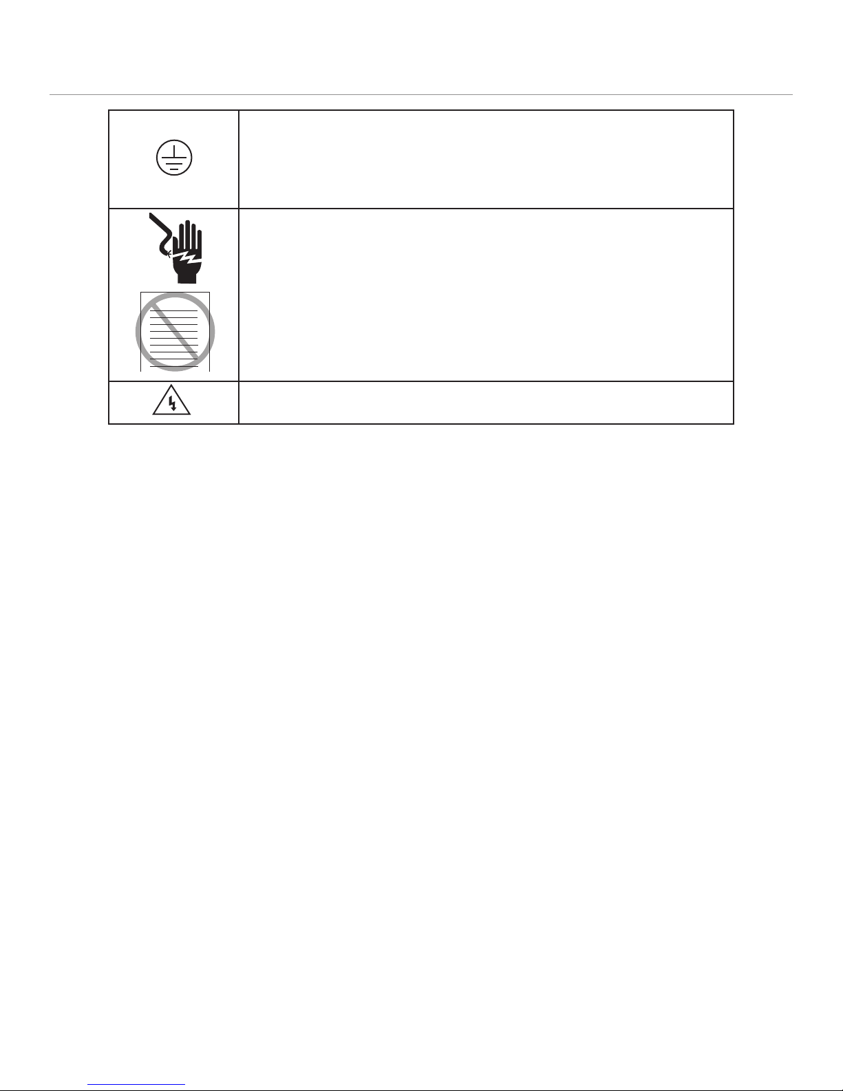
Refer to Manual: When product is marked with this symbol, see the
instruction manual for additional information. If the instruction manual has
been misplaced, download it from ets-lindgren.com, or contact ETS-Lindgren
Customer Service.
High Voltage: Indicates presence of hazardous voltage. Unsafe practice
could result in severe personal injury or death.
High Voltage: Indicates presence of hazardous voltage. Unsafe practice
could result in severe personal injury or death.
Protective Earth Ground (Safety Ground): Indicates protective earth
terminal. You should provide uninterruptible safety earth ground from the
main power source to the product input wiring terminals, power cord, or
supplied power cord set.
See the ETS-Lindgren Product Information Bulletin for safety, regulatory, and other product marking
information.
10
GENERAL SAFETY CONSIDERATIONS
Before power is applied to this instrument, ground it properly through the
protective conductor of the AC power cable to a power source provided with
the protective earth contact. Any interruption of the protective (grounding)
conductor, inside or outside the instrument, or disconnection of the protective
earth terminal could result in personal injury.
Before servicing: contact ETS-Lindgren – servicing (or modifying) the unit by
yourself may void your warranty. If you attempt to service the unit by yourself,
disconnect all electrical power before starting. There are voltages at many
points in the instrument which could, if contacted, cause personal injury.
Only trained service personnel should perform adjustments and/or service
procedures upon this instrument. Capacitors inside this instrument may still
be CHARGED even when instrument is disconnected from its power source.
Only qualied personnel should operate (or service) this equipment.
WARRANTY

11
1 OPERATORS SAFETY SUMMARY
The general safety information in this part of the summary is for both operating and servicing personnel. Specic
warnings and cautions will be found throughout the manual where they apply.
1.1 CONFORMANCE TO INDUSTRY STANDARDS
This instrument complies with the following industry safety standards and regulatory requirements.
1.1.1 Safety
CSA: Electrical Bulletin
FM: Electrical Utilization Standard Class 3820
ANSI C39.5 — Safety Requirements for Electrical and Electronic Measuring and Controlling Instrumentation
1.1.2 Regulatory Requirements
VDE 0871 Class B — Regulations for RFI Suppression of High Frequency Apparatus and Installations.
1.2 TERMS
1.2.1 In This Manual
CAUTION statements identify conditions or practices that could result in damage to the equipment or other
property.
WARNING statements identify conditions or practices that could result in personal injury or loss of life.
1.2.2 As Marked on Equipment
CAUTION indicates a personal injury hazard not immediately accessible as one reads the markings, or a hazard
to property, including the equipment itself.
DANGER indicates a personal injury hazard immediately accessible as one reads the marking.
1.3 SYMBOLS
1.3.1 In This Manual
This symbol indicates where applicable cautionary or other information is found.
The CAUTION sign denotes a hazard. It calls attention to an operating procedure, practice, or the like,
which, if not correctly performed or adhered to, could result in damage or destruction of part or all of the
equipment. Do not proceed beyond a CAUTION sign until the indicated conditions are fully understood
and met.
1.3.2 Symbols as Marked on Equipment
ATTENTION — Refer to manual for specic instruction in order to protect the instrument against damage.
12
Indicates dangerous voltages.
Earth terminal, ground.
1.4 POWER
1.4.1 Power Source
This product is intended to operate from a power source of either 100/120 volts 50/60 hertz that does not apply
more than 130 volts RMS, or 220/240 volts 50/60 hertz that does not apply more than 260 volts RMS between the
supply conductors, or between either supply conductor and ground. A protective ground connection by way of the
grounding conductor in the power cord is essential for safe operation.
1.4.2 Grounding the Product
This product is grounded through the grounding conductor of the power cord. A protective ground connection by
way of the grounding conductor in the power cord is essential for safe operation.
1.4.3 Danger Arising From Loss of Ground
Upon loss of the protective-ground connection, all accessible conductive parts (including knobs and controls that
may appear to be insulating) can render an electrical shock.
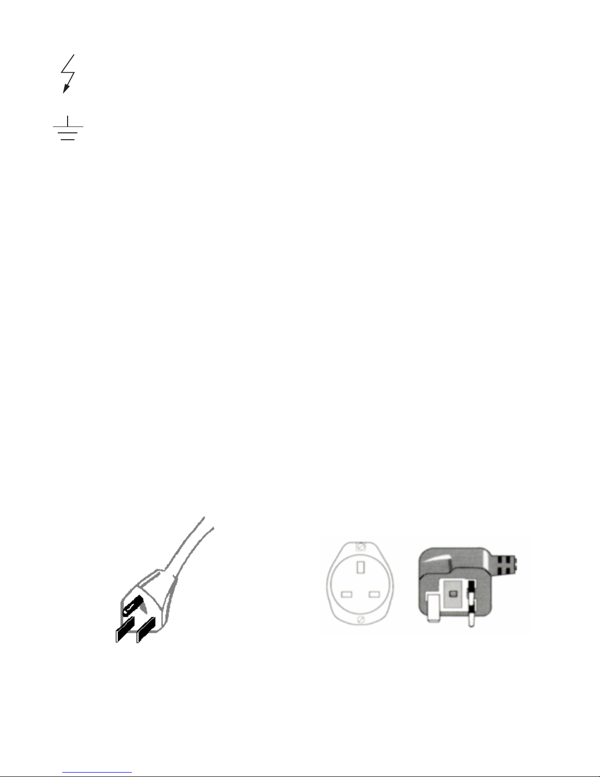
1.4.4 Use the Proper Power Cord
Use only the power cord and connector specied for your product.
Use only a power cord that is in good condition.
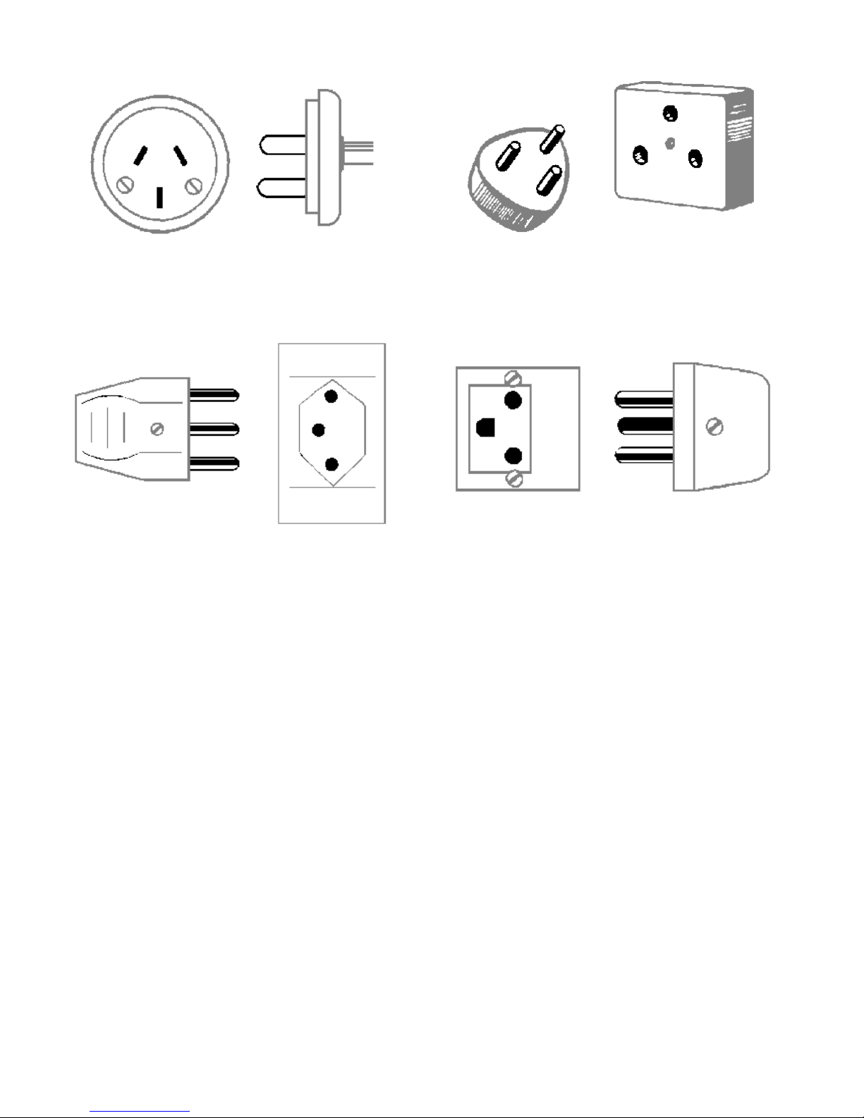
For detailed information on power cords and connectors, see Table 1 below.
North/South America/Japan
2 blade w/ground pin
120V
Britain/Ireland/Africa/Asia/India
2 blades rectangular ground blade
230V
Australia/China/New Zealand/Argentina
3 blade
240V
Israeli 3-pin/blade
220V
Swiss 3-pin
22V
Danish 3-pin
220V
Table 1. International Power Connector/Voltage Identication
13
1.4.5 Do Not Operate in Explosive Atmospheres
This product is not certied for operation in an explosive atmosphere.
1.4.6 Do Not Remove Covers or Panels
To avoid personal injury, do not remove the product covers or panels unless qualied to do so. Do not operate
the product, except for installation setup calibration by qualied personnel, or place this product in permanent
operation without the covers and panels properly installed.
Indicates dangerous voltages.
Earth terminal, ground.
1.4 POWER
1.4.1 Power Source
This product is intended to operate from a power source of either 100/120 volts 50/60 hertz that does not apply
more than 130 volts RMS, or 220/240 volts 50/60 hertz that does not apply more than 260 volts RMS between the
supply conductors, or between either supply conductor and ground. A protective ground connection by way of the
grounding conductor in the power cord is essential for safe operation.
1.4.2 Grounding the Product
This product is grounded through the grounding conductor of the power cord. A protective ground connection by
way of the grounding conductor in the power cord is essential for safe operation.
1.4.3 Danger Arising From Loss of Ground
Upon loss of the protective-ground connection, all accessible conductive parts (including knobs and controls that
may appear to be insulating) can render an electrical shock.
1.4.4 Use the Proper Power Cord
Use only the power cord and connector specied for your product.
Use only a power cord that is in good condition.
For detailed information on power cords and connectors, see Table 1 below.
North/South America/Japan
2 blade w/ground pin
120V
Britain/Ireland/Africa/Asia/India
2 blades rectangular ground blade
230V
Australia/China/New Zealand/Argentina
3 blade
240V
Israeli 3-pin/blade
220V
Swiss 3-pin
22V
Danish 3-pin
220V
Table 1. International Power Connector/Voltage Identication

14

15
2 SERVICING SAFETY SUMMARY
SERVICING INFORMATION FOR QUALIFIED SERVICE PERSONNEL ONLY
Refer also to the preceding Operators Safety Summary.
2.1 DO NOT SERVICE ALONE
Any internal adjustment, maintenance, and repair of the opened instrument under voltage should be carried out only
by a skilled person who is aware of the hazard involved.
It is recommended that internal service or adjustment of this product only be performed when another person
capable of rendering rst aid and resuscitation is present.
Do not install substitute parts or perform any unauthorized modication to the instrument.
2.2 USE CARE WHEN SERVICING WITH POWER ON
Dangerous A.C. mains voltages exist at several internal points in this product. To avoid personal injury, do not touch
exposed primary circuit connections or components while power is on.
Disconnect power before removing protective panels, soldering, or replacing components.
2.3 POWER SOURCE
This product is intended to operate from a power source of either 100/120 volts 50/60 hertz that does not apply more
than 130 volts RMS, or 220/240 volts 50/60 hertz that does not apply more than 260 volts RMS between the supply
conductors, or between either supply conductor and ground. A protective ground connection by way of the grounding
conductor in the power cord is essential for safe operation.
Prior to calibration or service requiring powered operation, verify that a protective electrical ground connection exists
by way of the grounding conductor in the power cord.

16
17
3 SYSTEM DESCRIPTION
3.1 INTRODUCTION
ETS-Lindgren MACS/D-ACR (Magnetic Active Compensation Shielding/Digital–Adjustable Compensation Ratio)
systems are designed to signicantly attenuate environmental magnetic elds affecting TEM, STEM, MRI, or other
magnetically-sensitive instrumentation or equipment. All MACS/D signal conditioning is performed in the digital
domain by the system’s high resolution, low-latency digital signal processor (DSP), which permits exacting denition
of the extremely accurate lter characteristics required for ACR processing. Unlike non-ACR compensation systems,
MRI application MACS/D-ACR systems are capable of attenuating interference with a ratiometric offset that provides
exceptional attenuation within the MRI magnet isocenter.¹ Further, specic MRI magnet modeling data may be
incorporated in MACS/D-ACR system to provide an additional measure of isocenter interference cancellation
improvement. For EMFC applications, the digital processor provides additional free-space compensation within the
Protected Volume (PV), while ACR capability permits optional offsetting of the point of optimal eld cancellation when
interfering signal gradient or gradients are signicant. Firmware-based signal conditioning also allows modication
of the signal processing when necessary for addressing specic site issues. To aid in on-site setup, the DSP engine
also permits rmware-based diagnostics via the MACS/D system for rapid evaluation of installation status and
parameters such as axial coil polarities, excitation efciency, and axial cross-coupling terms.
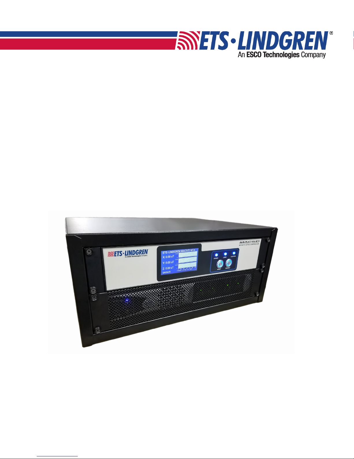
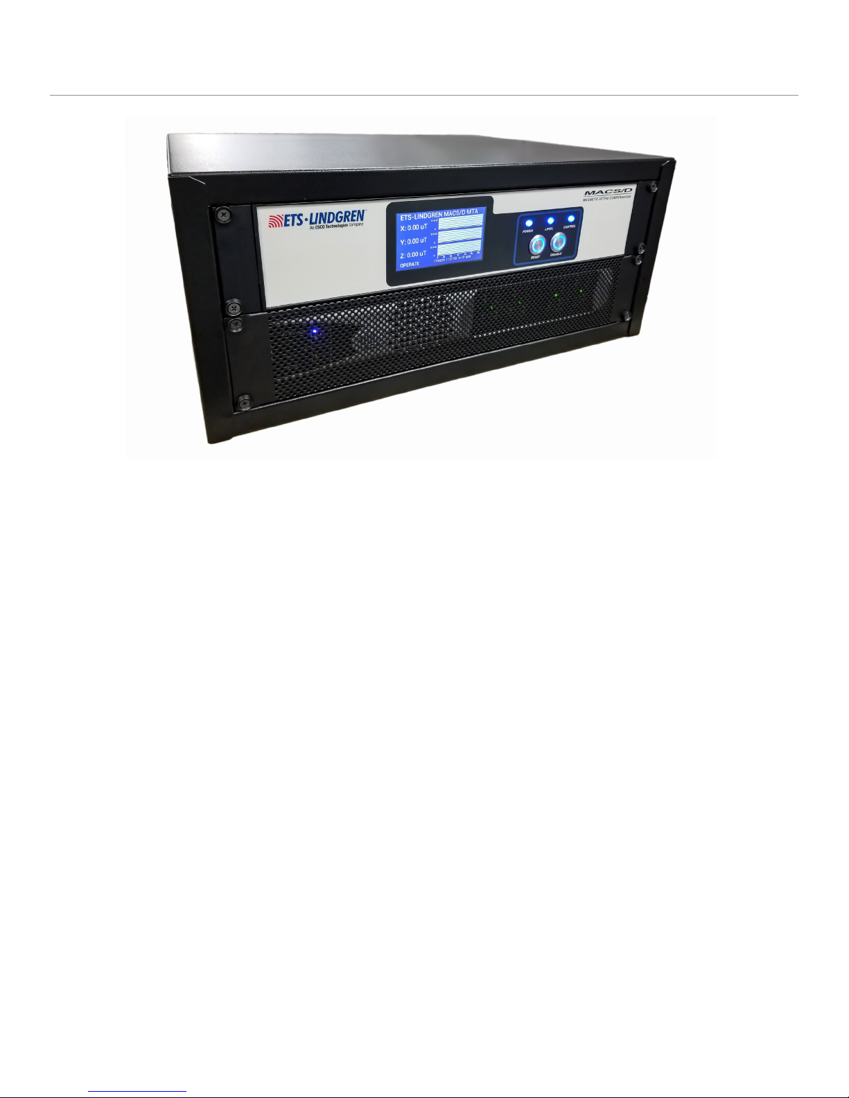
Figure 1. ETS-Lindgren MACS/D digital active compensation system (probe, coils not shown)
¹ Described in U.S. Patent No. 9,692,391 B2, "Adjustable Compensation Ratio Feedback System".

18
Denitions:
• MXA – MACS/D Controller/Signal Processor
• ADC – Analog to Digital Converter
• DSP – Digital Signal Processor
• DAC – Digital to Analog Converter
• CDA – Coil Driver Amplier
For MACS/D active compensation system installations, Operational Volume (OV) is dened as the space contained
within the orthogonal coil sets. Protected Volume (PV) is dened as the volume within the OV meeting the specied
site magnetic eld reduction coefcient.
As illustrated schematically in the block diagram of Figure 2, cancellation of unwanted environmental magnetic
eld variations is achieved by applying the canonic principle of negative feedback separately for each orthogonal
axis. Salient characteristics of the wideband negative feedback approach employed in the MACS/D system are
simultaneous compensation of all interference frequency spectra appearing within the MACS/D system’s passband
(approximately 1mHz – 500 Hz congured with standard probe, extended high-frequency options available) and
constant attenuation coefcient for any interference spectra within the system passband. Constant attenuation
applies, regardless of spectral amplitude, for the wide range of signal amplitudes within the system’s dynamic range,
which is approximately 6 orders of magnitude.
ACR capability of the MACS/D system is implemented within the main feedback loop as part of the DSP rmware;
ACR permits setting an over- or under-compensating ratiometric offset to counteract Intervening Medium (IM) and/or
gradient effects. Although implemented within the system primary negative feedback loop, the supplementary ACR
signal processing does not signicantly affect MACS/D fundamental closed-loop operation or characteristics.
Figure 2. MACS/D Active Compensation System Functional Configuration, illustrating single axis of 3
identical axes

19
3.2 OVERVIEW AND SYSTEM COMPONENTS
3.2.1 System Controller (MXA)
The MACS/D System Controller is supplied with a universal software/rmware (SW/FW) package that permits
conguring, by LAN software access and selection, appropriate SW/FW for a) general EMF Compensation
(EMFC) shielding applications or b) MRI system shielding. The resulting MACS/D system congurations are
denoted as MACS/D-EMFC-ACR (MEA) and MACS/D-MRI-ACR (MMA) respectively. Reference to an “MXA”
Controller refers to the physical System Controller as a generic system component, regardless of its operating
conguration. The ACR extension indicates that the MACS/D-X-ACR by default incorporates IP-protected ACR
technology as part of the software/rmware package. Options are selectable as subsets to each of the two major
conguration categories; as future conguration options are developed, setup and operational descriptions will be
added to descriptions included in the controller LAN-accessible HTML pages. Generically, the MACS/D System
Controller (top rack chassis) is a MACS/D-X-ACR Controller (MXA), where the "-X" placeholder denotes an
alpha character that identies the current system conguration. Currently, depending on the software-selected
operating conguration, specic substitutes for X are the value "E", denoting EMFC for general magnetic eld
compensation, “M” for MRI application, or “T” in the case of Test mode, which is invoked during manufacture for
fabrication and QC testing, and utilized for on-site coil phasing and other diagnostic tests. Additional information
related to selecting the system conguration and options can be found in Section 4.4.
MACS/D-X-ACR diagnostic and system conguration capabilities are fully SW/FW dened and can be updated
and expanded on site by a straightforward, secure process of loading remotely updatable embedded rmware and
software.
A high speed ADI SHARC™-based digital signal processing engine imparts extraordinary MACS/D-X-ACR system
performance. The fully digital, low latency signal processing capability of this high-performance DSP engine in the
MACS/D system enables the precise tailoring of lter characteristics that are required for exible and accurate
ACR compensation, long term stability, and programmable updating.
An MXA-embedded Linux-based Machine Control Computer (MCC) handles system management, which includes
support for system start-up and self-test, on-site setup and calibration, event-logging, system functional monitoring
during operation, data recording, local and remote diagnostics, front panel display control, LAN communications
and secure VPN connection, rmware updating, and DSP parameter loading. Comprehensive remote access
capability provides the same diagnostic functionality available to an on-site technician, dramatically reducing the
need for site service visits. The MACS/D system is designed to restart automatically in the event of power failure
or other transient conditions, and to continue to provide contingency magnetic eld compensation independently
of the internal MCC status.
3.2.2 Coil Driver Amplier (CDA)
High-current drive signals for the X, Y, and Z-axis Helmholtz coil pairs are produced in response to the MXA
controller output signal by an eight-channel coil driver amplier (CDA). The CDA is a custom switchmode design
that is factory pre-wired for bridged output drive only; normally 3 of its 4 pairs of bridged amplier channels are
employed to deliver power output signals to the 3 axial Operational Volume (OV) compensation coils; the fourth
bridged channel is available as a contingency backup should one of the other CDA channels fail. The CDA
is co-located with the MXA Controller in the MACS/D rack cabinet. The driver is wideband, D.C.-responding,
and provides up to 500 watts peak output per axial channel as congured in the MACS/D active compensation
system. Peak current drive limits into the coil load are approximately ±8 amperes, corresponding to a minimum
axial compensation limit of approximately 15µT/150mG, ±peak-to-peak, for a standard installation consisting
of Helmholtz coil sets comprised of two coils where each coil consists of a single cable turn of 15 conductor 18
gauge wire in a room sized approximately 15' by 12' by 8’ (for cable interconnections and conceptual installation,
see Section 5, Figures 18, 19, and 20.) For additional CDA specications, see Appendix A.2.2.

20
3.2.3 Magnetic Field Sensor
Triaxial uxgate magnetometer probes are specied for MACS/D system installations to provide extended-low-
frequency attenuation of time-varying interfering elds within the Protected Volume (PV). The model series of
magnetic probe specied for MACS/D systems has been selected for low noise sensing of interfering magnetic
elds with good dynamic range in a single compact, integrated package. Probe full scale range selection is
dependent on the type of active compensation installation, which typically falls into one of two primary categories:
EMFC, for protection of charged beam and other magnetically sensitive instrumentation, and MRI, for all MRI
instruments. The primary distinction between the EMFC (MEA congured system) and MRI (MMA congured
system) is location of the system probe relative to the Protected Volume (PV) (refer to Section 3.1). For EMFC
installations, the probe is typically close to the desired point of maximum interfering eld attenuation within the
PV, with no signicant interacting medium (for example, a ferrous metal or highly conductive enclosure) between
the probe and the desired point of maximum attenuation. For MRI installations, the PV is the instrument’s magnet
isocenter, and the MACS/D system probe is universally external to the PV because the magnetic eld within
the MRI magnet isocenter greatly exceeds the probe saturation threshold. Consequently, in MRI applications,
the magnet structure and coils (especially if superconducting) comprise an interacting medium that modies
interfering magnetic elds between the probe location and the magnet isocenter. To compensate for the MRI
magnet’s external vs. isocenter difference in interfering elds, the controller signal processing rmware for MRI/
MMA sites functions differently and is therefore congured differently than the signal processing rmware for
EMFC/MEA applications.
All probes prescribed for use in MACS/D installations are Bartington Instruments, Ltd. MAG-03MCT series, where
the “MCT” sufx designates a cylindrical housing with electrostatic shielding to minimize radiofrequency emission
from the probe’s uxgate switching drivers. For typical charged particle beam applications (e.g., electron
microscopy, e-beam lithography) the MAG-03MCT100²with a full scale range of ±100mT/±1G is normally
employed. Less frequently, the MAG-03MC1000³ with a full scale range of ±1000mT/±10G may be specied for
EMFC situations that require probe placement where excessive fringe elds exist, for example in the vicinity of
vacuum system ion pumps or focusing magnets. For MRI applications, where the instrument magnet produces a
relatively large and far-reaching fringe eld contour, the MAG-03MCT1000 (full scale range of ±1000mT/±10G) is
consistently employed. See Appendix A.1 Bartington Probe Specications for respective probe electrical and
mechanical details.
For EMFC charged beam applications requiring a lower noise oor, the Bartington MAG-03MCTL100 probe
exhibiting approximately half the baseline noise level of the standard probe, typically 5pT/√Hz vs. 10pT/√Hz
at 1Hz, may be directly substituted. (For future EMFC applications requiring signicantly improved attenuation
of high frequency interfering magnetic elds, the Bartington extended response MAG639 probe, supplied with
MACS/D HF-specic signal processing rmware, can provide compensation into the KHz region. Contact ETS-
Lindgren for details.)
3.2.4 Compensation Coils
Generation of appropriate tri-axial compensating magnetic elds in response to the MACS/D system's
compensating drive signals requires two coils per axis of an approximate Helmholtz geometry situated around
the protected volume. The planes of the two coils are ideally parallel and separated by a distance that provides
an adequate approximation of the ideal Helmholtz geometry. Typically, the coils are installed around the vertices
of the room, with the plane of each coil including one of two facing room boundary surfaces. Observing that the
effectiveness of the installed active-compensation system is approximately constant over a relatively wide range
of axial coil set geometric variations, it may nonetheless be necessary, for a room that is relatively long and
² ETS part number 256873
³ ETS part number 256872
Table of contents
Popular Industrial Electrical manuals by other brands

OEZ
OEZ NP65 Series Instructions for use

Smartrise
Smartrise M1000-PM Startup manual

Murata
Murata GRM0335C1E6R2BA01 Series Reference sheet

ZKTeco
ZKTeco BOL1219-A user manual

SEW-Eurodrive
SEW-Eurodrive MOVIGEAR classic MGF**1-DSM-C Series operating instructions

Murata
Murata GRM0225C1E5R2BA03 Series Reference sheet

Murata
Murata GRM1555C1H7R0DA01 Series Reference sheet

Murata
Murata GRM2165C1H821JA01 Series Reference sheet

Murata
Murata GQM1885C1H180GB01 Series Reference sheet

Murata
Murata GCM2165C2A561JA16 Series Reference sheet

Spectrum Industries
Spectrum Industries 55114 Assembly instructions

ABB
ABB UZE Installation and commissioning guide


