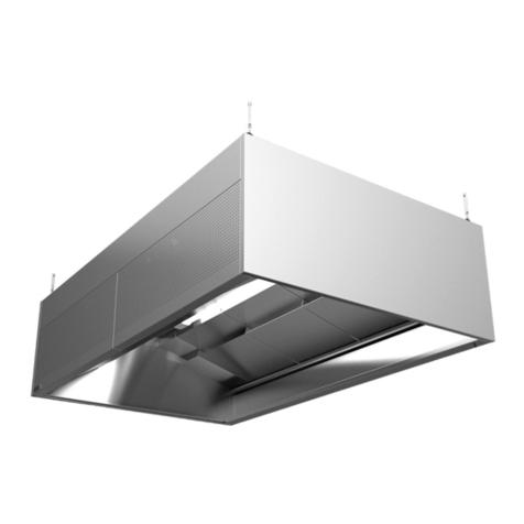
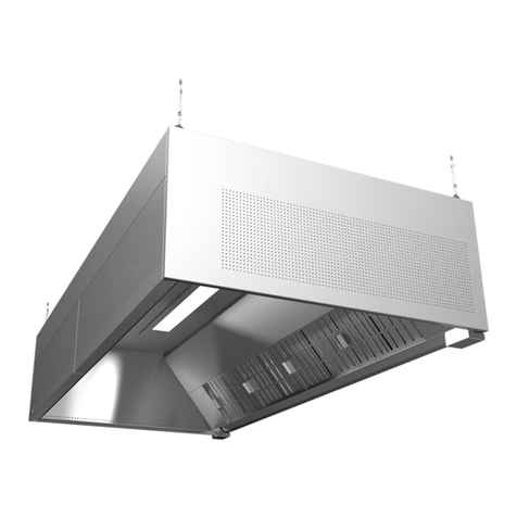
ETS NORD EOZ-1 User manual

NORDcanopy
EOZ – External Ozone Cleaning System
Installation Guide

www.etsnord.com
2RDM-59-0322
®NORDcanopy |EOZ installation guide
Table of contents
Safety notes 3
Installation flowchart 3
1. Check the product shipment 4
2. System overview 5
3. Mount the EOZ 7
4. Install the Control Panel 11
5. Electrical Installation 13
6. Measure and adjust airflow 19
7. Setting Ozone Module addresses 20
Control Panel display messages 26
Facts about ozone 27
Limited warranty of device 27
Service and maintenance 27

Images are for illustrative purposes.
We reserve the right to make changes. RDT-59-0322 3
®NORDcanopy |EOZ installation guide
Safety notes
This manual consists of important information on the instruction and safety of External Ozone Cleaning System.
Read this manual carefully before installing, commissioning, or performing maintenance or repair work on the
system.
• Always wear appropriate protective clothing when handling the equipment.
• External Ozone Cleaning System is intended only for the treatment of exhaust air as described in these
instructions.
• External Ozone Cleaning System uses high voltage to create an electric charge that generates ozone
(O₃). Ozone significantly reduces odor, grease, mold and bacteria. ETS NORD AS disclaims any liability
in the case that the product is not used in accordance with the manufacturer’s instructions contained in
this manual.
Installation flowchart
For ease of installation and service, it is suggested the installing contractor have the following tools and
components on hand:
• Narrow 2mm flat-head screwdriver
• #1 Phillips screwdriver
• T4 screwdriver
• Silicone gun
• Silicone
• Rivet gun
• Stainless steel rivets
• M8 threaded rod
• M8 nuts
Check the
product
shipment
Mount EOZ
Connect
pressure
measure-
ment tubes
Mount Control
Panel
Connect
supply
mains for
control
panel and
EOZ
Perform
electrical
installation
of the
system
Connect
data wiring
for control
panel and
EOZ
Measure the
airflow
Setting
Ozone
Module
addresses
(in case of
multiple EOZ)
Report the
possibility of
commissio-
ning

www.etsnord.com
4RDM-59-0322
®NORDcanopy |EOZ installation guide
1. Check the product shipment
Check that the parcel contains all components listed below and that there is no visible damage. Notify both the
freight forwarder and supplier immediately of any damage or missing components.
Before installing the device read through the entire instruction material.
The EOZ External Ozone Cleaning System consists of two key components:
• EOZ with Ozone module(s)
• Control Panel
The EOZ package contains:
• One or more Ozone Modules (pre-installed)
• Power cable with IEC C13 plug (3m)
• Pressure measurement hose (5m)
• Adhesive cable tie mounts (10 pcs)
• Cable ties (10 pcs)
The Control Panel package contains:
• Control Panel
• One sheet of Ozone Module device address identification labels*
* Only used if more than one EOZ unit is installed on the premises.
In the kit:
A – Adhesive cable tie mount
B – Cable tie
C – Ozone module
D – Power cable
E – Pressure measurement hose
F – Measurement nozzle
A B C D
EF

Images are for illustrative purposes.
We reserve the right to make changes. RDT-59-0322 5
®NORDcanopy |EOZ installation guide
2. System overview
The Ozone Modules within the EOZ chassis produce ozone gas. Ozone (O3) is a very eective oxidant, and when
mixed into a kitchen exhaust airstream it breaks down grease and odor particles to water vapor, carbon dioxide
and dry minerals, all natural products of oxidation which exit the exhaust system.
Note! For best results with odor reduction, the reaction time for ozone within a kitchen exhaust system should
be at least two seconds. However, longer exposure can further improve results. This time should be taken into
account during the design phase of the kitchen exhaust system
Installation method
ATTN! EOZ must be installed in the correct orientation. The direction of the airflow must correspond
ATTENTION!
•
During the installation, keep in mind to leave the service area free of obstructions for ease of future
maintenance.
• EOZ chassis can be mounted in any position. It is very important to keep in mind that the direction of the
airflow must correspond with the arrow on the EOZ chassis as shown below.
•
All duct installation materials between the outlet of the EOZ unit and the main exhaust duct, including
screws, rivets and the connecting flange, must be stainless steel (AISI 316 ).
1 – KRI Regulating damper (for installation refer to the KRI manual)
2 – EOZ Ozonator
* Supply air from AHU
1
AISI 316
2
Supply air*
Treated air
Exhaust air
Ozonated air
Kitchen ventilation canopy
Ozonated air
Treated air
Exhaust air
Supply air*
Service area
min 500 mm

www.etsnord.com
6RDM-59-0322
®NORDcanopy |EOZ installation guide
EOZ Dimensions and Technical Data
Model Modules
quantity
b
(mm)
c
(mm)
Ød
(mm)
Weight
(kg)
Voltage
(V, Hz)
Max power
(W)
EOZ-1 1 250 125 125 13 230/50 300
EOZ-2 2 450 225 160 20 230/50 600
EOZ Supply air end EOZ Exhaust air end
8
9
10
6
4
3
1
5
2
7
1 - Suspension brackets
2 - Supply air connection
3 - Power socket
4 - Data cable socket
5 - Status LED(s)
6 - Ozone Module(s)
7 - Service hatch
8 - Exhaust air connection
9 - Exhaust pressure nozzle
10 - Ambient pressure nozzle(s)
640
Ød
12,5
42,5
135
c
b
270
NOTE! Installation may only be carried out by specialist and authorized persons in accordance with
local , regional, national standards and regulations.

Images are for illustrative purposes.
We reserve the right to make changes. RDT-59-0322 7
®NORDcanopy |EOZ installation guide
3. Mount the EOZ
The EOZ unit may be installed in any convenient location in the kitchen space, ideally with easy access to supply
air and within 3m of the canopy connection to the exhaust duct.
Keep in mind, however, that all duct installation materials between the outlet of the EOZ unit and the main exhaust
duct, including screws, rivets and the connecting flange, must be stainless steel (AISI 316).
Hanging the EOZ chassis
Begin by mounting four (4) M8 threaded rods to the ceiling. Suspend the EOZ unit from the rods with M8 nuts
and washers as shown . Adjust height as needed.
NOTE! Direction of the airflow must correspond with the arrow on the EOZ.
4x M8

www.etsnord.com
8RDM-59-0322
®NORDcanopy |EOZ installation guide
Connect to the ventilation ducts
After the EOZ unit has been securely attached to the ceiling, connect the supply air and exhaust air ducts.
Note: Materials for the supply air side may be chosen at the discretion of the installer. However, all materials
used between the outlet of the EOZ unit and the main exhaust duct, including screws, rivets and the connecting
flange, must be stainless steel (AISI 316).
Secure the ducts with stainless steel rivets or sheet metal screws from both sides and ensure the connection
is airtight.

Images are for illustrative purposes.
We reserve the right to make changes. RDT-59-0322 9
®NORDcanopy |EOZ installation guide
Connect the pressure measurement hose to the exhaust duct
Begin by installing the measurement nozzle onto the exhaust duct or canopy exhaust chamber with a stainless
steel rivet or sheet metal screw. Mount the nozzle to the exhaust duct ahead of the EOZ connection pipe as
shown below.
Next, fasten one end of the long measurement hose provided with the shipment to the newly installed
measurement nozzle. Trim the hose to an appropriate length and run the free end of the hose to the right
measurement nozzle on the EOZ unit as shown below.
NOTE! This hose must be connected between the EOZ unit and main exhaust duct for proper
operation.
Exhaust duct
Stainless steel rivet
NOTE! Be sure that the hose is connected to the proper nozzle on the EOZ and that the caps of the
nozzles has been removed.

www.etsnord.com
10 RDM-59-0322
®NORDcanopy |EOZ installation guide
Finally, secure the hose to the duct using adhesive cable tie mounts and cable ties that can found in the EOZ
packaging. .
<400
NOTE! Be careful not to tighten the cable ties to strongly to ensure that the
airflow through the hose is not blocked.

Images are for illustrative purposes.
We reserve the right to make changes. RDT-59-0322 11
®NORDcanopy |EOZ installation guide
4. Install the Control Panel
Control Panel overview
Disassembly the control panel
Choose a visible and easily accessible location
in the kitchen suitable for mounting the Control
Panel. Avoid positioning it near any sources of
moisture or heat.
The housing must be disassembled into three
parts. Remove the two fixing screws on the
sides of the case.
2
1
3
1 - Anchor points for wall mounts
2 - Data cable bushings
3 - RJ-45 connector
69
121
181

www.etsnord.com
12 RDM-59-0322
®NORDcanopy |EOZ installation guide
Mounting the backplate
Before mounting the backplate apply an even strip of waterproof silicone along the rear of the backplate as
pictured below.
Fasten the backplate to the wall with its cable cutout facing downward, preferably at eye level but not higher
than 180 cm from the floor.

Images are for illustrative purposes.
We reserve the right to make changes. RDT-59-0322 13
®NORDcanopy |EOZ installation guide
5. Electrical Installation
The EOZ 3.1 External Ozone Cleaning System must be interlocked with the exhaust system, so that when the
exhaust ventilation is not running, no electrical power is supplied to the ozone system. See the sample diagram
below as one possible option to accomplish this function.
A maximum of 4 Ozone Modules and one alarm panel may be connected a single 10A C-type (slow) circuit
breaker. Remember to label the circuit breakers used in the distribution board.
NOTE! Electrical installation must be performed by an authorized electrician and follow local, regional
and national standards and regulations.
F1 F2
K1 KL1
<I
L1
N
L1
DISTRIBUTION BOARD NO. 1 DISTRIBUTION BOARD NO. 2
VENTILATION UNIT
F1 - Circuit breaker
F2 - EOZ Module + Control Panel
Current relay
(0...100%)
AC relay
Motor, exhaust ventilation fan systems +
motor drive
EOZ
<I
K
Junction box
<I
I/O
Building automation
PLC
Modbus
BACnet (TCP/IP)
ModBus (TCP/IP)
Ethernet (TCP/IP)
Control Panel

www.etsnord.com
14 RDM-59-0322
®NORDcanopy |EOZ installation guide
Connecting the main electrical supply
Control Panel power cables may be fed through rear wall. Connect the 230V supply cable to the power supply
terminals L, N and PE, as shown in the diagram.
EOZ is supplied with a power cable that can be found inside the packaging. Connect it to the EOZ as shown
below.
230V supply cable
Power supply
PE
L
N

Images are for illustrative purposes.
We reserve the right to make changes. RDT-59-0322 15
®NORDcanopy |EOZ installation guide
Control Panel and EOZ data wiring
There are three cables that must be connected to the Control Panel. Data cable (3x0,25mm2) for communication
between Control Panel and EOZ unit, I/O cable (5x0,5mm²) for connecting to the building automation and LAN
cable to access the Control Panel via internet.
Wiring Control Panel to the EOZ unit is done with 3x0,25 mm² shielded data cable.
Begin by installing the EOZ data cable between the EOZ unit and the Control Panel. Note the colors of the wires
used when connecting the three terminals A, B+ and C.
Next, connect the cable to the EOZ as shown below. Ensure that the cable color used for each terminal is
the same on both devices.
Control Panel EOZ-2
3x0,25 mm2
Data cable
A
B+
C

www.etsnord.com
16 RDM-59-0322
®NORDcanopy |EOZ installation guide
The max number of Ozone Modules connected to a single Control Panel is 99, with a maximum length of 500m.
However, it may be advantageous to have multiple Control Panels in larger facilities for local monitoring purposes.
To connect multiple EOZ and/or Ozone Modules together they must be connected sequentially (“daisy-chained”)
from the Control Panel to the nearest device, then to next and so on. However, please note that although the
physical cabling is “chained” from one device to the next, the data cables are connected in a parallel format. In
this way data communications between devices will remain active even if one of them is powered o,
malfunctioning, or unplugged and removed.
Thus, each A, B+ and C data wire leading in from devices of any EOZ in the chain should share the same terminal
screw in its respective connector.
NOTE! The following section applies only when installing multiple EOZ or Ozone Modules. If
installing only one unit, please skip to section “Control Panel and I/O wiring”.
Control Panel EOZ-2 EOZ-1 nr. 1 EOZ-1 nr. 2
3x0,25 mm23x0,25 mm23x0,25 mm2
C
B+
A-
IN
OUT

Images are for illustrative purposes.
We reserve the right to make changes. RDT-59-0322 17
®NORDcanopy |EOZ installation guide
Control panel and I/O cable wiring
Next, install the I/O data cable for your building automation system or for future upgrades rout the I/O cable to
the junction box.
Connect the five (5) terminals DI1, DI2, DO1, DO2 and COM+ and mark the other ends of the wires within the
junction box with their corresponding terminal assignments.
Rout the other end to a junction box that is situated near or on top of the EOZ unit.
Never drill or screw into the EOZ chassis.
Junction boxControl panel
PLC / Building automation
I/O cable
DI2
DI1
COM+
DO2
DO1
L
PLC
I/O

www.etsnord.com
18 RDM-59-0322
®NORDcanopy |EOZ installation guide
Control panel LAN cable wiring
Finally,
connect the EOZ system to the local area network, connect the LAN cable to the Control Panel by
unplugging the existing short LAN jumper cable inside and connect your LAN cable straight to the port on the
board as seen below.
LAN cable must be connected to a network switch or to the closest LAN socket.
Control Panel assembly
Reassemble the housing in reverse order, with the smaller LED display above the larger one. Ensure the text on
the plexiglass is oriented correctly and fasten the housing with the two fixing screws on the sides.

Images are for illustrative purposes.
We reserve the right to make changes. RDT-59-0322 19
®NORDcanopy |EOZ installation guide
6. Measure and adjust airflow
1. Measure the airflow at the KRI damper installed before the EOZ to find operational airflow of the unit. For
more information refer to
KRI regulating damper installation guide
.
2.
Measure the air pressure dierence of the EOZ unit from both nozzles as seen in the picture (both
measurements need to be approximately the same).
Confirm that the system airflow and pressures fall within the following specifications:
Model
Operational airflow
(l/s)
1
Pressure dierence
(Pa)
2
Pressure drop
(Pa)
EOZ-1 30 -20 35
EOZ-2 50 -25 30
1 2

www.etsnord.com
20 RDM-59-0322
®NORDcanopy |EOZ installation guide
7. Setting Ozone Module addresses
All Ozone Modules connected to the same Control Panel must be set to a unique device address. The Ozone
Module(s) inside of an EOZ chassis have been set at the factory to the following specifications:
EOZ-1: Device address is “3”
EOZ-2: Device addresses are “1” and “2”
For installations with multiple EOZ units, it is important to ensure that there are no overlapping address conflicts:
* All Ozone Modules in each EOZ chassis or canopy must have a unique device address.
* Address identification labels must be added to the service hatch on EOZ units. In case of model EOZ-2, both
address labels must be placed upon the unit.
Opening EOZ hatch
Start by opening the front panel by opening two (2) clamps that are holding the panel.
NOTE! The following section applies only when installing multiple EOZ units. If installing only one unit,
the Ozone Module addresses do not need to be changed and you may skip this section.
NOTE! Turn o and disconnect the electrical power cord from the EOZ chassis before proceeding.
This manual suits for next models
2
Table of contents
Other ETS NORD Fan manuals
Popular Fan manuals by other brands

S&P
S&P CAD HE 325 EC V BASIC manual

Home Decorators Collection
Home Decorators Collection KENSGROVE YG493ODC-MBK Use and care guide

Bestron
Bestron DFT25R instruction manual

Vallox
Vallox 90 SE Series Instructions for use and maintenance

Kiwi
Kiwi KFAN 7631 instruction manual

TREVIDEA
TREVIDEA G3 Ferrari LEVANTE user manual