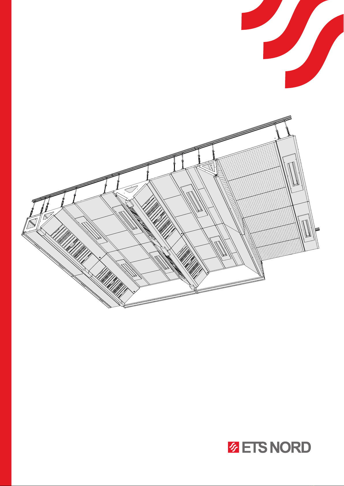
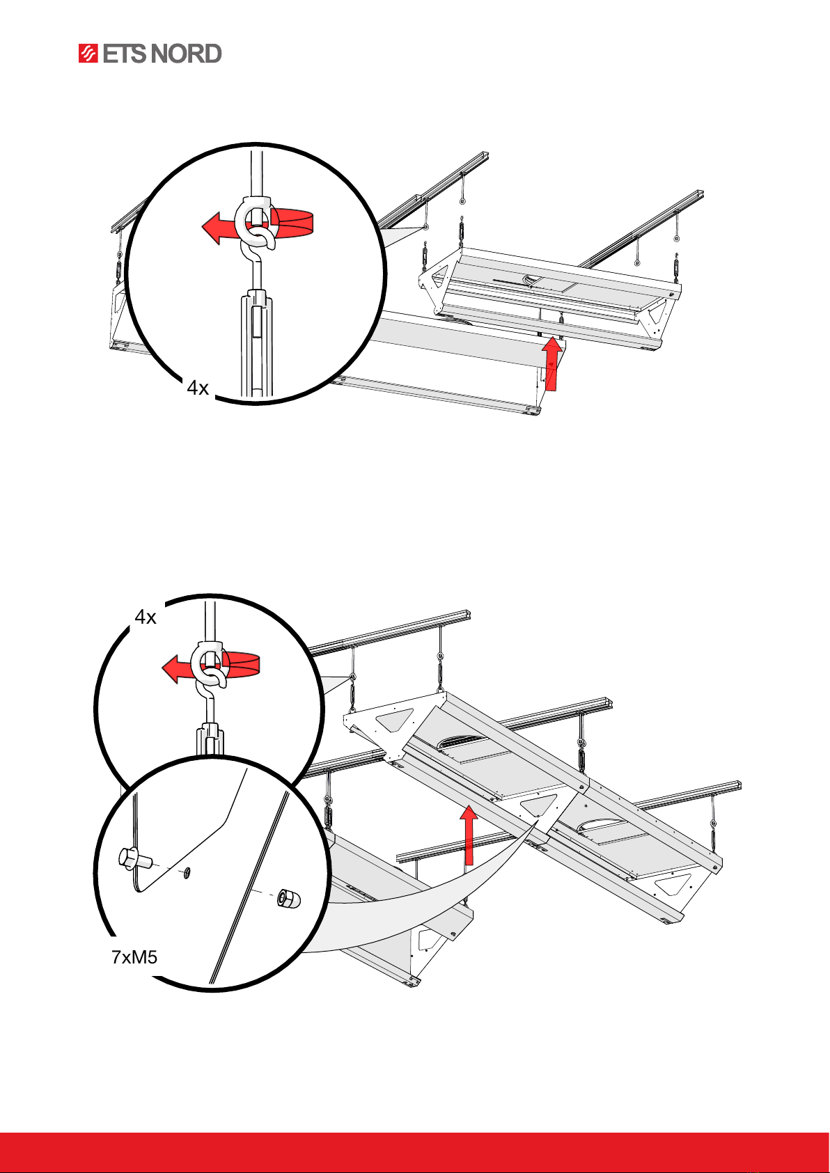
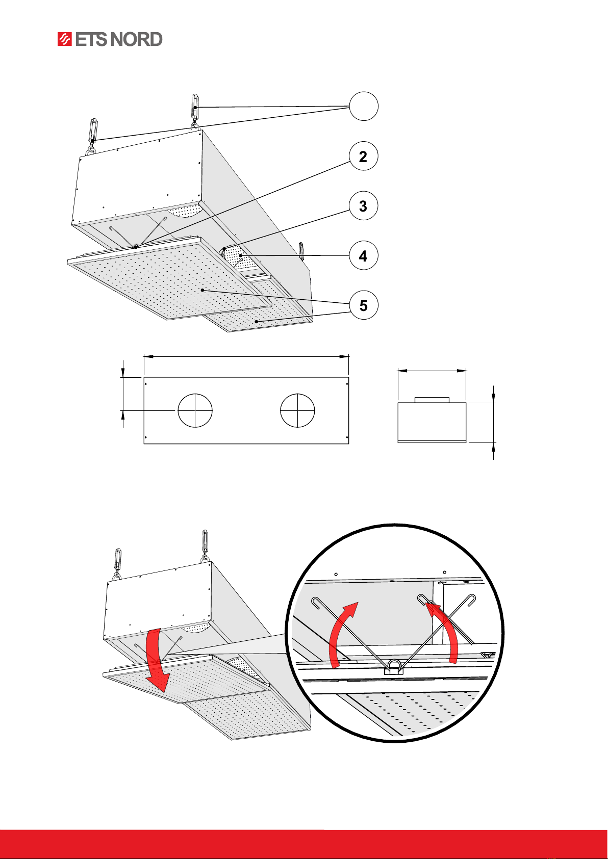
ETS NORD NORDcanopy Service manual

NORDcanopy
HC Ventilation Ceiling installation, use and
maintenance manual
www.nordcooking.com

www.etsnord.com
2RDM-57-0222
NORDcanopy |HC
®
Table of Contents
1. HCE Exhaust Wall Module 4
2. HCI Exhaust V-Module 5
3. HCG AirGrip Module 7
4. HCV Vertical Supply Air Module 9
5. HCH Horizontal Supply Air Module 11
6. HCAH Horizontal Supply Air Module 13
7. Installing L-profiles 15
8. HCL Led Light Module 16
9. HCF Ceiling Panel 18
10. HCM Noise Absorbing Ceiling Panel 18
11. Installing the Ozonator 19
12. Corner Details 21
13. Additional Components 23
14. Measuring and adjusting airflow 24
15. Replacing the luminaires 26
16. Kitchen canopy maintenance 26

Images are for illustrative purposes.
We reserve the right to make changes. 3
RDM-57-0222
®NORDcanopy |HC
In the kit:
4 61 52 3
98 6107
1 – MEFA fastening system
2 – HCE Exhaust Wall Module
3 – HCI Exhaust V-module
4 – HCG AirGrip Module
5 – HCV Vertical Supply Air Module
6 – HCM Noise Absorbing Ceiling Panel
7 – HCAH Horizontal Supply Air Module
8 – HCL LED Light Module
9 – HCF Ceiling Panel
10 – HCH Horizontal Supply Air Module
A – Loop nut
B – Self-tapping screws
C – M5 bolts and capped nuts
D – L-profile
E – HFK grease filter
F – Blind panel for grease filter rail
G – Grease collection container
A B C D
E F G

www.etsnord.com
4RDM-57-0222
®NORDcanopy |HCE
1. HCE Exhaust Wall Module
1.1 Hanging the HCE Exhaust Wall Module
400
440
L
240
D
E
F
C
1
2
3
4
B
A
3
2
1
5
C
D
6
7
8
A
B
ETS NORD AS
LEHT:
1 / 8
MÕÕT:
1:3
Tähis:
Nimetus:
Materjal:
Kinnitas
Kontrollis
Teostas
12.08.2021
Hannes Lung
HCE
HCE E1
MASS:
5
6
4
3
2
7
1
1 – Suspension points
2 – Exhaust air connection
3 – Adjustment plate for exhaust air
4 – HFK Grease Filter
5 – Airflow measuring nozzles
6 – Blind plate for grease filter rail
7 – Grease collection container
x4

Images are for illustrative purposes.
We reserve the right to make changes. 5
RDM-57-0222
®NORDcanopy |HCI
1.2 Sequential connection of the HCE Exhaust Wall Modules
2. HCI Exhaust V-Module
6xM5
5
7
6
4
3
2
1
1 – Suspension points
2 – Exhaust air connection
3 – Adjusting plate for exhaust air
4 – HFK Grease Filter
5 – Airflow measuring nozzles
6 – Blind panel for grease filter rail
7 – Grease collection container
660
335
L
330
D
E
F
C
1
2
3
4
B
A
3
2
1
5
C
D
6
7
8
A
B
ETS NORD AS
LEHT:
2 / 8
MÕÕT:
1:3
Tähis:
Nimetus:
Materjal:
Kinnitas
Kontrollis
Teostas
12.08.2021
Hannes Lung
HCI
HCE E1
MASS:

www.etsnord.com
6RDM-57-0222
®NORDcanopy |HCI
2.1 Hanging the HCI Exhaust V-Module
2.2 Sequential connection of HCI Exhaust V-Modules
4x
7xM5
4x

Images are for illustrative purposes.
We reserve the right to make changes. 7
RDM-57-0222
®NORDcanopy |HCG
3. HCG AirGrip Module
3.1 Hanging the HCG AirGrip Module
1 – Suspension points
2 – Housing hatch
3 – Supply air connection
4 – Horisontal AirGrip system
5 – Vertical AirGrip system
3
5
2
4
1
400
L
150
2x

www.etsnord.com
8RDM-57-0222
®NORDcanopy |HCG
3.2 Sequential connection of HCG AirGrip Modules
3.3 Connecting the HCG AirGrip Module to the ventilation ceiling modules
4xM5
2x
Number of screws:
HCE - 6 pcs
HCI - 7 pcs
HCG - the holes must be
drilled, the recommended
amount is 4 pcs
HCE
HCI
HCG

Images are for illustrative purposes.
We reserve the right to make changes. 9
RDM-57-0222
®NORDcanopy |HCV
4. HCV Vertical Supply Air Module
4.1 Opening the HCV Vertical Supply Air Module front panel
4
3
5
2
1
1 – Suspension points
2 – Front panel lock
3 – Supply air connection
4 – Supply air adjusting plate
5 – Front panels
500
300
L
250

www.etsnord.com
10 RDM-57-0222
®NORDcanopy |HCV
4.2 Hanging the HCV Vertical Supply Air Module
4.3 Sequential connection of HCV Vertical Supply Air Modules
4x
4xM5
4x

Images are for illustrative purposes.
We reserve the right to make changes. 11
RDM-57-0222
®NORDcanopy |HCH
5. HCH Horizontal Supply Air Module
5.1 Opening the HCH Horizontal Supply Air Module front panel
3
2
7
4
6
1
5
1 – Suspension points
2 – Supply air connection
3 – Supply air adjustment plate
4 – Front panel
5 – AirGrip air nozzle system
6 – Auxiliary supply opening
7 – Front panel lock
400
345
L
180
D
E
F
C
1
2
3
4
B
A
3
2
1
5
C
D
6
7
8
A
B
ETS NORD AS
LEHT:
6 / 8
MÕÕT:
1:3
Tähis:
Nimetus:
Materjal:
Kinnitas
Kontrollis
Teostas
12.08.2021
Hannes Lung
HCH
HCE E1
MASS:

www.etsnord.com
12 RDM-57-0222
®NORDcanopy |HCH
5.2 Hanging the HCH Horizontal Supply Air Module
5.3 Sequential connection of HCH Horizontal Supply Air Modules
6xM5
6xM5
4x

Images are for illustrative purposes.
We reserve the right to make changes. 13
RDM-57-0222
®NORDcanopy |HCAH
6. HCAH Horizontal Supply Air Module
6.1 Opening the HCAH Horizontal Supply Module front panel
1 – Suspension points
2 – Supply air connection
3 – Supply air adjustment plate
4 – Front panel
5 – Auxiliary supply openings
6 – Front panel lock
7 – Vertical AirGrip system
8 – Horizontal AirGrip system
L
180
400
345
A A
B B
C C
D D
E E
F F
4
4
3
3
2
2
1
1
DRAWN
CHK'D
APPV'D
MFG
Q.A
UNLESS OTHERWISE SPECIFIED:
DIMENSIONS ARE IN MILLIMETERS
SURFACE FINISH:
TOLERANCES:
LINEAR:
ANGULAR:
FINISH:
DEBURR AND
BREAK SHARP
EDGES
NAME
SIGNATURE
DATE
MATERIAL:
DO NOT SCALE DRAWING
REVISION
TITLE:
DWG NO.
SCALE:1:20
SHEET 1 OF 1
A4
WEIGHT:
HCAH
8
7
3
2
6
4
5
1

www.etsnord.com
14 RDM-57-0222
®NORDcanopy |HCAH
6.2 Hanging the HCAH Horizontal Supply Module
6.3 Sequential connection of HCAH Horizontal Supply Modules
4x
3xM5
4x

Images are for illustrative purposes.
We reserve the right to make changes. 15
RDM-57-0222
®NORDcanopy |HC
7. Installing L-profiles
7.1 Installing L-profiles on end surfaces
7.2 Installing L-profiles on the sides of the ventilated ceiling chambers

www.etsnord.com
16 RDM-57-0222
®NORDcanopy |HCL
7.3 Connecting the L-profile to the HCV Supply Air Modul
8. HCL LED Light Module
8.1 Connecting L-profiles to the HCL LED Light Module
3
2
1
1 – Suspension points
2 – LED luminaire
3 – Openable lighting case
250-500
60
L

Images are for illustrative purposes.
We reserve the right to make changes. 17
RDM-57-0222
®NORDcanopy |HCL
8.2 Exhaust side HCL LED Light Module installation
8.3 Installing L-profiles on the HCL LED Light Module
8.4 Installing HCL LED Light Modules
2x
4x

www.etsnord.com
18 RDM-57-0222
®NORDcanopy |HCF/HCM
9. HCF Ceiling Panel
9.1 Installing the HCF Ceiling Panel
10. HCM Noise Absorbing Ceiling Panel
10.1 Installing the HCM Noise Absorbing Ceiling Panel
500
L
500

Images are for illustrative purposes.
We reserve the right to make changes. 19
RDM-57-0222
®NORDcanopy |HC
11. Installing the Ozone Generator
11.1 Attaching the OZ fitting
11.2 Installing the Ozone Generator on the Exhaust Module
6x

www.etsnord.com
20 RDM-57-0222
®NORDcanopy |HCA
11.3 Installing the Ozone Generator electrical system (230V, 50Hz)
The ozone generator system must be interlocked with the exhaust system, so that when the exhaust
ventilation is not running, no electrical power is supplied to the ozone system. See the sample diagram
below as one possible option to accomplish this function.
A maximum of 4 Ozone Modules and one alarm panel may be connected a single 10A C-type (slow) circuit
breaker. Remember to label the circuit breakers used in the distribution board
For further installation and technical information, please consult the product manuals provided with
your shipment, or contact your ETS NORD representative to obtain all available documentation
F1 F2
K1 KL1
<I
L1
N
L1
DISTRIBUTION BOARD NO. 1 DISTRIBUTION BOARD NO. 2
VENTILATION UNIT
CANOPY
F1- Circuit breaker
F2- Ozone Module + Control Panel
Current relay
0...100%
AC relay
Motor, exhaust ventilation fan systems +
motor drive
OZ3 no.1OZ3 no.2
<I
OZ3 no.3
Junction box
Control Panel
<I
I/O
Building automation
PLC
Modbus
BACnet (TCP/IP)
ModBus (TCP/IP)
Ethernet (TCP/IP)
NOTE! Electrical installation must be performed by an authorized electrician and follow local, regional
and national standards and regulations.
Other manuals for NORDcanopy
5
Table of contents
Other ETS NORD Fan manuals
Popular Fan manuals by other brands

Craftmade
Craftmade Cecilia Unipack CCU52 installation guide

Salda
Salda SMARTY RV MOUNTING AND INSTALLATION INSTRUCTION

aldes
aldes H/E240 Operation & maintenance manual

Vents
Vents VP Series user manual

Vents-us
Vents-us TT PRO 100 installation guide

Trane
Trane TVR LX 4TVL0006DF000AA Technical & service manual

Bestron
Bestron SUMMER BREEZE AFT770WRC instruction manual

Stadler Form
Stadler Form Peter Little operating instructions

Vortice
Vortice PUNTO FOUR MFO 90 Instruction booklet

Holmes
Holmes HFH111T owner's guide

Carrier
Carrier FX4D series installation instructions

homevent
homevent MORI HR NEXT Installation & maintenance manual