ETT DESHU Owner's manual

Énergie Transfert Thermique
Technical instructions
for Operation & Maintenance
A different climate
Environmental control solutions
July 2016
Double ow dehumidier
DESHU

2
Energie
Transfert
Thermique
Contents
A. Equipment performance................................................................................................................................ 3
B. Maintenance intervals....................................................................................................................................... 3
C. Regulatory requirements................................................................................................................................. 5
D. Specic maintenance recommendations................................................................................ 7
E. Starting/Stopping the unit.............................................................................................................................. 9
F. Controller operation.......................................................................................................................................... 10
G. Diagnostics and troubleshooting support ............................................................................... 13
Information contained in this document has been prepared by qualied ETT specialists.
We are doing our best to ensure its completeness and accuracy but it does not constitute a guarantee.
This information is given in good faith, any use of the equipment not in accordance with the instructions
and warnings is done at the user's own risk.
3
MARK-NOT_01.00-EN
ETT may change equipment’s data & design without prior notice.
Specications given in this document are for information only and are not contractual.
Technical instructions
for Operation & Maintenance
ETT may change equipment’s data & design without prior notice.
Specications given in this document are for information only and are not contractual.
A. Equipment performance
• The validity of the guarantee is conditional upon strict compliance with instructions presented in this
document.
• Proper operation and maintenance:
>maintains units performance;
>extends equipment service life;
>reduces the risk of unit failure;
>allows energy costs management;
>ensures regulatory compliance (compulsory checks based on local regulations).
ETT Services is here to help you get the most out of your installation.
+33 (0)2 98 48 02 22
Contact your local ETT Services adviser.
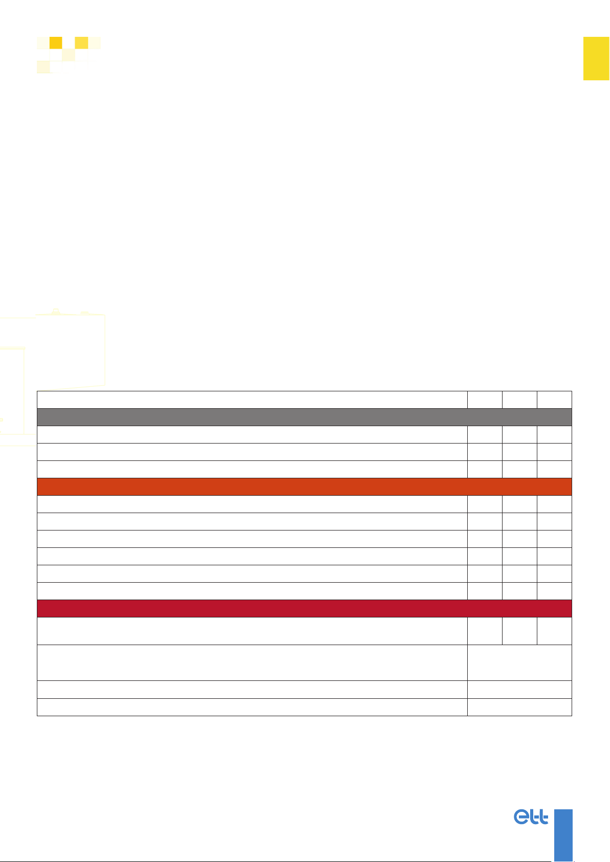
B. Maintenance intervals
Maintenance intervals: Q (Quarterly), S (Semi-annually), A (Annually)
Operations Q S A
General control
Check casing X
Clean siphons and condensate drain X
Operating time report X
Electricity / Control
Check controller X
Set clock and operating schedule X
Check setpoints X
Tighten electrical connections X
Check temperature probes X
Replace humidity probes sensor element (if applicable) X
Consumables
Clean or replace lters (1) 48 mm
X
98 mm
X
Replace smoke detector head
Nota: Maintenance intervals are given as indication only. Replacement may be needed more frequently in polluted
atmospheres.
Every 2 years
Replacement of the smoke detection box battery Every 2 years
Replace humidity probe and/or sensor element (if applicable) Every 2 years
4
MARK-NOT_13.00-EN ETT may change equipment’s data & design without prior notice.
Specications given in this document are for information only and are not contractual.
Technical instructions
for Operation & Maintenance
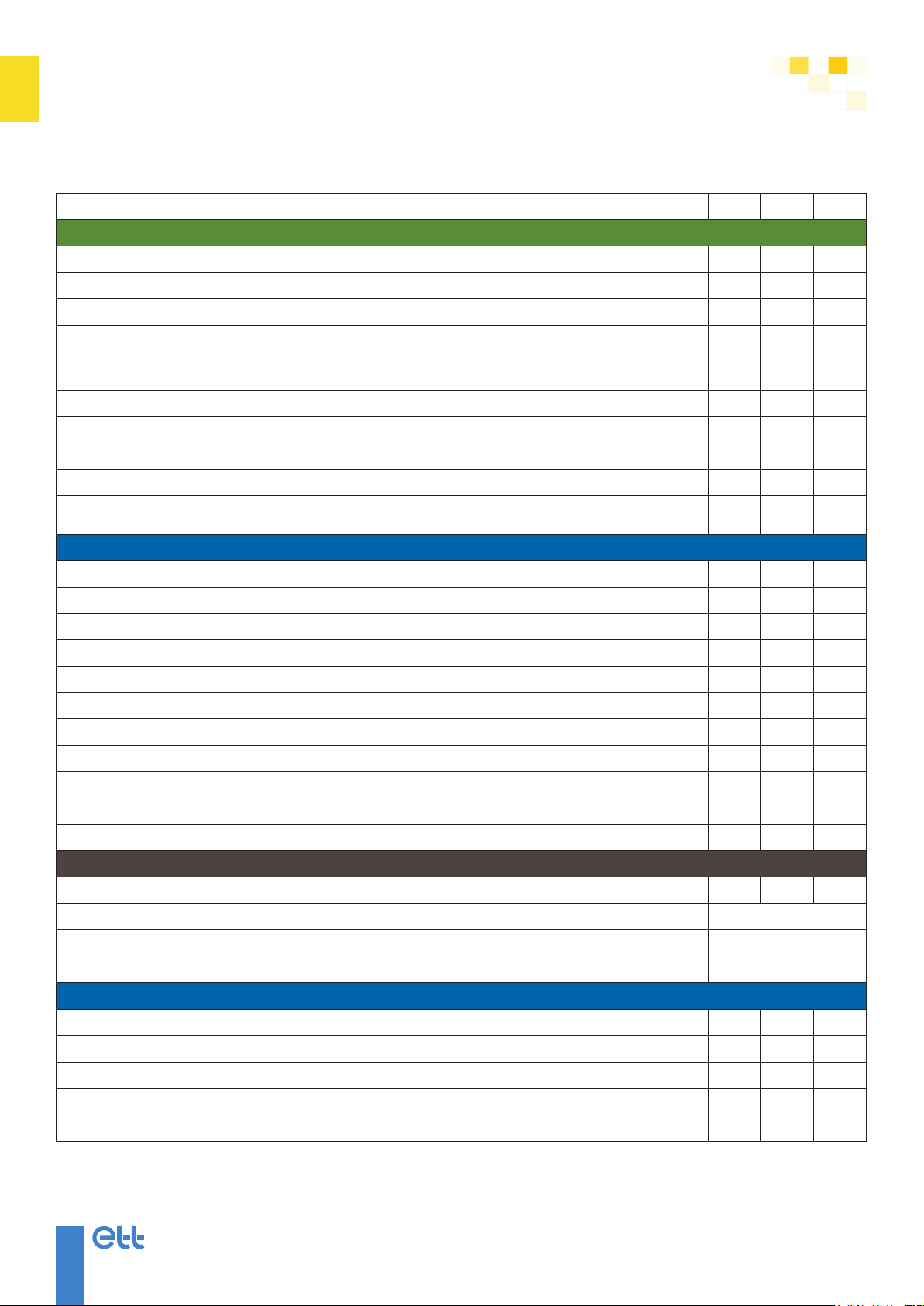
Maintenance intervals: Q (Quarterly), S (Semi-annually), A (Annually)
Operations Q S A
Ventilation
Servomotors and dampers control X
Control and cleaning of fans turbines X
Grease fans bearings or replace fan bearings grease cartridges X
Fans rotation speed and air ow rates control
Nota: In case of insufcient ow rate, apply recommendations described in “Specic maintenance recommendations”, p. 7
X
Check air ducting (cleanliness, cones, valves, etc.) X
Ventilation motors control X
Control of belts and their tension (if unit with belts) X
Change of belts (if unit with belts) X
Fans motors intensities report X
Check ventilation safety devices (ow rate, lters fouling, re contact, smoke detector,
post-ventilation, etc.) (1) X
Refrigeration circuits
Check oil level, adjust if necessary X
Compressor(s) intensities control X
Check pressures: HP and LP X
Control superheat and subcooling X
Check and clean refrigerant-to-air exchangers (1) X
Check expansion valve, adjust if necessary X
Electronic expansion valves: check parameters X
4-way valve(s) control X
Check refrigeration safety devices (HP & LP pressure switches, thermostats, etc.) X
Auxiliary condenser: check and adjust water ow rate X
Tighten refrigeration pipe clamps: adjust or replace if necessary X
Regulatory controls
Leakage checking (based on unit t CO2e) (2) >500 >50 >5
Pressure equipment inspection (2) Every 40 months
Pressure equipment certication (2) Every 10 years
Inspection of air-conditioning systems and heat pumps (2) Every 5 years
Heating (if applicable)
Check hot water coil (cleanliness, tightness) X
Check water quality in hot water coil X
Check 3-way valve operation X (3)
Check electric heaters X(3)
Check hot water coils (1)

5
MARK-NOT_01.00-EN
ETT may change equipment’s data & design without prior notice.
Specications given in this document are for information only and are not contractual.
Technical instructions
for Operation & Maintenance
Maintenance intervals: Q (Quarterly), S (Semi-annually), A (Annually)
Operations Q S A
Heat pipe (if applicable) (1)
Check heat pipe efciency by measuring temperatures X
Check heat pipe jack operation (if applicable) X
Clean heat pipe X
Rotary exchanger (if applicable) (1)
Check heat exchanger efciency by measuring temperatures X
Control brushes / gaskets tightness X
Check heat exchanger drive motor (1) X
Check heat exchanger belt and belt tension X
Check bearing greasing (if not life-time lubricated) X
Thalassotherapy centres: corrosive/saline atmospheres (1)
Check and clean aluminium drift eliminator (which retains potential large salt or sand particles
from outside) X
Clean or replace G4 lters or washable lters PRP3 X
Clean or replace ne F7 lters or F9 polypropylene lters (also called coalescer lter), do not hold
the breglass media The lter can be cleaned at least twice (desalinate in a tray and dry) X
Cleaning procedure described in “Filtration”, p. 7
Check and clean refrigerant-to-air exchangers (SAKAPHEN coating) - clean with high pressure water
X
Grease fan bearings and shaft (whatever the type). X
Check and clean fans monthly. X
Clean heat exchangers with clear water monthly. X
(1) See “Specic maintenance recommendations”, p. 7.
(2) See “Regulatory requirements”, p. 5.
(3) In Heating mode.
C. Regulatory requirements
1/ Refrigerating system log book (EN 378-2)
Each system having a refrigerant charge, with a CO2 equivalent of 5 tonnes or above, requires its own separate
log book to be maintained.
The logbook shall be prepared by the installer during installation. It shall be updated after every maintenance
operation, as indicated in EN 378-4 standard.
Log books shall include the following information:
>detailed report of each maintenance or repair operation;
>quantity and nature (new, reused, recycled) of refrigerant added during the operation;
>quantity of refrigerant transferred during the operation (see also EN 378-4 standard);
>results of reused refrigerant analysis (if such analysis was performed);
>origin of reused refrigerant;
>system components replaced or modied;
>routine or periodic tests results;
>signicant non-use periods.

6
MARK-NOT_13.00-EN ETT may change equipment’s data & design without prior notice.
Specications given in this document are for information only and are not contractual.
Technical instructions
for Operation & Maintenance
2/ Check tightness
In application of EU regulations, the French decree of 29 February 2016 on certain refrigerants containing
uorinated greenhouse gases states that equipment containing such refrigerants must be periodically
checked for leakage (see table hereafter) by certied personnel and a tightness control certicate must be
issued.
Leak check intervals
Checking frequency Once a year Twice a year 4 times a year
Metric tonnes of CO2equivalent 5 to 50 50 to 500 >500
Fluid
R134a Refrigerant charge (kg) 3.5 to 35 kg 35 to 349.7 kg >349.7 kg
R407c Refrigerant charge (kg) 2.82 to 28.2 kg 28.2 to 281.8 kg > 281.8 kg
R410a Refrigerant charge (kg) 2.39 to 23.9 kg 23.9 to 239.5 kg > 239.5 kg
A label must be attached to the equipment:
• Blue label if the equipment complies with the requirements:
>The operator who performed the inspection must specify his qualification certificate number in the text
area provided at the centre of the label.
>The label indicates the expiry date of the control certificate.
• Red label if a leak is detected and the operator cannot stop it.
>The equipment shall not be charged with refrigerant until proper repairs have been carried out.
3/ Refrigerant handling
Refrigerant handling must comply with French Decree no. 2007-737 and European legislation:
>Technicians must be trained and must hold the relevant F-gasqualication.
>The company employing the operator must hold an F-gasCompanyCerticate authorising its personnel
to handle refrigerant.
>Refrigerant leaks must be handled and declared according to the installation refrigerant charge.

7
MARK-NOT_01.00-EN
ETT may change equipment’s data & design without prior notice.
Specications given in this document are for information only and are not contractual.
Technical instructions
for Operation & Maintenance
4/ Pressure Equipment Directive
Although refrigeration installations fall within the pressure equipment category, they are a special case in
terms of in-service monitoring. In 2014, the French safety ofce of industrial equipment (BSEI) validated a
Technical Guidebook (CTP USNEF - Available on-line in French), which authorises waivers from the French
decree of 15 March 2000 (amended).
>Refrigeration installations shall be inspected at least every 40 months. Periodic inspection shall be
performed by an authorised person, under the responsibility of the operator.
>Refrigeration installations shall be requaliedevery10years. Periodic requalication shall be performed
by an authorised body which shall issue a requalicationcerticate. To avoid damage to the installation,
the hydraulic test is not required.
5/ Inspection of reversible heat pumps and air-conditioning systems
Decree 2010-349 of 31 March 2010
The inspection shall include documentary controls and an assessment of system efciency and sizing
compared with the cooling requirements of the building.
The inspection shall be performed:
>by an authorised person;
>at the owner’s initiative;
>at least every 5 years.
In case of replacement, the new equipment shall be inspected in the calendar year following replacement.
D. Specicmaintenancerecommendations
1/ Heat exchangers cleaning
Clean them using a bristle scrub brush, a vacuum or a compressed air jet if necessary. Rinse with cold and low
pressure water, avoiding spatters on the fan motor. Clean in counter ow of the air ow way.
2/ Filtration
Poor ltration or signicant fouling can affect unit efciency and damage the refrigeration circuit.
Nota:
Filters cannot be cleaned more than 2 or 3 times. Otherwise, ltration performance is
dramatically reduced. If a lter cannot be regenerated, replace it.
3/ Airowratescontrol
Insufcientairowratescanhaveseveralconsequences:
>The compressor operates out of the permitted operating range.
ÜRisk of compressor breakage
>Heat from auxiliary heaters is not evacuated.
ÜRisk of re alarm
>The setpoints are not reached.
ÜLower heating capacity
Incaseofinsufcientairowrates:
>Check supply air dampers operation;
>Check lters for fouling;
>Check exchangers for fouling;
>Check air ducts (re dampers, fouling in ducts, cone connectors).

8
MARK-NOT_13.00-EN ETT may change equipment’s data & design without prior notice.
Specications given in this document are for information only and are not contractual.
Technical instructions
for Operation & Maintenance
4/ Heatpipeorrotaryheatexchangerefciencycontrol
4.1/ Necessary conditions
>Stop compressors and auxiliaries. Only ventilation shall be activated.
>Outside temperature must differ from return air temperature in order to identify energy recovery through
the heat pipe or rotary heat exchanger.
4.2/ Control procedure
>Check fresh air and supply air temperatures on the controller.
>If fresh air and supply air temperatures are the same, the heat pipe or rotary heat exchanger failed to
transfer energy. Heat transfer efciency has diminished.
4.3/ Corrective measure
>Clean the heat pipe or rotary heat exchanger.
>On heat pipes, cleaning does not improve efciency. Check tightness.
4.4/ Heat pipe/Rotary heat exchanger operating principle
Example: Heating mode
5/ Cleaningprocedure:HPEpolypropylenelters(F7-F9)
!Caution:
When cleaning lters, always wear appropriate protective equipment: glasses, gloves and mask.
5.1/ Cleaning with water
>Lay the lter horizontally on the oor.
>Clean with non-pressurised water using a at jet nozzle. Hold the nozzle 20 cm (6”) from the lter to avoid
damage.
>Spray water in the direction of the pleats and rinse thoroughly the brous material.
>Clean the whole surface of the lter during approximately 1 minute.
>Turn the lter over and repeat the procedure on the other side.
>Detergent may be used for better cleaning.
>Drying time will vary based on ambient temperature and humidity conditions.
Nota:
Be sure the lter is completely dry before replacing it into the unit. A lter can be cleaned
twice without affecting ltration efciency.
5.2/ Cleaning with air
>Lay the lter horizontally on the oor.
>Use a compressed air gun.
>Hold the nozzle 15 cm (6”) from the lter to avoid damage.
>Spray air on the whole surface, in the direction of the pleats during approximately 45 seconds.
>Turn the lter over and repeat the procedure on the other side.
+
_
Air rejeté
Air soufflé
Air entrant
Air repris
Fresh air Supply air
Return airExhaust air

9
MARK-NOT_01.00-EN
ETT may change equipment’s data & design without prior notice.
Specications given in this document are for information only and are not contractual.
Technical instructions
for Operation & Maintenance
6/ Actuating detector control
Operation must be controlled periodically, according to regulations applicable to the building. For type 1
detectors (S6), the secondary source must be controlled monthly by holding the "secondary source test"
button for at least 5 seconds. The "power" indicator must remain switched on.
Perform a functional test using an aerosol smoke detector tester. Follow manufacturer's instructions.
E. Starting/Stopping the unit
1/ Unit temporary shutdown
>Stop the unit.
>Do not shut off power to the evaporator crankcase heater (air-to-water, water-to-water heat pump) or
to the line heaters if the unit is installed in an area where the temperature is likely to fall below 0°C. This
operation is not handled automatically.
2/ Start-up after temporary shutdown
No special precautions are required. To start the unit, reverse the procedure outlined in “Unit temporary
shutdown”, p. 9.
3/ Unit seasonal shutdown
>If the heat pump includes water circuits, drain them. Also drain the connection lines if the unit is installed
in an area where the temperature is likely to fall below 0°C.
>Open the main power switch. Remove the fuse block or lock the main switch in opened position.
>If the heat pump is installed in an area subject to condensation, it is recommended to spray oil on
mechanical parts which are likely to rust (fan bearings, pulleys, etc.).
4/ Seasonal start-up
>Perform annual maintenance operations according to “Maintenance intervals”, p. 3.
>Fill the water circuits and bleed the air out as necessary.
>Fully open the compressor discharge valve.
>Open the liquid line stop valve (if applicable).
>Control refrigeration circuit tightness.
>Switch on the main power switch.
>Acknowledge faults on the detection station (if applicable).
>Allow the compressor crankcase heaters to preheat (12 hours).
>Start the system.
>Check operation of all interconnected devices.
>Check oil level and operating pressures after 15 to 20 minutes of operation.
>Make sure that refrigerant ows in a steady stream with no bubbles.
5/ Generating set - EJP (peak load reduction)
Equipment powered by a generating set must be correctly stopped. Refer to the procedure detailed in “Unit
temporary shutdown”, p. 9.
This can be managed manually or by programming the BMS according to feedback from your energy supplier
if you have a peak load reduction agreement.
Failure to take this precaution could result major damage to the unit or cause components to break (electrical
components, compressors). In such circumstances, components are not covered by ETT guarantee.

10
MARK-NOT_13.00-EN ETT may change equipment’s data & design without prior notice.
Specications given in this document are for information only and are not contractual.
Technical instructions
for Operation & Maintenance
F. Controller operation
1/ Main screen
Key Name Description
ALARM
- Press to access current alarms and faults.
- Press and hold to acknowledge alarms.
Nota: Correct the fault on the corresponding component (reset smoke
detector, re thermostat or frost protection, thermal protection, etc.).
PRG
- Press once to access setpoints.
- Press twice to access operating schedule settings.
- Press three times to access clock settings.
ESC - Go back to previous screen.
UP - Press to increase the selected value.
- From main screen: change display.
DOWN - Press to decrease the selected value.
- From main screen: change display.
ENTER - Press to conrm setting.
- Press and hold to start/stop the unit.
UP + DOWN - Press and hold together to access the Controller menu (password
protected).

11
MARK-NOT_01.00-EN
ETT may change equipment’s data & design without prior notice.
Specications given in this document are for information only and are not contractual.
Technical instructions
for Operation & Maintenance
2/ Access to level 0 - User settings
Access to: - Setpoints
- Operating schedule
- Clock setting
+ Hold the UP and DOWN arrow keys simultaneously for 2 seconds.
Password = 0
Use the UP and DOWN arrow keys to scroll through menus.
Press the ENTER key to enter the selected menu.
Use the UP and DOWN arrow keys to scroll through screens.
Press the ENTER key to access screen setpoints.
Use the UP and DOWN arrow keys to select the setpoint to edit.
Press the ENTER key to access the setpoint.
Use the UP and DOWN arrow keys to adjust the setpoint.
Press the ESC key to return to the main screen.

12
MARK-NOT_13.00-EN ETT may change equipment’s data & design without prior notice.
Specications given in this document are for information only and are not contractual.
Technical instructions
for Operation & Maintenance
3/ Access to level 1 - Maintenance
Access to: - Maintenance
- Communication
- Alarms history
- Energy meter
- Inputs / Outputs
- Meter reset
+ Hold the UP and DOWN arrow keys simultaneously for 2 seconds.
Password = 1
Use the UP and DOWN arrow keys to scroll through menus.
Press the ENTER key to enter the selected menu.
Use the UP and DOWN arrow keys to scroll through screens.
Press the ENTER key to access screen setpoints.
Use the UP and DOWN arrow keys to select the setpoint to edit.
Press the ENTER key to access the setpoint.
Use the UP and DOWN arrow keys to adjust the setpoint.
Press the ESC key to return to the main screen.

13
MARK-NOT_01.00-EN
ETT may change equipment’s data & design without prior notice.
Specications given in this document are for information only and are not contractual.
Technical instructions
for Operation & Maintenance
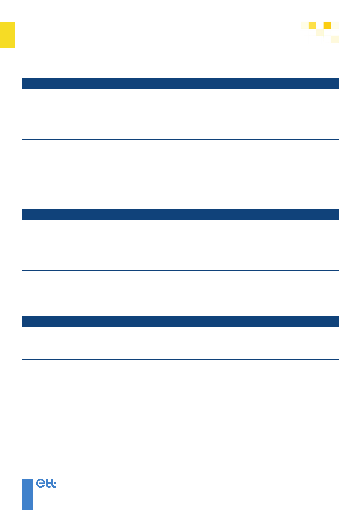
G. Diagnostics and troubleshooting support
1/ Smoke fault
Possible reasons Corrective actions
Smoke detection
- Check for smoke or dust
- Clean detector head
- Replace detector head
- Acknowledge the fault (See “Main screen”, p. 10)
Fouled detector head
- Check for smoke or dust
- Clean detector head
- Replace detector head
- Acknowledge the fault (See “Main screen”, p. 10)
Backup battery out of service - Replace battery
2/ Filter fault
Possible reasons Corrective actions
Fouled lters - Clean lters
- Replace lters
Fouled exchangers - Clean exchangers according to the recommendations
3/ Airowfault
Possible reasons Corrective actions
Fouled lters - Clean lters
- Replace lters
Leakage on air network - Repair air distribution network
Fouled air network - Clean air distribution network
4/ Fire fault
Possible reasons Corrective actions
Lack of air ow rate - Check lters
- Check fan and fan motor
Faulty thermostat - Check thermostat
5/ Antifreeze fault
Possible reasons Corrective actions
Lack of air ow rate - Check lters
- Check fan and fan motor
Faulty thermostat - Check thermostat
Faulty thermostat - Faulty thermostat
14
MARK-NOT_13.00-EN ETT may change equipment’s data & design without prior notice.
Specications given in this document are for information only and are not contractual.
Technical instructions
for Operation & Maintenance
6/ Low pressure fault
Possible reasons Corrective actions
Poor air ow - See “Air ow fault”, p. 13
Fouled lters - Clean lters
- Replace lters
Low pressure switch malfunction - Check pressure switch operation
- Check pressure switch connections
Expansion valve malfunction - Check expansion valve (status, settings, operation).
Refrigerant charge problem - Check tightness
Fouled evaporator - Clean exchangers according to the recommendations
Inefcient defrosting
- Check refrigeration circuit probes
- Check 3-way valve in external box
- Check defrost settings
7/ High pressure fault
Possible reasons Corrective actions
Wrong water ow rate - See “Air ow fault”, p. 13
High pressure switch malfunction - Check pressure switch operation
- Check pressure switch connections
Fouled lters - Clean lters
- Replace lters
Outside T° out of application range - No action
Poor air distribution - Check air distribution network
8/ Refrigeration circuit fault
8.1/ The compressor does not start.
Possible reasons Corrective actions
Electrical protection faults - Check protections
Control security
- Check control parameters
- Check securities
- Reset controller if authorised
Abnormal supply voltage
- Check phases
- Check voltage drop at unit start-up
- Check power supply chain (wire, connections, contactors, etc.)
Ventilation fault - Check external box and internal fan

15
MARK-NOT_01.00-EN
ETT may change equipment’s data & design without prior notice.
Specications given in this document are for information only and are not contractual.
Technical instructions
for Operation & Maintenance
8.2/ The compressor stops.
Possible reasons Corrective actions
Low pressure fault - See “Low pressure fault”, p. 14
High pressure fault - See “High pressure fault”, p. 14
Ipsotherm fault
- Check compressor cooling
- Check ipsotherm probe
- Check lters for fouling
Thermal fault - Check compressor's absorbed current
- Check voltage drop at start-up
Power supply chain interruption
- Check power supply chain (wire, connections, contactors, etc.).
Ventilation fault - Check external box and internal fan
8.3/ The compressor is noisy.
Possible reasons Corrective actions
Knocks - Check compressor suction pressure
Slugging
- Check charge (subcooling)
- Check superheat
- Check expansion valve bulb xation
Grunts
- Check supply voltage
- Check phases
- Galling → broken part
8.4/ The compressor does not stop.
Possible reasons Corrective actions
Stuck contactor - Check contactor
8.5/ Lack of capacity.
Possible reasons Corrective actions
Whistling expansion valve - Check expansion valve settings
- Check charge
Severe overheating - Check expansion valve settings
- Check charge
Pre-expansion - Check drier lter
Wrong ow rates - Check ow rates in air streams

www.ett.fr
Reference: MARK-NOT_13.00-EN
56 Route de Brest - BP26 - 29830 PLOUDALMEZEAU - France
Tel: +33 (0)2 98 48 14 22 - Fax : +33 (0)2 98 48 09 12
Export Contact: +33 (0)2 98 48 00 70 - ETT Services: +33 (0)2 98 48 02 22
Design: ETT - Document printed by an environmentally friendly printer using vegetable based ink on PEFC paper created from sustainably-managed forest.
A different climate
Environmental control solutions
Énergie Transfert Thermique
Table of contents


