ETVAX 7529 Assembly instructions

*
Art. 7529, 7529/D*
Videocitofono serie Tab per sistemi Due Fili Plus
Tab series monitor for Plus Two-Wire Systems
Moniteur de la série Tab pour systèmes Deux Fils Plus
Monitor der serie Tab für systeme Due Fili Plus
Monitor serie Tab para sistemas Due Fili Plus
Monitor série Tab para sistemas Due Fili Plus
Manuale installatore - Installer guide
Manuel installateur - Technisches Handbuch
Instrucciones instalador - Manual do instalador

AAutoaccensione: per l’autoinserimento/autoaccensione del
videocitofono (di default verso la targa Master).
BEsclusione della suoneria: Durante la chiamata, disattiva
la suoneria.
CSerratura: comando per l’apertura serratura (programmazi-
one modificabile con programmatore).
DAusiliario 1 (Luce scale): Per servizio ausiliario (di default
attiva l’attuatore 1 del relè 69RH o 69PH).
E1 Pulsante 1: Pulsante programmabile per attivazione
servizio ausiliario o chiamata intercomunicante (di default
attiva l’attuatore 2 del relè 69RH o 69PH).
E2 Pulsante 2: Pulsante programmabile per attivazione servizio
ausiliario o chiamata intercomunicante.
E3 Pulsante 3: Pulsante programmabile per attivazione
servizio ausiliario o chiamata intercomunicante (di default
attiva la funzione F1 della targa, l’ultima targa chiamante).
E4 Pulsante 4: Pulsante programmabile per attivazione
servizio ausiliario o chiamata intercomunicante (di default
attiva la funzione F2 della targa, l’ultima targa chiamante).
Descrizione
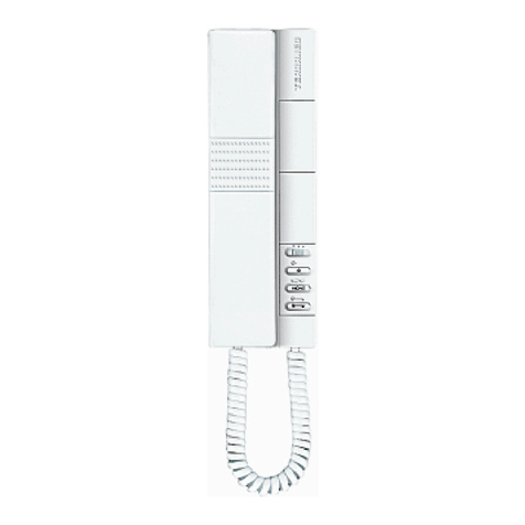
Videocitofono in materiale termoplastico con microtelefono e schermo
LCD 3,5” a colori . Munito di 4 tasti dedicati alle funzioni principali della
videocitofonia per: apertura serratura, autoaccensione, servizio ausiliario
(luce scale), esclusione suoneria e di 4 tasti supplementari program-
mabili che permettono di attuare fino a 4 funzioni ausiliarie o chiamate
intercomunicanti.
E’ possibile effettuare le regolazioni: del volume suoneria, esclusione
suoneria con l‘attivazione della funzione “Utente assente” e la selezione
del tipo suoneria. Possibilità di differenziare le suonerie per le chiamate
da diversi punti, per esempio: targa esterna, chiamata fuoriporta, chia-
mata intercomunicante.
Segnalazioni tramite LED di “porta/cancello aperto” e di “Chiamate senza
risposta” (fino a 4 chiamate, con videocitofono in condizione di suoneria
esclusa).
Da utilizzare in sistemi Due Fili Plus con alimentatore art. 6922.
L’articolo 7529/D è dotato di funzione per portatori di apparecchi acustici.
Prima di procedere alla programmazione leggere attentamente le
istruzioni per avere un quadro completo sulle caratteristiche, fun-
zioni e prestazioni.
Caratteristiche tecniche
• VideocitofonodaesternopareteinABSconfinituralucidaaspecchio
sul frontale.
• Predispostoperinstallazionedaesternopareteconpiastra in metallo
di aggancio per il fissaggio alla parete o ad una scatola (applicabile
direttamente al muro con tasselli oppure ad una scatola da incasso
rettangolare unificata 3 moduli tipo Vimar V71303 o scatole da incasso
rotonde da 60 o 70 mm).
• DisplayLCD3,5”.
• Tastieraasfioramentoconsimboliretroilluminati(infunzionamento).
• AlimentazionedabusDueFili.
• Assorbimento:
-instandby:7mA
-correntemassimainconversazione:150mA
-correntedipiccolimitataaltempodichiamata:200mA
• Temperatura di funzionamento: 0° ÷ 40°C
• Suoneria elettronica: con diversificazione delle melodie tra chiamata
da targa, intercomunicante e fuoriporta.
• Le suonerie sono selezionabili tra 10 melodie diverse.
• UscitapersuoneriasupplementareArt.860Aorelèart.0170/101.
• Ingressoperchiamatafuoriporta.
• IngressoperalimentazionesupplementareArt.6923.
• Dimensionivideocitofono:160x180x45mm
Pulsanti
Fig. 1
A
C
D
B
E1 E2 E3 E4
I
2
Il manuale istruzioni è scaricabile dal sito www.vimar.com

Morsettiera di collegamento:
1, 2 Due coppie di morsetti per bus Due Fili.
E+, E- Alimentazione supplementare per monitor con alimentatore Art.
6923.
12V Collegamento suoneria supplementare (riferimento positivo 12V).
CH Collegamento suoneria supplementare (ripetizione di chiamata).
FP Ingressoper pulsante di chiamata fuoriporta (con riferimento al mor-
setto M).
MRiferimento massa.
BInfunzionamentonormale:
- Luce lampeggiante: segnala che il videocitofono sta
ricevendo una chiamata (da targa esterna o da appare-
cchio intercomunicante).
- Luce fissa: suoneria esclusa (funzione utente assente).
- Luce fissa con lampeggio ogni 10s: a suoneria es-
clusa se sono state inviate chiamate dalla targa, il LED
lampeggia con un numero pari alle chiamate ricevute
dalla targa (rimangono memorizzate fino a 4 chiamate).
Ilresetdellamemorizzazionedeilampeggiavvieneal
ripristino del volume della suoneria.
Infunzionamentoprogrammazione:
- Luce lampeggiante: segnala che si è in stato di pro-
grammazione.
CInfunzionamentonormale:
- Luce fissa: segnalazione di porta aperta se almeno in
una targa è stato installato il sensore e collegato tra i
morsettiPAeM.
Infunzionamentoregolazione:
- Luce lampeggiante: segnala che il citofono è in fase
di regolazione del volume della suoneria o scelta della
melodia.
Segnalazioni:
Regolazioni
HRegolazione della luminosità: consente di variare la lu-
minosità dello schermo.
IRegolazione del contrasto:
consente la regolazione del
contrasto.
LRegolazione del colore:
consente la regolazione del co-
lore.
M
RESET
2
1
1
2
E+ E-
12V CH FP M
C
50Ω
B
100Ω
A
OPEN
PROG
IH
Fig. 2
L
Dip-SwitchperlaterminazioneBus
Morsettiera di collegamento
3
I

Funzionamento
Attenzione: per il funzionamento del videocitofono è necessario che sia
stataeffettuata laprogrammazione dell’identificativoID. Perverificare,
premere un tasto del videocitofono: se al videocitofono è stato assegnato
unID,premendounpulsanteverràemessoun“bip”,senonèstatoasseg-
natonessunIDoèstatocancellato,emetteràuntriplo“bip”.
Tempi di funzionamento
Iltempodirispostaediconversazionedipendonodallaconfigurazionedei
relativi parametri della targa (per modificare questi tempi fare riferimento
alle istruzioni dell’unità elettronica della targa).
- Tempo di risposta (per chiamata da targa): Valore default 30s
(valore minimo 1s, valore massimo 255s)
- Tempo di risposta (per chiamata intercomunicante): 30s (valore fisso)
- Tempo di conversazione (per chiamata da targa): Valore default 120s
(valore minimo 10s, valore massimo 2550s)
- Tempo di conversazione (per chiamata intercomunicante): Valore default
5 minuti (modificabile in tempo illimitato).
Risposta ad una chiamata
All’arrivodiunachiamatadatargaesternaodaapparecchiointercomu-
nicante, si può rispondere durante o al termine del ciclo di suoneria. Per
rispondere si deve sollevare il microtelefono, per terminare la comunicazi-
one riagganciare.
Ricevere una chiamata fuori porta
Ilvideocitofonopuòesserechiamatodaunpulsantefuoriporta,secolle-
gato ai morsetti M e FPdirettamenteomedianteinterfacciaArt.6120(vedi
varianti di collegamento).
Premendo il pulsante fuoriporta il videocitofono suona con un tono differ-
ente da quello ottenuto con la chiamata da targa esterna o intercomuni-
cante. Per terminare la suoneria sollevare il microtelefono.
Nel caso di chiamata fuoriporta mediante pulsante collegato direttamente
ai morsetti FP e Mdel videocitofono, la durata del ciclo di suoneria dipende
dal tempo di pressione del pulsante per un tempo massimo di 10s.
Inviare una chiamata intercomunicante
Per inviare una chiamata verso un altro interno, è necessario sia stato
programmato uno o più pulsanti (vedi paragrafo “Programmazione dei pul-
santi”).
Per chiamare, sollevare il microtelefono e premere il pulsante program-
mato e riferito all’interno da chiamare. Durante la chiamata il videocitofono
emette un tono in modo da avvertire che la chiamata è in atto oppure, se il
citofono/videocitofono è occupato in altra comunicazione nel videocitofono
chiamante si sentirà un tono che avverte che l’utente chiamato è occupato.
Quando l’interno chiamato risponde, automaticamente si attiva la comu-
nicazione, per terminare la conversazione riagganciare il microtelefono.
La durata massima in conversazione è pari a 5 minuti (di default).
Esclusione della suoneria durante una chiamata (Funzione
“Mute”)
Alricevimentodiunachiamatadatargaesterna,daapparecchiointerco-
municanteodachiamatafuoriportatramitedispositivoArt.6120,èpossi-
bile silenziare la suoneria di chiamata premendo il tasto B.
Comando serratura
Premendo il pulsante serratura (con microtelefono agganciato o in con-
versazione), si invia il comando di apertura serratura alla targa (di default
l’ultima targa chiamante).
Autoaccensione
- Autoaccensione con tasto dedicato (tasto A):
per fare l’autoaccensione e comunicare con la targa master, fare una breve
pressione sul tasto A (autoaccensione) per accendere il monitor e sollevare
il microtelefono per attivare la comunicazione. Per chiudere la comunica-
zione riagganciare.
- Autoaccensione con tasto programmato verso targa specifica:
per fare l’autoaccensione e comunicare con una targa specifica, fare una
breve pressione sul tasto che è stato programmato per chiamare la targa
specifica (vedi paragrafo “Programmazione del pulsante autoinserimento /
autoaccensione verso targa specifica ”).
Chiamata a un centralino portineria
Per effettuare una chiamata ad un centralino portineria (se presente nell’im-
pianto): sollevare il microtelefono e inviare la chiamata premendo il tasto
C(serratura).
Funzione audiolesi (solo per Art. 7529/D)
L’Art.7529/D è dotato di una bobina interna che permette l’utilizzo anche a
portatori di protesi acustica. Per questo tipo di funzionamento, è necessario
commutare l’apparecchio acustico in posizione “T”, tuttavia per un corretto
funzionamento dell’apparecchio acustico, fare riferimento al relativo man-
uale di istruzioni.
Nota: l’eventuale presenza di oggetti metallici o apparecchi elettronici, può
compromettere la qualità del suono percepito sull’apparecchio acustico.
I
4

160 mm
180mm
Montaggio da esterno parete
- Installareilvideocitofonolontanodafontiluminoseedicalore.
- Fissare la piastra di aggancio del videocitofono (Fig. 5): direttamente alla
parete mediante due tasselli oppure ad una scatola da incasso rettan-
golare unificata a tre moduli (tipo Vimar V71303) installata verticalmente
oppure ad una scatola da incasso rotonda (da 60 o 70 mm).Indotazione
vengono forniti: 2 tasselli da utilizzare nel caso di fissaggio direttamente
a parete e due viti da utilizzare nel caso di fissaggio su scatola rotonda.
- Si consiglia di installare il videocitofono ad una altezza di 1,40m dal
pavimento al bordo inferiore (Fig. 4).
- Estrarre la morsettiera dal fondo del videocitofono, utilizzando un cac-
ciavite adeguato, facendo attenzione a far leva sui due morsetti estremi
e non sulla scheda elettronica (Fig. 7).
- Eseguire il cablaggio secondo gli schemi di collegamento.
- Ricollegare la morsettiera cablata al videocitofono assicurandosi che sia
premuta fino in fondo.
-Alloggiareilvideocitofononelseguentemodo:posizionareilvideocito-
fono sulla piastra tenendolo leggermente sollevato, a questo punto te-
nendo premuto il frontale fare una leggera pressione verso il basso fino
all’aggancio.
- Nel caso in cui fosse necessario togliere il videocitofono è necessario
agire facendo una leggera pressione nell’apposita levetta (Fig. 6) e sol-
levare (dal basso verso l’alto) in modo da sganciare il videocitofono dal
telaio.
Installazione
Fig. 3
Dimensioni:
1,40 m
Fig. 4
45 mm
Configurazioni
Scelta delle melodie di chiamata
Le suonerie di chiamata sono selezionabili tra 10 diverse melodie e rego-
labili. Sono inoltre distinguibili tra chiamate esterne, intercomunicanti e
fuoriporta (nel caso descritto sotto). La scelta delle melodie viene fatta con
videocitofono in stand-by e microtelefono agganciato.
IlpulsanteperentrareinconfigurazioneèiltastoA (autoaccensione).
IltastoE1permettediselezionarelamelodiaperCHIAMATADATARGA.
IltastoE2permettediselezionarelamelodiaperCHIAMATAINTERCO-
MUNICANTE.
Iltasto E3permettedi selezionarela melodiaper CHIAMATAFUORI-
PORTA(esclusivamenteutilizzandomodulodiinterfacciamentopulsante
Art.6120opulsantedichiamatadapianerottoloVimar).Nelcasodichia-
mata fuoriporta mediante pulsante collegato direttamente ai morsetti FP e
M del videocitofono, la suoneria non può essere cambiata.
Configurazione:
1) Premere il tasto A(autoaccensione) e mantenere premuto (per 2 s), fino
a quando il LED C(serratura), inizia a lampeggiare ed il videocitofono
emette una segnalazione acustica.
2) premere e mantenere premuto il tasto riferito alla suoneria da scegliere
(tasto E1/tasto E2/tasto E3), fino a quando si inizia a sentire la melodia
sul videocitofono.
3) premere ripetutamente il tasto (tasto E1/tasto E2/tasto E3) per selezion-
are il tipo di melodia desiderata.
4) Scelta la suoneria desiderata, per memorizzare premere il tasto Ao non
toccare nessun tasto per 5s. Terminata la configurazione il LED lampeg-
giante si spegne.
Regolazione del volume della suoneria
Ilvolumedellasuoneriaèregolabilesu6livellipiùesclusione.
IlpulsanteperentrareinregolazioneèiltastoA (autoaccensione)
IltastoB(campanella) permette di diminuire il volume della melodia.
IltastoC(chiave) permette di aumentare il volume della melodia.
La regolazione del volume della suoneria viene fatta con videocitofono in
stand-by e microtelefono agganciato.
Configurazione:
1) Premere il tasto Ae mantenere premuto (per 2 s) fino a quando il LED
C(serratura) inizia a lampeggiare ed il videocitofono emette una segnal-
azione acustica.
3) Premere il tasto Bper diminuire, Cperaumentareilvolume.Adogni
pressione corrisponde un livello del volume.
4) Selezionato il volume desiderato, per memorizzare premere il tasto A
o non toccare nessun tasto per 5s. Terminata la configurazione il LED
lampeggiante si spegne e si sente un “bip”.
Esclusione della suoneria (Funzione utente assente)
Con la stessa procedura descritta sopra per la regolazione del volume,
premendo più volte il tasto Bsi arriva a punto in cui la suoneria viene disat-
tivata. Lo stato di “Suoneria esclusa” viene segnalato dall’accensione del
LED di illuminazione tasto B(suoneria esclusa) a luce fissa.
Se con suoneria esclusa il videocitofono riceve una chiamata da targa, il
LED/tasto Blo segnala con un lampeggio per ogni chiamata a cui non è
stato risposto, per un massimo di 4 chiamate (i lampeggi vengono segnalati
ogni10s).Alripristinoalmenodellivellominimodelvolumesuoneria,viene
resettata questa segnalazione.
Manutenzione
Eseguire la pulizia utilizzando un panno morbido. Non versare acqua di-
rettamente sullo schermo e non utilizzare alcun tipo di prodotto chimico.
5
I

Fig. 6
2
1
1
2
E+ E-
12V CH FP M
2
1
1
2
E+ E-
12V CH FP M
Fig. 7
Fig. 5
I
6

M
RESET
2
1
1
2
E+ E-
12V CH FP M
C
50Ω
B
100Ω
A
OPEN
PROG
Programmazioni manuali
Le programmazioni base del citofono/videocitofono sono le seguenti:
- Programmazione dell’identificativo ID, da effettuare sul videocitofono
che riceve la chiamata singolarmente o sul primo videocitofono di un
gruppo di citofoni/videocitofoni con chiamata contemporanea (citofono/
videocitofono capogruppo).
- Programmazione dell’identificativo ID secondario, da effettuare per i
(video)citofoni associati ad un (video)citofono capogruppo.
- Programmazione dei pulsanti programmabili o la modifica della im-
postazione di default di pulsanti supplementari, per servizi ausiliari o
chiamate intercomunicanti.
Le programmazioni devono essere effettuate con l’impianto acceso, senza
comunicazioni attive e solamente dopo aver collegato i citofoni/videocitofoni
all’impianto e programmato le targhe.
N.B: tutte le fasi di programmazione o cancellazione delle stesse, de-
vono essere effettuate con il microtelefono del citofono/videocitofono
sganciato e appoggiato all’orecchio.
Programmazione codice identificativo ID
Ilcodiceidentificativovaprogrammatopermezzodiunatargaprincipale
(MASTER),presentenell’impiantoegiàconfigurata.
Ilvideocitofonovienefornitosenzacodiceidentificativoassociato.Perve-
rificare ciò premere il pulsante serratura e il videocitofono emetterà un se-
gnale acustico (tre beep).
Perprogrammarel’identificativoIDprocederecomesegue:
1) Sollevare il microtelefono.
2) Premere contemporaneamente i tasti Be Ae mantenere premuti i due
tasti fino a quando il LED B(esclusione suoneria) inizia a lampeggiare.
3) Rilasciare i tasti.
4) Premere il tasto Ce tenerlo premuto (per 2 sec.) fino a quando viene
emesso un tono di segnalazione nel microtelefono e si attiva la comuni-
cazione tra il videocitofono e la targa esterna.
5) Rilasciare il tasto C.
Attenzione: sono disponibili 5s per premere il tasto C(come indicato
al punto 4). Se trascorrono i 5s senza premere il tasto C, deve essere
ripetuta la procedura dei punti 1,2,3.
6)Aquestopunto,sonoadisposizionecirca30spereffettuarel’associazi-
onedelcodiceIDdallatargaesterna:
- nelcasoditargaalfanumerica,digitareilcodiceIDprimarioeconfer-
mare con il tasto “campanella”.
- nel caso di targa a pulsanti, premere il pulsante dal quale si desidera
effettuare la chiamata al videocitofono.
Attenzione: se nell’impianto esiste già un citofono/videocitofono con lo
stesso codice identificativo associato, la targa emette un segnale sonoro
basso ed è necessario ripetere l’operazione dall’inizio per assegnare un
codice diverso.
Programmazione codice identificativo ID secondario
La programmazione del codice identificativo secondario è richiesta sola-
mente quando si vuole far suonare contemporaneamente più di un vide-
ocitofonoconlostessopulsanteocodicedichiamata.Ivideocitofoniche
devono suonare contemporaneamente vengono associati ad uno stesso
gruppo.Ilvideocitofonodi“capogruppo”vieneprogrammatoperprimoat-
traverso la precedente procedura “programmazione codice identificativo”,
invece i videocitofoni aggiuntivi del gruppo vengono programmati con il
codice identificativo secondario.
Ilnumeromassimodivideocitofonichesipossonoassociareadunostesso
gruppo,senzal’ausiliodelsoftwareSaveProg,è3piùuncapogruppo.In
alternativa utilizzando il software SaveProg è possibile programmare l’atti-
vazione della suoneria di tutti i videocitofoni e l’accensione del monitor del
solo capogruppo. Prima di rispondere da un videocitofono secondario si
può accendere il relativo monitor tramite il tasto di autoaccensione.
Perprogrammarel’identificativoIDsecondarioprocederecomesegue:
1) Sollevare il microtelefono.
2) Premere contemporaneamente i tasti Be Ae mantenere premuti i due
tasti fino a quando il LED B(esclusione suoneria) inizia a lampeggiare.
3) Rilasciare i tasti.
4) Premere contemporaneamente i tasti Ae Ce mantenerli premuti (per 2
sec.) fino a quando viene emesso un tono di segnalazione nel microtele-
fono e si attiva la comunicazione tra il videocitofono e la targa esterna.
5) Rilasciare i tasti Ae C.
Terminazione Bus per stabilizzazione del segnale
video
Fig. 8B
Nella parte posteriore del videocitofono, vicino alla morsettiera sono pre-
sentiiDip-switchditerminazionedelBUSperlastabilizzazionedelse-
gnale video.
A seconda della configurazione di collegamento (citofoni/videocitofoni
collegati in serie o derivati ad un distributore), settare i dip-swich nella
posizioneadatta(posizioneA,BoC),seguendoleindicazionidescritte
nella nota “Terminazione bus” riportata in seguito, nella sezione schemi
di collegamento.
Dip-Switch per la
terminazioneBus
C
50Ω
B
100Ω
A
OPEN
ON
12
ON
12
ON
12
C
50Ω
B
100
Ω
A
OPEN
ON
12
ON
12
ON
12
C
50Ω
B
100Ω
A
OPEN
ON
12
ON
12
ON
12
Fig. 8A
7
I

5) Premere e tenere premuto il pulsante da programmare (per esempio E1,
E2, E3, E4).
6)Attenderecheilvideocitofonoemettaunsuonocontinuonelmicrotele-
fono.
7) Rilasciare il pulsante da programmare del videocitofono chiamante.
8)Premerenel citofono/videocitofono da chiamare un pulsante (serra-
tura /F1/F2).
9) Un segnale acustico nel microtelefono sul videocitofono (chiamante)
in programmazione conferma che la procedura si è conclusa corretta-
mente.
Procedura per il ripristino dei dati di default per ogni singolo pulsante
(E1, E2, E3, E4)
1) Sollevare il microtelefono.
2) Premere contemporaneamente i tasti Be Ae mantenere premuti i due
tasti fino a quando il LED B(esclusione suoneria) inizia a lampeggiare.
3) Rilasciare i tasti Be A.
4) Premere e tenere premuto il pulsante che si vuole riportare alla pro-
grammazione didefault(nonvalidoperipulsantiAutoaccensione e
Serratura).
5)Attenderecheilvideocitofonoemettaunsegnaleacusticonelmicro-
telefono.
6) Rilasciare il pulsante.
7) Ripremere il pulsante per confermare, il videocitofono emette nuova-
menteunsegnalenelmicrotelefono.Ilpulsanteèorariportatoavalore
di default.
Attenzione: con questa procedura si possono riprogrammare manual-
mente i pulsanti ad esclusione dei tasti serratura e autoaccensione per i
quali è necessario il software SaveProg.
Programmazione del pulsante autoinserimento / autoaccensione
verso targa specifica
(funzione diversa da autoaccensione abilitata dal pulsante “A”)
1) Sollevare il microtelefono.
2) Premere contemporaneamente i tasti Be Ae mantenere premuti i due
tasti fino a quando il LED B(esclusione suoneria) inizia a lampeggiare.
3) Rilasciare i tasti Be A.
4) Premere e tenere premuto il pulsante che si vuole programmare (D, E1,
E2, E3, E4).
5)Attenderecheilvideocitofonoemettaunsuononelmicrotelefono.
6) Rilasciare il pulsante.
7) Chiamare il videocitofono dalla targa su cui si vuole fare l’autoaccensione
diretta:
- Nelle targhe a pulsanti si deve premere il tasto riferito al videocitofono
su cui sto memorizzando il pulsante.
- Nelletarghealfanumeriche,digitareilnumerodell’IDriferitoalvideoc-
itofono su cui sto memorizzando il pulsante e confermare con il pul-
sante campana sulla targa.
8)Alterminedellaprocedurasopradescritta,ilvideocitofonoemetteun
segnale acustico nel microtelefono per indicare che la procedura si è
conclusa correttamente e si accende il monitor.
Procedura di ripristino dei dati di default
1) Sollevare il microtelefono.
2) Premere contemporaneamente i tasti Be Ae mantenere premuti i due
tasti fino a quando il LED B(esclusione suoneria) inizia a lampeggiare.
3) Rilasciare i tasti Be A.
4) Premere nuovamente e mantenere premuto il tasto A.
5) Quando il videocitofono emette una segnalazione acustica nel micro-
telefono, durante il suono, rilasciare il tasto Ae premere brevemente il
tasto C.
Aquestopuntoleprogrammazionidelvideocitofonosonocancellate.Per
prova dell’avvenuta cancellazione della programmazioni, premere il pul-
sante C, il videocitofono deve emettere un segnale acustico nel microtele-
fono.
Attenzione: sono disponibili 5s per premere i tasti Ae C(come indicato
al punto 4). Se trascorrono i 5s senza premere i tasti Ae C, deve essere
ripetuta la procedura dei punti 1,2,3.
6)Aquestopunto,sonoadisposizionecirca30spereffettuarel’associazi-
onedelcodiceIDdallatargaesterna:
- nelcasoditargaalfanumerica,digitareilcodiceIDprimarioeconfer-
mare con il tasto “campanella”.
- nel caso di targa a pulsanti, premere il pulsante dal quale si desidera
effettuare la chiamata al videocitofono.
Attenzione:nellaprogrammazionedell’identificativoIDprimarioesec-
ondario i videocitofoni in programmazione acquisiscono automaticamente
un codice che dipende dall’associazione al pulsante o codice di chiamata
dellatargaesterna.LacorrispondenzatraicodiciIDprimarieirelativiID
secondari è indicata nella tabella riportata in seguito.
Esempio:nelcasovengadatol’identificativoID=8adunsecondocito-
fono/videocitofono, con la procedura di attribuzione dell’identificativo auto-
maticoalsecondocitofono/videocitofono,prenderàautomaticamentel’ID
=72(veditabella).
Quandovieneinviataunachiamataall’ID=8suonerannoentrambiicito-
foni/videocitofoni e si potrà rispondere da entrambi. Se invece digito 72 (nel
casoditargaalfanumerica)checorrispondeall’identificativoIDassegnato
automaticamente dalla procedura, suona e posso rispondere solo dal cito-
fono/videocitofonosucuièstatafattalaproceduradiassegnazionedell’ID
secondario.
Tabella codici ID primari e rispettivi secondari:
ID
Primario
ID Secondario
1 2 3
1 51 52 53
2 54 55 56
3 57 58 59
4 60 61 62
5 63 64 65
6 66 67 68
7 69 70 71
872 73 74
9 75 76 77
10 78 79 80
11 81 82 83
12 84 85 86
13 87 88 89
14 90 91 92
15 93 94 95
16 96 97 98
17 99 100 101
18 102 103 104
19 105 106 107
20 108 109 110
21 111 112 113
22 114 115 116
23 117 118 119
24 120 121 122
25 123 124 125
ID
Primario
ID Secondario
1 2 3
26 126 127 128
27 129 130 131
28 132 133 134
29 135 136 137
30 138 139 140
31 141 142 143
32 144 145 146
33 147 148 149
34 150 151 152
35 153 154 155
36 156 157 158
37 159 160 161
38 162 163 164
39 165 166 167
40 168 169 170
41 171 172 173
42 174 175 176
43 177 178 179
44 180 181 182
45 183 184 185
46 186 187 188
47 189 190 191
48 192 193 194
49 195 196 197
50 198 199 200
Attenzione:percancellarel’appartenenzaadunGruppo,deveessere
usata la procedura di cancellazione delle programmazioni descritta nel
paragrafo “Procedura di ripristino dei dati di default”.
Programmazione dei pulsanti
Attenzione:senza Software SaveProg, è possibile assegnare solo le funzi-
oni di intercomunicanti, autoinserimento targa specifica, riportare al valore
di default i pulsanti che sono stati programmati dall’installatore, ripristino
dei dati di default.
Procedura di programmazione dei pulsanti per eseguire chiamate in-
tercomunicanti
Per programmare i pulsanti procedere come segue:
1) Premere il pulsante “parla/ascolta” o sollevare il microtelefono (a sec-
onda del modello installato)” del citofono/videocitofono da CHIA-
MARE.
2) Sollevare il microtelefono da programmare (chiamante).
3) Premere contemporaneamente i tasti Be Adel videocitofono da pro-
grammare (chiamante) e mantenere premuti i due tasti fino a quando il
LED B(esclusione suoneria) inizia a lampeggiare.
4) Rilasciare i tasti Be A.
I
8

Programmazione con Software SAVEPROG
SaveProgèunsoftwareperPCfornitoindotazionealleinterfacceArt.692I
e692I/U.QuesteinterfaccepermettonoilcollegamentodelPCadunatarga
oadaltrodispositivopredisposto,Art.692ItramiteunaportaRS232mentre
Art.692I/UtramiteconnessioneUSB.
Dopo aver collegato l’interfaccia e installato SaveProg, aprendo il pro-
gramma, appare la finestra seguente.
Aquestosipuòprocedereallaprogrammazioneinduediversemodalità:
1) con 950C virtuale: cliccando sull’icona si apre un’immagine inte-
rattivadelprogrammatoreArt.950Cche permette effettuare le program-
mazionisimulandol’utilizzodelprogrammatoreArt.950C.
2) con le finestre di SaveProg: cliccando sull’icona si apre la finestra
di “Configurazione dispositivi”.
Aquesto puntoè possibile:modificareleprogrammazionidei pulsanti,
creareiGruppi,scegliereitipidimelodieeregolareivolumidellesuonerie,
abilitare e disabilitare funzioni.
Alterminedelleimpostazionidesiderate,sideve:
- salvare cliccando su .
- trasferire il programma nel dispositivo cliccando sull’icona .
Aquestopuntoildispositivoèstatoriprogrammato.
9
I
INFORMAZIONE AGLI UTENTI AI SENSI DELLA DIRETTIVA
2002/96 (RAEE)
Alnedievitaredanniall’ambienteeallasaluteumanaoltreche
di incorrere in sanzioni amministrative, l’apparecchiatura che ripor-
taquestosimbolodovràesseresmaltitaseparatamentedairiutiurbani
ovvero riconsegnata al distributore all’atto dell’acquisto di una nuova. La
raccolta dell’apparecchiatura contrassegnata con il simbolo del bidone
barrato dovrà avvenire in conformità alle istruzioni emanate dagli enti ter-
ritorialmenteprepostiallosmaltimentodeiriuti.Permaggioriinformazioni
contattareilnumeroverde800-862307.
Ilprodottoèconformealladirettivaeuropea2004/108/CEesuc-
cessive.
REGOLE DI INSTALLAZIONE.
L’installazione deve essere effettuata con l’osservanza delle disposizioni
regolanti l’installazione del materiale elettrico in vigore nel Paese dove i
prodotti sono installati.
CONFORMITÀ NORMATIVA.
Direttiva EMC
Norme EN 61000-6-1, EN 61000-6-3.

ASelf-start: for self-start/auto-activation of interphone (to
Master entrance panel by default).
BRingtone muting: Mutes ringtone during call.
CDoor lock: Lock opening command (programming can be
adjusted using the programmer).
DAuxiliary 1 (Stair light): For auxiliary service (actuator 1 of
relay 69RH or 69PH activated by default).
E1 Button 1: Programmable button to activate auxiliary ser-
vice or intercommunicating call (actuator 2 of relay 69RH
or 69PH activated by default).
E2 Button 2: Programmable button to activate auxiliary ser-
vice or intercommunicating call.
E3 Button 3: Programmable button to activate auxiliary ser-
vice or intercommunicating call (entrance panel function F1
activated by default, the last entrance panel to make a call).
E4 Button 4: Programmable button to activate auxiliary ser-
vice or intercommunicating call (entrance panel function F2
activated by default, the last entrance panel to make a call).
Description
Monitor made of thermoplastic material with handset and 3.5” LCD colour
display. Equipped with four buttons for the main video door entry functions:
door lock release, self-start, auxiliary services (stair light), ringtone muting
and 4 programmable supplementary keys that can execute up to 4 auxiliary
functions or intercommunicating calls.
The following settings can be made: ringtone volume, ringtone muting when
“UserAway”functionisactivatedandringtonetypeselection.Optionof
setting different ringtones for calls made from different points, e.g.: outdoor
entrance panel, door call, intercommunicating call.
LED signalling of “door/gate open” and “Unanswered calls” (up to 4 calls
with monitor in ringtone muted state).
For use in Plus Two-Wire systems with power supply 6922.
Article7529/Dhasahearingaidfunction.
Before commencing programming, read the instructions carefully to
get a clear idea of the product’s characteristics, functions and featu-
res.
Technical characteristics
• Surface-mountedmonitormadeofABSwithmirrorglossfinishonfront
panel.
• Designedforexternalwallmountingwithmetalcouplingplateorfittingto
a box (can be mounted directly on the wall using wall plugs or to a Vimar
V71303 type unified 3-module rectangular flush-mount back box or a 60
or 70 mm round flush-mount back box).
• 3.5”LCDdisplay.
• Touch-sensitivekeyswithbacklitsymbols(duringoperation).
• PowersupplyfromTwo-WireBus
• Inputcurrent:
-onstandby:7mA
-maximumconversationcurrent:150mA
-peakcurrentlimitedtocalltime:200mA
• Operatingtemperature:0°÷ 40°C
• Electronicchime:differentringtonesforpanelcall,intercomcallanddoor
call.
• 10differentringtonescanbeselected.
• Outputforadditionalchime860Aorrelay0170/101.
• Inputfordoorcall.
• Inputforadditionalpowersupply(type6923).
• Monitor7529dimensions:160x180x45mm
Buttons
Fig. 1
A
C
D
B
E1 E2 E3 E4
GB
10
The instruction manual is downloadable from the site www.
vimar.com

Connection terminal block:
1, 2 Two pairs of terminals for Two-Wire bus
E+, E- Additionalpowersupplyformonitorwithpowersupplyunittype
6923.
12V Connection of additional chime (positive reference 12V).
CH Connection of additional chime (call repetition).
FP Inputfordoorcallbutton(withreferencetoterminalM).
MEarth reference.
BDuring normal operation:
- Flashing light: indicates that the interphone is receiving
a call (from outdoor entrance panel or from an intercom-
municating device).
- Steady light: ringtone muted (UserAwayfunction).
- Steady light flashing every 10s: if calls have been
made from the entrance panel while the ringtone was
muted, the LED flashes a number of times equal to the
number of calls received from the entrance panel (up to
4 calls are memorised). The flash log is reset when the
ringtone volume is restored.
During programming:
- Flashing light: indicates programming mode.
CDuring normal operation:
- Steady light: indicates that the door is open if the sen-
sor has been installed on at least one entrance panel
andconnectedbetweenterminalsPAandM.
During adjustment:
- Flashing light: indicates that ringtone selection or vol-
ume adjustment is in progress.
Signals:
Settings
HBrightness setting: allows the screen brightness to be
adjusted.
IContrast setting: allows contrast to be adjusted.
LColour setting: allows the colour to be adjusted.
M
RESET
2
1
1
2
E+ E-
12V CH FP M
C
50Ω
B
100Ω
A
OPEN
PROG
IH
Fig. 2 L
Dip-switchforBustermination
Connection terminal block
11
GB

Operation
Important: Forthemonitortowork,theIDmusthavealreadybeenpro-
grammed.Tocheckthis,pressanyofthemonitorbuttons.IfanIDhas
been assigned to the monitor, a beep will sound when a button is pressed;
ifnoIDhasbeenassignedorithasbeendeleted,atriplebeepwillsound.
Operating times
The answer and conversation times depend on the configuration of the
corresponding entrance panel parameters (to change these times, please
refer to the electronic entrance panel unit instructions).
- Answertime(forentrancepanelcall):Defaultvalue30s
(minimum value 1 s, maximum value 255 s)
- Answertime(forintercommunicatingcall):30s(fixedvalue)
- Conversation time (for entrance panel call): Default value 120 s
(minimum value 10 s, maximum value 2550 s)
- Conversation time (for intercommunicating call): Default value 5 minutes
(can be modified to unlimited time).
Answering a call
Acallfromtheoutdoorentrancepanelorfromanintercommunicatingde-
vice can be answered during the chime cycle or once it has ended. To
answer, lift the handset; to end the call, replace the handset.
Receiving a door call
The monitor can receive calls from a door call button if connected to termi-
nals M and FP directly or via interface 6120 (see wiring versions).
When the door call button is pressed, the monitor emits a different tone to
the one used for outdoor entrance panel calls or intercommunicating calls.
To stop the chime, lift the handset.
Inthecaseofadoorcallbymeansofabuttonconnecteddirectlytothe
monitor’s terminals FP and M; chime cycle duration depends on how long
the button was held down (max. 10 s)
Making an intercommunicating call
To make a call to another indoor unit, one or more buttons must have been
programmed(see“Buttonprogramming”section).
To make the call, press the button programmed for the relevant indoor unit.
During the call, the monitor emits a tone in order to signal that the call is
beingmade.Iftheinterphone/monitorisalreadyengagedinanothercall,
a tone will be heard on the monitor making the call to indicate that the user
receiving the call is busy.
When the indoor unit receiving the call answers, communication begins
automatically. Replace the handset to end the conversation.
The maximum conversation time is 5 minutes (default).
Muting the ringtone during a call (Mute function)
When receiving a call from an outdoor entrance panel or from an intercom-
municating device or a door call via device 6120, the call ringtone can be
muted by pressing button B.
Door lock command
Press the lock button (with the handset hooked on or in conversation) to
send a lock opening command to the entrance panel (by default, the last
entrance panel to make a call).
Self-start
- Self-start with dedicated button (button A):
to use the self-start function and communicate with the master entrance
panel,brieflypressbuttonA(self-start)toturnonthemonitorandlift
the handset to start the conversation. Replace the handset to end the
conversation.
- Self-start with programmed button to a specific panel:
to use the self-start function and communicate with a specific entrance
panel, press and release the button programmed to call that entrance
panel (see “Programming the self-activation/self-start button to a specific
panel ” section).
Calling a porter switchboard
To call a porter switchboard (if present in the system): lift the handset and
press button C (lock) to make the call.
Hearing aid function (art. 7529/D only)
Art.7529/Dhasaninternalcoilwhichallowshearingaidwearerstouse
thedevice.Inthisoperatingmode,thehearingaidmustbeswitchedtothe
“T” position. However, for correct operation of the hearing aid refer to its
instruction manual.
Note: metal objects or electronic equipment in the vicinity may affect the
quality of the sound received by the hearing aid.
GB
12

160 mm
180mm
External wall mounting
- Installthemonitorawayfromsourcesoflightandheat.
- Fix the monitor coupling plate: directly to the wall by means of two
expansion plugs or to a unified 3-module rectangular flush-mount back
box (Vimar V71303 type) installed vertically or a round flush-mount
back box (60 or 70 mm). Two expansion plugs to be used for fixing
directly to the wall and two screws for fixing to a round flush-mount box
are provided.
- We recommend installing the monitor with its lower edge at a height of
1.40 m from the floor (Fig. 4).
- Remove the terminal block from the bottom of the monitor using a sui-
table screwdriver. Take care to lever the two end terminals and not the
circuit board (Fig. 7).
- Make the connection as shown in the wiring diagrams.
- Reconnect the wired terminal block to the monitor, ensuring that it is
pushed in completely.
- Mount the monitor as follows: position the monitor on the coupling plate
keeping it slightly raised. While keeping the face plate pressed, apply a
light downward pressure until it clicks into place.
- Ifthemonitorneedstoberemoved,pushlightlyintotheslot(Fig.6)and
raise it so as to release the monitor from the frame.
Installation
Fig. 3
Dimensions:
1,40 m
Fig. 4
45 mm
Configurations
Choice of ringtones
10 different ringtones can be selected. Different ringtones can also be set
for outdoor, intercommunicating and door calls (see below). The ringtones
must be selected with the monitor on stand-by and the handset on the hook.
The button for entering configuration mode is button A(self-start).
ButtonE1selectstheringtoneforENTRANCEPANELCALL.
ButtonE2selectstheringtoneforINTERCOMMUNICATINGCALL.
ButtonE3selectstheringtoneforDOORCALL(exclusivelyusingthebut-
toninterfacemodule6120orVimarlandingcallbutton).Inthecaseofa
door call by means of a button connected directly to the monitor’s terminals
FP and M, the ringtone cannot be changed.
Configuration:
1) PressbuttonA(self-start)andholddown(for2s)untiltheLEDC(lock)
begins flashing and the monitor emits an audible signal.
2) Press and hold down the button for the chosen ringtone (button E1/
button E2/button E3) until the ringtone is heard on the monitor.
3) Press the button repeatedly (button E1/button E2/button E3) to select
the desired type of ringtone.
4)Afterchoosingthedesiredringtone,pressbuttonAorrefrainfromtou-
chinganybuttonsfor5stosave.Aftercompletingtheconfiguration,the
LED flashes and then turns off.
Ringtone volume adjustment
The ringtone volume can be set to 6 levels plus mute.
Press button A(self-start) to enter configuration mode.
Press button B(bell) to lower the ringtone volume.
Press button C(key) to increase the ringtone volume.
The ringtone volume must be adjusted with the monitor on stand-by and
the handset on the hook.
Configuration:
1) Press button Aand hold down (for 2 s) until the LED C (lock) begins
flashing and the monitor emits an audible signal.
3) Press button Bto lower or button Cto increase the volume. Each time
the buttons are pressed the volume changes by one level.
4)Afterchoosingthedesiredvolume,pressbuttonAor refrain from tou-
chinganybuttonsfor5stosave.Aftercompletingtheconfiguration,the
flashing LED goes off and a “beep” is emitted.
Muting the ringtone (User Away function)
Using the volume adjustment procedure described above, pressing button
Ba sufficient number of times results in the ringtone being muted. The
“Ringtone muted” status is indicated by the button BLED (ringtone muted)
lighting up steadily.
Ifthemonitorreceivesacallfromtheentrancepanelwhiletheringtoneis
muted, this is indicated by the LED/button Bemitting one flash for each
unanswered call up to a maximum of 4 calls (these flashes occur every 10
s). When the ringtone volume is restored, at least to its minimum level, this
indication will be reset.
Maintenance
Clean the monitor using a soft cloth, which can be dry or slightly dampened
with water. Do not pour water directly onto the screen and do not use any
type of chemical product.
13
GB

Fig. 6
2
1
1
2
E+ E-
12V CH FP M
2
1
1
2
E+ E-
12V CH FP M
Fig. 7
Fig. 5
GB
14

M
RESET
2
1
1
2
E+ E-
12V CH FP M
C
50Ω
B
100Ω
A
OPEN
PROG
Bus termination for video signal stabilisation
TheBUSterminationdip-switchesforvideosignalstabilizationarelocated
in the rear of the monitor, near the terminal block.
Depending on the connection configuration (interphones/monitors con-
nected in series or derived from a distributor), set the dip-switches in the
appropriateposition(positionA,BorC)accordingtotheinstructionsgiven
inthenote“Bustermination”inthewiringdiagramssectionbelow.
Dip-switch for
Bustermination
Manual programming
Basicinterphone/monitorprogrammingisasfollows:
- Programming ID, which must be performed on the monitor that recei-
ves the call individually or on the first monitor of a group of interphones/
monitors with simultaneous calls (master interphone/monitor).
- Programming secondary ID, which must be done for interphones/mo-
nitors associated with a master interphone/monitor.
- Programming programmable buttons or changing the default setting
of supplementary buttons, for auxiliary services or intercommunicating
calls.
Programming must be carried out with the system switched on, without
active communication and only after the interphones/monitors have been
connected to the system and the entrance panels have been programmed.
N.B.: all the programming or deletion phases must be performed with the
interphone/monitor handset lifted and held against the user’s ear.
Programming ID identification code
The identification code is programmed by means of a main entrance panel
(MASTER),alreadyconfiguredandpresentinthesystem.
The monitor is supplied without associated identification code. To verify
this, press the lock release button and the monitor should emit an audible
signal (triple beep).
To program the ID, proceed as follows:
1) Lift the handset.
2) Press buttons Band AsimultaneouslyandholdthemdownuntilLEDB
(ringtone mute) begins flashing.
3) Release the buttons.
4) Press button Cand hold it down (for 2 sec.) until the handset emits an
audible signal and communication between the monitor and the outdoor
entrance panel begins.
5) Release button C.
Important: you will have 5 s in which to press button C (as indicated in
step4).IfbuttonCis not pressed within the 5 s, steps 1, 2 and 3 must
be repeated.
6)Younowhaveapprox30secondstoassigntheIDcodeoftheexternal
entrance panel:
- inthecaseofanalphanumericpanel,keyintheprimaryIDandpress
the “bell” button to confirm.
- in the case of a push-button entrance panel, press the button you want
to use to call the monitor.
Important:Ifthesystemalreadycontainsaninterphone/monitorwiththe
same associated identification code, the entrance panel emits a low tone
and the process must be repeated from the start in order to assign a dif-
ferent code.
Programming secondary ID
ProgrammingthesecondaryIDisonlynecessarywhenyouwantmorethan
one monitor to ring in response to the same pushbutton or call code. The
monitors that are to ring at the same time are associated with the same
group. The “master” monitor is programmed first by means of the “identifi-
cation code programming” procedure described above, while the additional
group monitors are programmed with the secondary identification code.
The maximum number of monitors that can be associated with the same
groupwithoutusingSaveProgsoftwareis3plusamasterunit.Alternati-
vely, a SaveProg software can be used to program activation of the ringtone
ofallMonitorsandthemonitorofonlythemasterunit.Beforeanswering
from a secondary Monitor, the relevant monitor can be turned on by means
of the self-start button.
Fig. 8B
C
50Ω
B
100
Ω
A
OPEN
ON
12
ON
12
ON
12
C
50
Ω
B
100Ω
A
OPEN
ON
12
ON
12
ON
12
Fig. 8A
C
50Ω
B
100Ω
A
OPEN
ON
12
ON
12
ON
12
15
GB

ToprogramthesecondaryID,proceedasfollows:
1) Lift the handset.
2) Press buttons Band AsimultaneouslyandholdthemdownuntilLEDB
(ringtone mute) begins flashing.
3) Release the buttons.
4) Press buttons Aand Csimultaneously and hold them down (for 2 sec.)
until the handset emits an audible signal and communication between
the monitor and the outdoor entrance panel begins.
5) Release buttons Aand C.
Important: youwillhave5sinwhichtopressbuttonsAandC(asindi-
catedinstep4).IfbuttonsAandCarenotpressedwithinthe5s,steps
1, 2 and 3 must be repeated.
6)Younowhaveapprox30secondstoassigntheIDcodeoftheexternal
entrance panel:
- inthecaseofanalphanumericpanel,keyintheprimaryIDandpress
the “bell” button to confirm.
- in the case of a push-button entrance panel, press the button you want
to use to call the monitor.
Important: WhenprogrammingtheprimaryandsecondaryID,themonitors
undergoing programming automatically acquire a code that depends on the
association with the button or code used to call the outdoor entrance panel.
CorrespondencebetweentheprimaryIDandtherespectivesecondaryID
codes is provided in the table below.
Example:IfID=8isgiventoasecondinterphone/monitor,theautomatic
second interphone/monitor identification attribution procedure will automa-
ticallyassumeID=72(seetable).
WhenacallismadetoID=8,bothmonitors/interphoneswillchimeand
bothcanbeusedtoanswer.If,ontheotherhand,inthecaseofanalphanu-
mericpanelyouenter72(theIDautomaticallyassignedbytheprocedure),
achimeisemittedbytheinterphone/monitorforwhichthesecondaryID
assignation procedure was carried out and only this interphone can be used
to answer the call.
Table of primary and corresponding secondary ID codes:
ID
Primario
ID Secondario
1 2 3
1 51 52 53
2 54 55 56
3 57 58 59
4 60 61 62
5 63 64 65
6 66 67 68
7 69 70 71
872 73 74
9 75 76 77
10 78 79 80
11 81 82 83
12 84 85 86
13 87 88 89
14 90 91 92
15 93 94 95
16 96 97 98
17 99 100 101
18 102 103 104
19 105 106 107
20 108 109 110
21 111 112 113
22 114 115 116
23 117 118 119
24 120 121 122
25 123 124 125
ID
Primario
ID Secondario
1 2 3
26 126 127 128
27 129 130 131
28 132 133 134
29 135 136 137
30 138 139 140
31 141 142 143
32 144 145 146
33 147 148 149
34 150 151 152
35 153 154 155
36 156 157 158
37 159 160 161
38 162 163 164
39 165 166 167
40 168 169 170
41 171 172 173
42 174 175 176
43 177 178 179
44 180 181 182
45 183 184 185
46 186 187 188
47 189 190 191
48 192 193 194
49 195 196 197
50 198 199 200
Important: to delete from a group, the programming deletion procedure de-
scribed in the “Default data restore procedure” section must be performed.
Button programming
Important:withoutSaveProgsoftware,theonlyfunctionsthatcanbeas-
signed are intercommunication, specific entrance panel self-activation, re-
storing buttons programmed by the installer to their default settings and
restoring default data.
Button programming procedure for intercommunicating calls
To program the buttons, proceed as follows:
1) Press the “talk/listen” button or lift the handset (depending on model
installed) for the interphone/monitor TO BE CALLED.
2) Lift the handset to be programmed (the caller handset).
3) Press buttons Band Aon the monitor to be programmed (caller) si-
multaneouslyandholdthemdownuntilLEDB(ringtonemute)begins
flashing.
4) Release buttons Band A.
5) Press and hold down the button to be programmed (e.g. E1, E2, E3, E4).
6) Wait until the monitor handset emits a continuous tone.
7) Release the button to be programmed on the caller monitor.
8)Pressabutton(lock/F1/F2)ontheinterphone/monitor to be called.
9)Anaudiblesignalinthehandsetofthe(caller) monitor being program-
med confirms that the procedure has been completed correctly.
Procedure for restoring default data for each individual button
(E1, E2, E3, E4)
1) Lift the handset.
2) Press buttons Band Asimultaneously and hold them down until LED B
(ringtone mute) begins flashing.
3) Release buttons Band A.
4) Press and hold down the button you want to return to default program-
ming (not valid for Self-start and Lock buttons).
5) Wait until the monitor handset emits an audible signal.
6) Release the button.
7) Press the button again to confirm. The monitor handset will again emit
a signal. The button has now been restored to its default value.
Important: This procedure can be used to manually reprogram all buttons
with the exception of the lock and self-start buttons, for which SaveProg
software is required.
Programming the self-activation/self-start button to a specific
panel
(different from the self-start function enabled using button “A”)
1) Lift the handset.
2)PressbuttonsBandAsimultaneouslyandholdthemdownuntilLEDB
(ringtone mute) begins flashing.
3)ReleasebuttonsBandA.
4) Press and hold down the button to be programmed (D, E1, E2, E3, E4).
5) Wait until the monitor handset emits a tone.
6) Release the button.
7) Call the monitor from the panel you want to perform direct self-start
from:
- Onpush-buttonentrancepanels,pressthebuttoncorrespondingto
the monitor on which the button is being saved.
- Onalphanumericpanels,entertheIDcorrespondingtothemonitor
on which the button is being saved and press the bell button on the
panel to confirm.
8)Attheendoftheproceduredescribedabove,themonitorhandsetemits
an audible signal to indicate that the procedure has been completed
correctly.
Default data restore procedure
1) Lift the handset.
2) Press buttons Band AsimultaneouslyandholdthemdownuntilLEDB
(ringtone mute) begins flashing.
3) Release buttons Band A.
4) Press and hold down button Aagain.
5) While the monitor handset is emitting an audible signal, release button
Aand press button Cbriefly.
The monitor programming has now been deleted. To check that program-
ming has been deleted, press button C; the monitor handset should emit
an audible signal.
GB
16

Programming with SAVEPROG software
SaveProgisaPCsoftwarepackagesuppliedtogetherwithinterfaces692I
and692I/U.TheseinterfacesallowthePCtobeconnectedtoanentrance
panelorothersuitabledevice,type692IviaanRS232portandtype692I/U
viaaUSBconnection.
AfterconnectingtheinterfaceandinstallingSaveProg,onopeningthepro-
gram the following window appears.
Itisnowpossibletoproceedwithprogrammingintwodifferentways:
1) with virtual 950C: clicking on icon opens an interactive image of
t950C programmer, which allows programming to be performed by si-
mulating use of the 950C programmer.
2) with the SaveProg windows: clicking on icon opens the “Device
configuration” window.
Itisnowpossibletochangebuttonprogramming,creategroups,select
ringtone types, adjust ringtone volume and enable or disable functions.
Oncompletingthedesiredsettings:
- save by clicking on .
- transfer the program to the device by clicking on the icon .
The device has now been reprogrammed.
17
GB
ProductisaccordingtoECDirective2004/108/ECandfollowing
norms.
INFORMATION FOR USERS UNDER DIRECTIVE 2002/96
(WEEE)
Inordertoavoiddamagetotheenvironmentandhumanhealthas
well as any administrative sanctions, any appliance marked with
this symbol must be disposed of separately from municipal waste, that is it
mustbereconsignedtothedealeruponpurchaseofanewone.Applianc-
es marked with the crossed out wheelie bin symbol must be collected in
accordance with the instructions issued by the local authorities responsible
for waste disposal.
INSTALLATION RULES.
Installationshouldbecarriedoutobservingcurrentinstallationregulations
for electrical systems in the Country where the products are installed.
CONFORMITY.
EMC directive
Standards EN 61000-6-1, EN 61000-6-3.

AAuto-allumage : insertion automatique/auto-allumage du
moniteur (standard vers la plaque de rue Master).
BExclusion de la sonnerie : Désactive la sonnerie durant
l’appel.
CGâche : commande l’ouverture de la gâche (programma-
tion modifiable avec programmateur).
DAuxiliaire 1 (Éclairage escaliers) : Pour service auxiliaire
(standard, valide l’actionneur 1 du relais 69RH ou 69PH).
E1 Bouton 1 :Boutonprogrammablepourlavalidationdu
service auxiliaire ou appel intercommunicant (standard,
valide l’actionneur 2 du relais 69RH ou 69PH).
E2 Bouton 2 :Boutonprogrammablepourlavalidationdu
service auxiliaire ou appel intercommunicant.
E3 Bouton 3 : Boutonprogrammablepourlavalidationdu
service auxiliaire ou appel intercommunicant (standard,
valide la fonction F1 de la plaque de rue, sur la dernière
plaque de rue ayant effectué l’appel).
E4 Bouton 4 :Boutonprogrammablepourlavalidationduser-
vice auxiliaire ou appel intercommunicant (standard, valide
la fonction F2 de la plaque de rue, sur la dernière plaque
de rue ayant effectué l’appel).
Description
Moniteur en matière thermoplastique avec combiné et écran couleurs LCD
3,5”. Doté de 4 touches dédiées aux fonctions principales du moniteur pour
: ouverture de la gâche, auto-allumage, service auxiliaire (éclairage esca-
liers), exclusion sonnerie et de 4 touches supplémentaires programmables
permettant de valider jusqu’à 4 fonctions auxiliaires ou appels intercom-
municants.
Possibilité d’effectuer les réglages suivants : volume sonnerie, exclusion
sonnerie avec validation de la fonction « utilisateur absent » et sélection du
type de sonnerie. Possibilité de différencier les sonneries pour les appels
depuis plusieurs points, par exemple : plaque de rue, appel du palier, appel
intercommunicant.
Signalisations par LED de « porte/grille ouverte » et « appels sans réponse
» (jusqu’à 4 appels, lorsque la sonnerie du moniteur est exclue).
À utiliser sur les systèmes Deux Fils Plus avec alimentation art. 6922.
L’article 7529/D dispose de la fonction pour porteurs d’appareils acousti-
ques.
Avant de procéder à la programmation, lire attentivement les in-
structions pour connaître toutes les caractéristiques, les fonctions
et les prestations.
Caractéristiques techniques
• moniteurpourmontageensaillieenABS,finitionmiroir.
• Conçupourlemontageensaillieavecplaquedefixationaumurousur
une boîte en métal (se monte directement au mur par chevilles ou sur
une boîte d’encastrement rectangulaire standard 3 modules type Vimar
V71303 ou sur des boîtes d’encastrement rondes 60 ou 70 mm).
• ÉcranLCD3,5”.
• Clavieràeffleurementavecsymbolesrétroéclairés(enmodeallumé).
• AlimentationparBusDeuxFils
• Consommation:
- enmodeveille:7mA
- courant maxi en mode conversation : 150m
- courantdecrêtelimitéàladuréedel’appel:200mA
• Températuredefonctionnement:0°÷ 40°C
• Sonnerieélectronique:avecdiversificationdesmélodiesentreappel
depuis plaque de rue, intercommunicant et palier.
• Possibilitédesélectionnerlessonneriesparmi10mélodiesdifférentes.
• Sortiepoursonneriesupplémentaireart.860Aourelaisart.0170/101.
• Entréepourappelpalier.
• EntréepouralimentationsupplémentaireArt.6923.
• Dimensionsmoniteurart.7529:160x180x45mm
Boutons-poussoirs
Fig. 1
A
C
D
B
E1 E2 E3 E4
F
18
Télécharger le manuel d’instructions sur le site www.vimar.
com

Bornier de raccordement :
1, 2 DeuxpairesdebornespourBusDeuxFils.
E+, E- Alimentationsupplémentairepourmoniteurparalimentationart.
6923.
12V Raccordement sonnerie supplémentaire (référence positif 12V).
CH Raccordement sonnerie supplémentaire (répétition d’appel).
FP Entrée pour bouton d’appel palier (avec référence à la borne M).
MRéférence masse.
BEn mode normal :
- Clignotante :indiquequelemoniteurreçoitunappel
(depuis la plaque de rue ou un appareil intercommuni-
cant).
- Fixe : exclusion de la sonnerie (fonction utilisateur ab-
sent).
- Allumée avec clignotement toutes les 10 s : avec
exclusion de la sonnerie si des appels sont partis de la
plaque de rue, la led clignote le nombre de fois qu’il y
aeud’appelsreçusdepuislaplaquederue(peutmém-
oriser jusqu’à 4 appels). Les clignotements mémorisés
se remettent à zéro après avoir rétabli le volume de la
sonnerie.
En mode programmation :
- Clignotante : indique que l’on est en phase de pro-
grammation.
CEn mode normal :
- Allumée : signale la porte ouverte si au moins une pla-
quederuedisposeducapteurreliéentrelesbornesPA
et M.
En mode réglage :
- Clignotante : indique que le poste est en phase de
réglage du volume de la sonnerie ou du choix de la
mélodie.
Signalisations :
Réglages :
HRéglage de la luminosité : permet de modifier la lumino-
sité de l’écran.
IRéglage du contraste : permet de régler le contraste.
LRéglage de la couleur : permet de régler la couleur.
M
RESET
2
1
1
2
E+ E-
12V CH FP M
C
50Ω
B
100Ω
A
OPEN
PROG
IH
Fig. 2 L
CommutateurpourlaterminaisonBus
Bornierderaccordement
19
F

Fonctionnement
Attention : pour que le moniteur puisse fonctionner, programmer l’identifiant
ID.Pourvérifier,appuyersurunetouchedumoniteur:silemoniteurdispose
d’unID,unbipretentiraenappuyantsurunbouton;s’ilnedisposepasd’un
IDousicelui-ciaétéeffacé,untriplebipretentira.
Temps de fonctionnement
Les temps de réponse et de conversation dépendent de la configuration
des paramètres de la plaque de rue (pour modifier ces valeurs, consulter
les instructions de l’unité électronique de la plaque de rue).
- Temps de réponse (pour appel depuis plaque de rue) : Valeur par
défaut 30 s
(valeur minimum 1 s, valeur maximum 255 s)
- Temps de réponse (pour appel intercommunicant) : 30 s (valeur fixe)
- Temps de conversation (pour appel depuis plaque de rue) : Valeur par
défaut 120 s
(valeur minimum 10 s, valeur maximum 2550 s)
- Temps de conversation (pour appel intercommunicant) : Valeur par
défaut 5 minutes (modifiable en temps illimité).
Réponse à un appel
Lorsqu’un appel arrive d’une plaque de rue ou d’un poste intercommuni-
cant, il est possible de répondre durant ou à la fin du cycle de sonnerie.
Pour répondre, soulever le combiné ; le reposer pour terminer la commu-
nication.
Recevoir un appel de palier
Le moniteur peut être appelé depuis un bouton de palier, s’il est relié aux
bornes M et FP, directement ou via l’interface art. 6120 (voir variantes de
raccordement). En appuyant sur le bouton de palier, la sonnerie du moni-
teur est différente de celle qui signale l’appel provenant de la plaque de
rue ou d’un poste intercommunicant. Soulever le combiné pour interrompre
la sonnerie.
En cas d’appel palier via le bouton relié directement aux bornes FP et M
du moniteur, la durée du cycle de sonnerie dépend du temps durant lequel
on a appuyé sur le bouton (temps maxi 10s).
Effectuer un appel intercommunicant
Pour appeler un autre poste interne, une ou plusieurs touches doivent être
programmées à cet effet (voir paragraphe « Programmation des touches
»). Pour appeler, soulever le combiné et appuyer sur la touche program-
mée et se référant au poste interne à appeler. Durant l’appel, le moniteur
émet une tonalité pour signaler l’appel en cours ou, s’il est occupé dans
une autre communication, le poste qui appelle recevra une tonalité signa-
lant cette situation.
Lorsque le poste interne appelé répond, la communication est automati-
quement validée ; pour terminer la communication, raccrocher le combiné.
La durée maximum de conversation est de 5 minutes (par défaut).
Exclusion de la sonnerie durant un appel (Fonction « Mute »)
Lorsqu’un appel arrive d’une plaque de rue, d’un poste intercommunicant
ou du palier à travers le dispositif art. 6120, il est possible d’exclure la son-
neried’appelenappuyantsurlatoucheB.
Commande gâche
En appuyant sur le bouton gâche (avec le combiné raccroché ou en mode
conversation),laplaquederuereçoitlacommanded’ouverturedelagâche
(par défaut, sur la dernière plaque de rue ayant effectué l’appel).
Auto-allumage
- Auto-allumage avec touche dédiée (touche A) :
Pour procéder à l’auto-allumage et communiquer avec la plaque maître,
appuyerbrièvementsurlatoucheA(auto-allumage)pourallumerle
moniteur et soulever le combiné pour permettre la communication. Rac-
crocher pour terminer la communication.
- A
uto-allumage avec touche programmée vers une plaque spécif-
ique : pour procéder à l’auto-allumage et communiquer avec une plaque
de rue spécifique, appuyer brièvement sur la touche qui a été program-
mée à cet effet (voir paragraphe « Programmation du bouton d’auto-in-
sertion/auto-allumage vers la plaque de rue spécifique »).
Appel à un standard
Pour appeler un standard (si l’installation le prévoit) : soulever le combiné
et lancer l’appel en appuyant sur la touche C (gâche).
Fonction avec boucle auditive (uniquement pour art. 7529/D)
L’art. 7529/D est doté d’une bobine interne qui permet son utilisation de
la part de personnes portant des appareils acoustiques. Pour ce type de
fonctionnement, il est nécessaire de commuter l’appareil acoustique sur la
position « T ». Pour ne pas compromettre le fonctionnement de l’appareil
acoustique, consulter sa notice d’utilisation.
Remarque : la présence éventuelle d’objets métalliques ou d’appareils
électroniques peut compromettre la qualité de la réception sur l’appareil
acoustique.
F
20
This manual suits for next models
1
Table of contents
Languages:
Other ETVAX Intercom System manuals

