1
Montageanleitung
Steckverbinder
www Lesen Sie vor Gebrauch die Betriebs-
anleitung. Stellen Sie sicher, dass
die Betriebsanleitung bei Montage,
Inbetriebnahme und Wartungsarbeiten
jederzeit zur Verfügung steht. Archi-
vieren Sie zusätzlich ein gedrucktes
Exemplar der Betriebsanleitung.
Die Betriebsanleitung, die Konfor-
mitätserklärung und weitere Infor-
mationen sind verfügbar unter der
Bestellnummer des Produkts auf
www.euchner.de.
Bestimmungsgemäßer Gebrauch
Beim Anschluss und Betrieb von Steckverbindern,
welche für folgende Nennspannungen geeignet sind:
fWechselspannung: 50 V < U < 1000 V
fGleichspannung: 75 V < U < 1500 V
ist die Niederspannungsrichtlinie 2014/35/EU
anzuwenden.
Dazu gehört das Einhalten der einschlägigen Anfor-
derungen für den Einbau und Betrieb, insbesondere
der folgenden Norm: EN 60204-1.
Allgemeine Sicherheitshinweise
WARNUNG
Lebensgefahr durch unsachgemäße Installation
und unsachgemäßes Betreiben der Steckverbinder.
fKonfektionierung, Montage, elektrischer An-
schluss und Inbetriebnahme muss ausschließlich
durch autorisiertes Fachpersonal mit folgenden
Kenntnissen erfolgen:
- Spezielle Kenntnisse im Umgang mit Steckver-
bindern, unter Berücksichtigung der geltenden
Bestimmungen.
- Kenntnis der geltenden Vorschriften zur Arbeits-
sicherheit und Unfallverhütung.
fBei Betrieb der Steckverbinder im Außenbereich
schützen Sie diese gesondert gegen Umwelt-
einüsse
fWenn Sie diese Hinweise nicht beachten oder
das Produkt unsachgemäß verwenden, können
Personen oder Sachschäden auftreten.
fVerlust der Gesamtfunktion der angeschlossenen
Geräte durch Schäden am Steckverbinder.
fStecken und trennen Sie die Steckverbinder nicht
unter Last.
Wichtig!
Der Anwender trägt die Verantwortung für den
korrekten Anschluss des Steckverbinders und für
eine korrekte Einbindung in das Gesamtsystem.
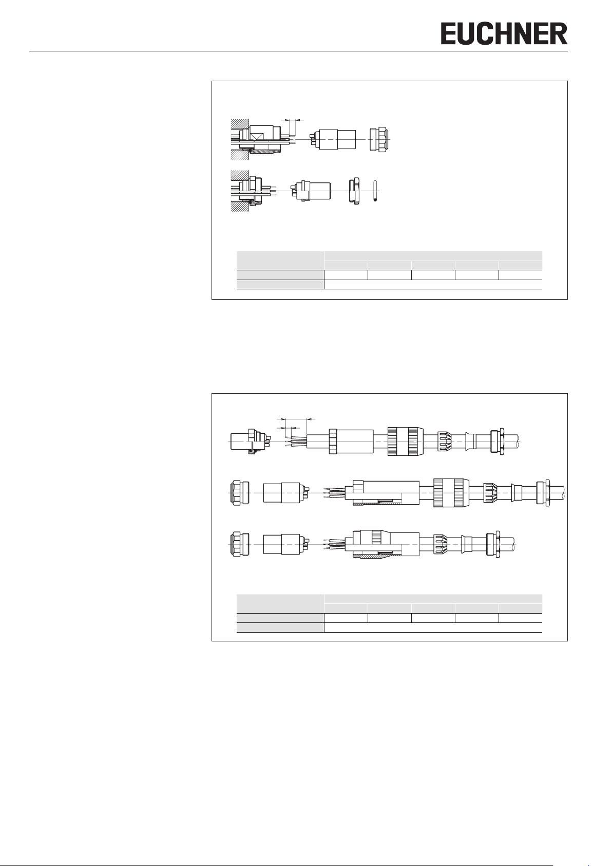
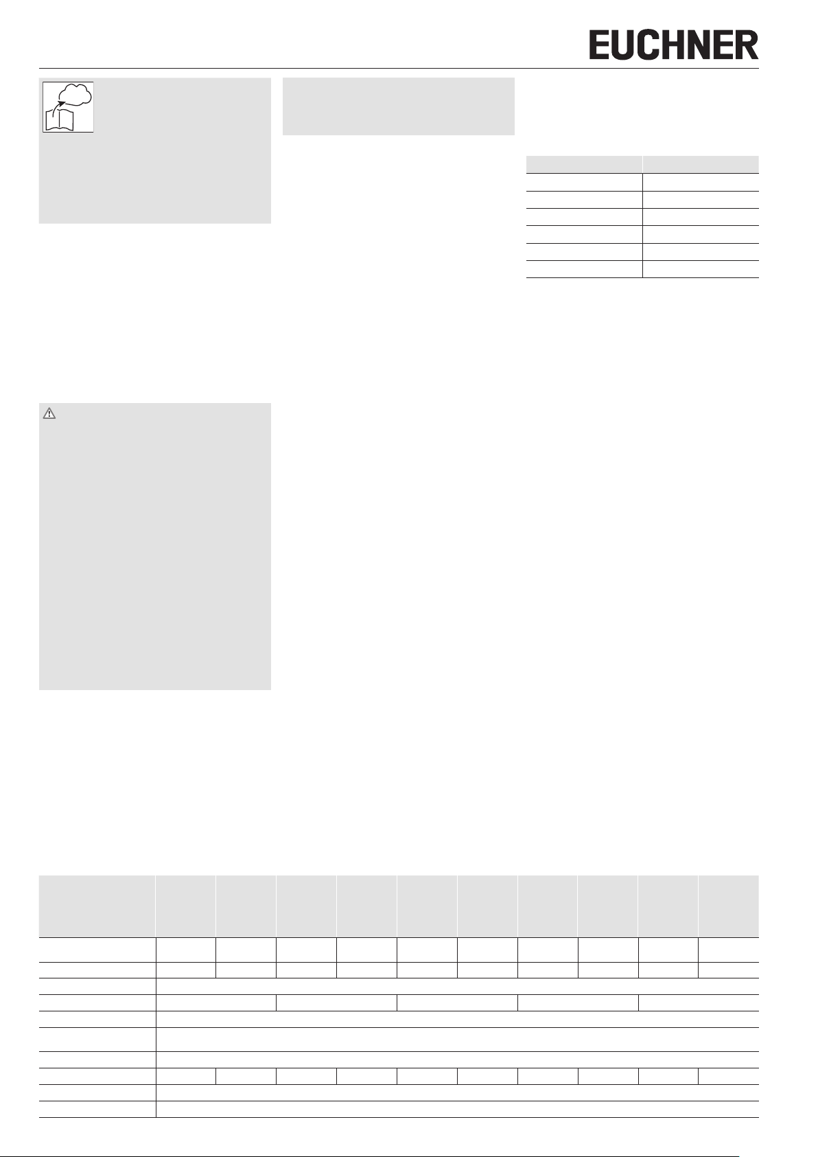
Elektrischer Anschluss
fNehmen Sie nur einwandfreie Produkte in Betrieb.
fBeim Verlegen der Leitung minimalen Biegeradius
beachten.
fBetreiben Sie die Steckverbinder nur im vollständig
gesteckten und verriegelten Zustand.
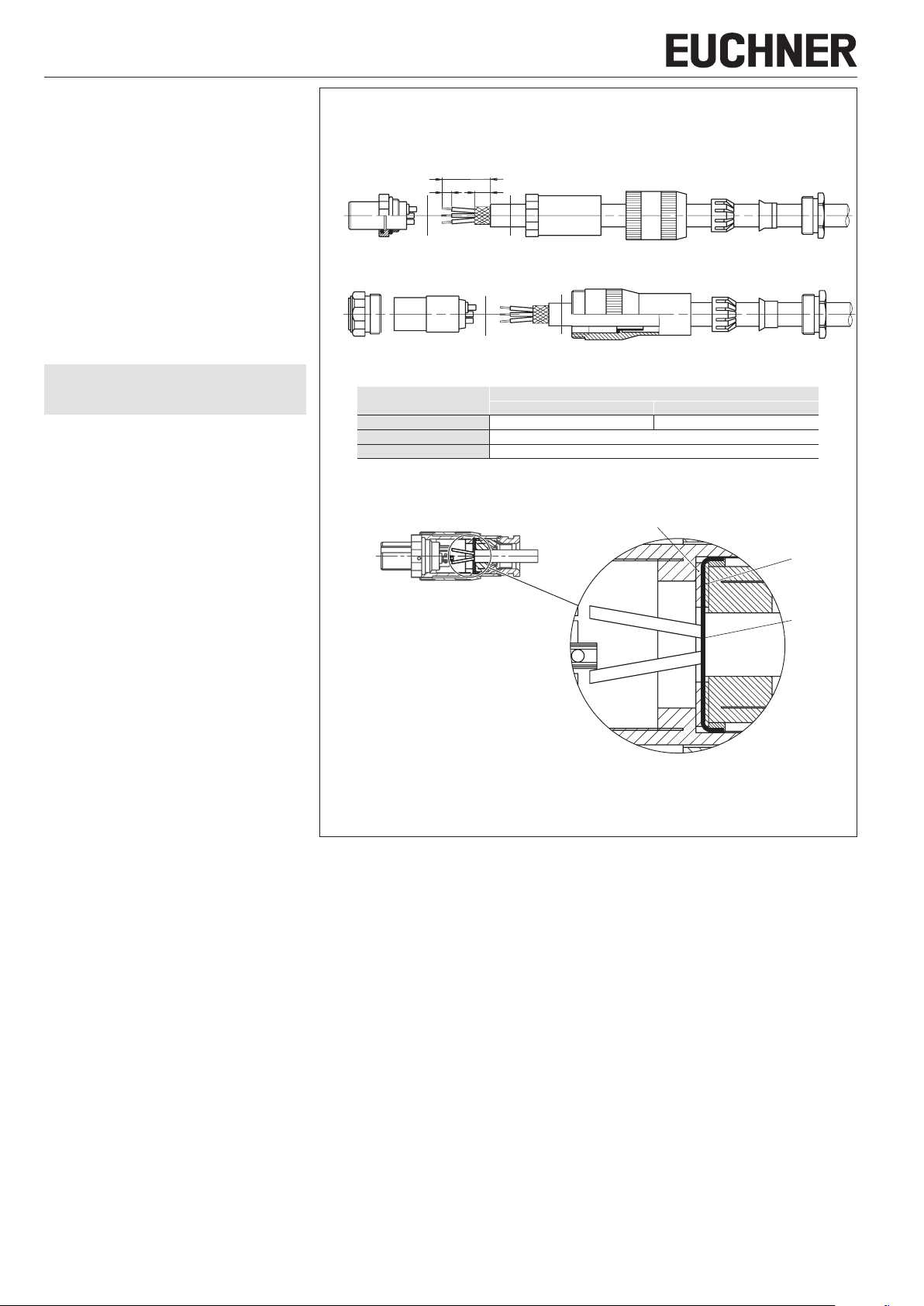
fNach Zusammenbau des Steckverbinders Kabel-
verschraubung fest anziehen.
Kontrolle und Wartung
Um eine einwandfreie und dauerhafte Funktion zu
gewährleisten, sind regelmäßig folgende Kontrollen
erforderlich:
fPrüfen auf Verschmutzungen.
fPrüfen Sie die Produkte regelmäßig auf Beschä-
digungen.
fSetzen Sie beschädigte oder defekte Produkte
sofort außer Betrieb.
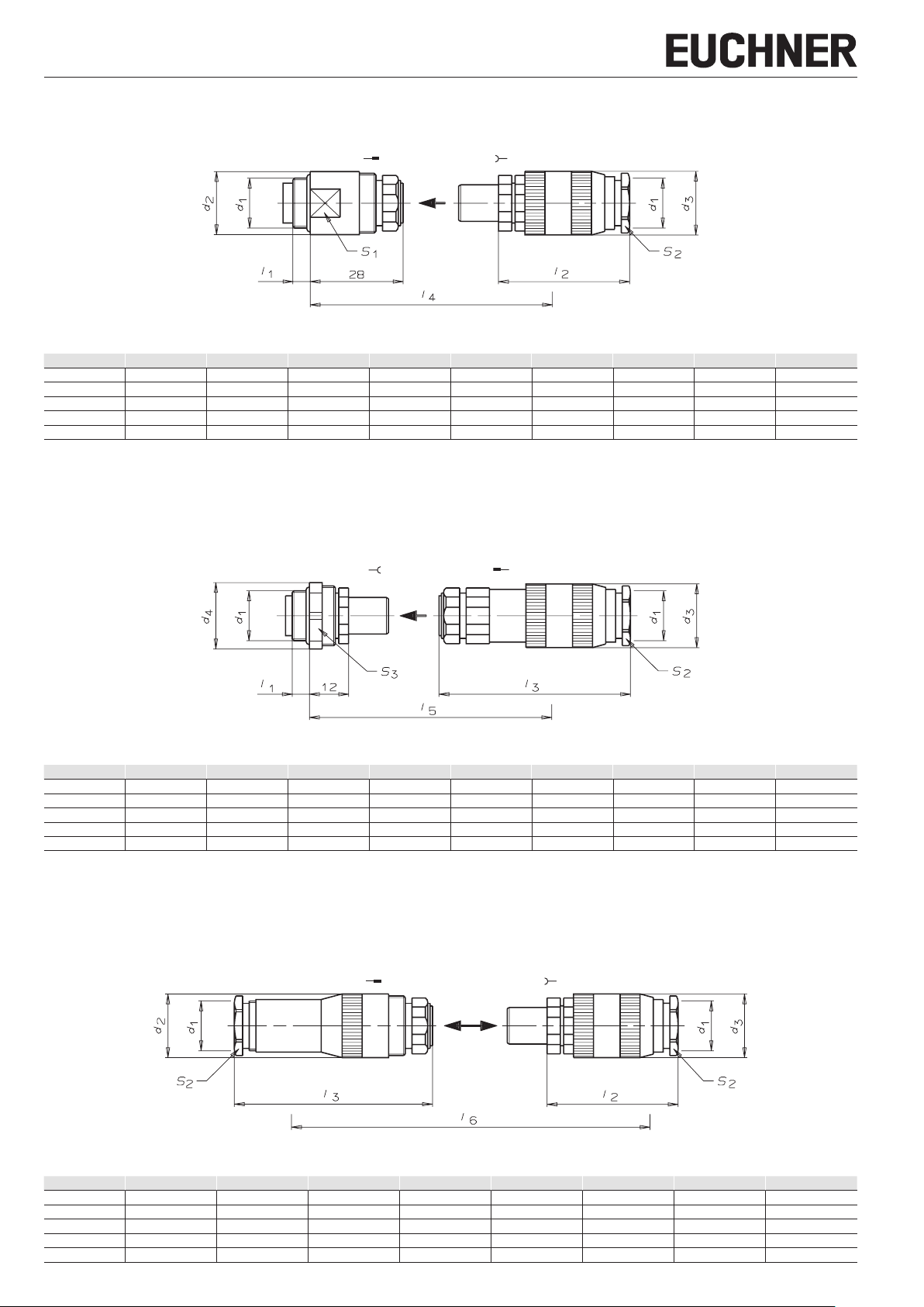
Kombinationsmöglichkeiten von
Steckverbindern
fStift-Dose + Buchsen-Stecker (SD+BS)
fStift-Stecker + Buchsen-Dose (SS+BD)
fKupplungs-Dose + Buchsen-Stecker (KD+BS)
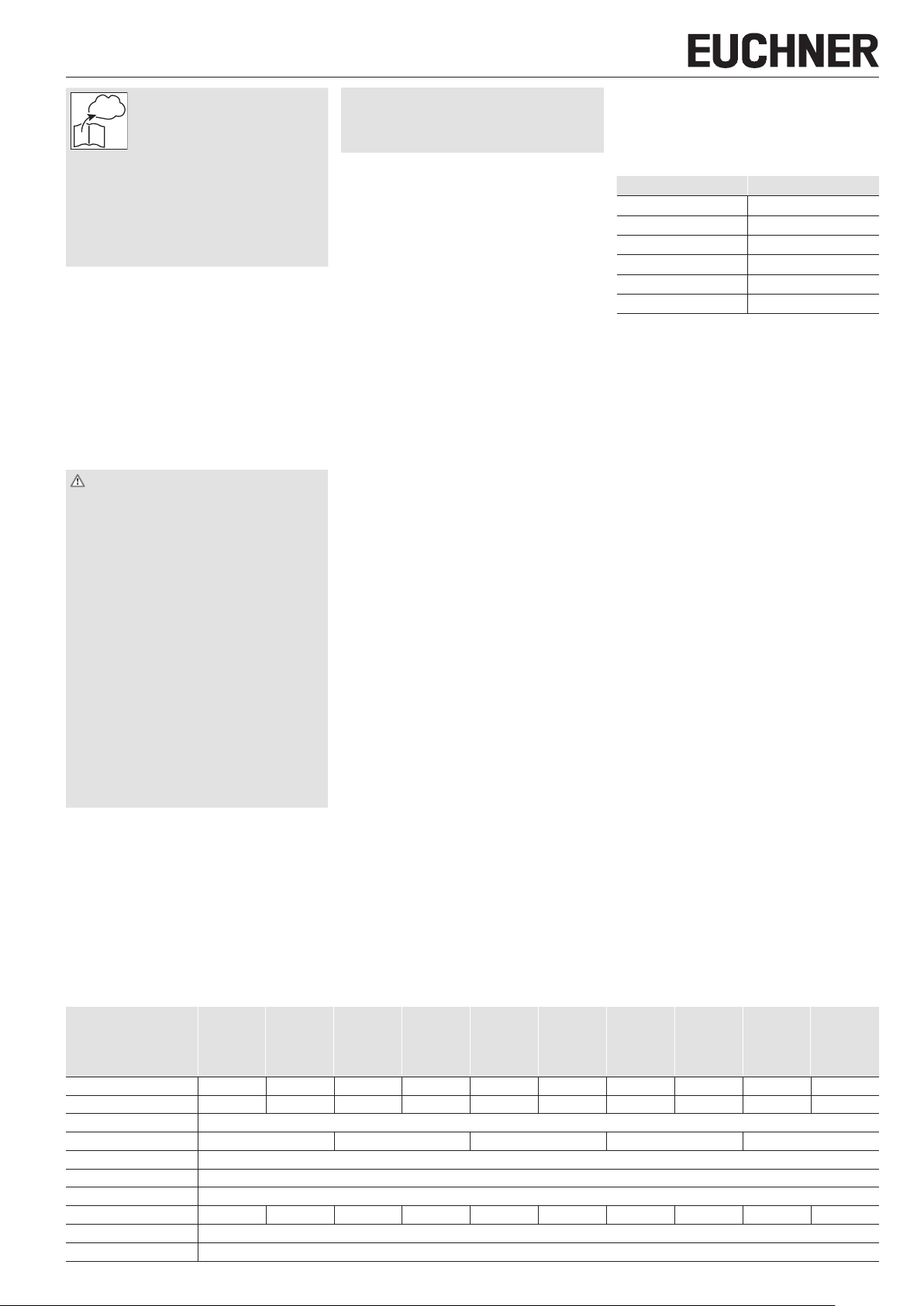
Stecker Dose
BS SD
BS KD
SS BD
BS.K SD.K
BS.K KD.K
SS.K BD.K
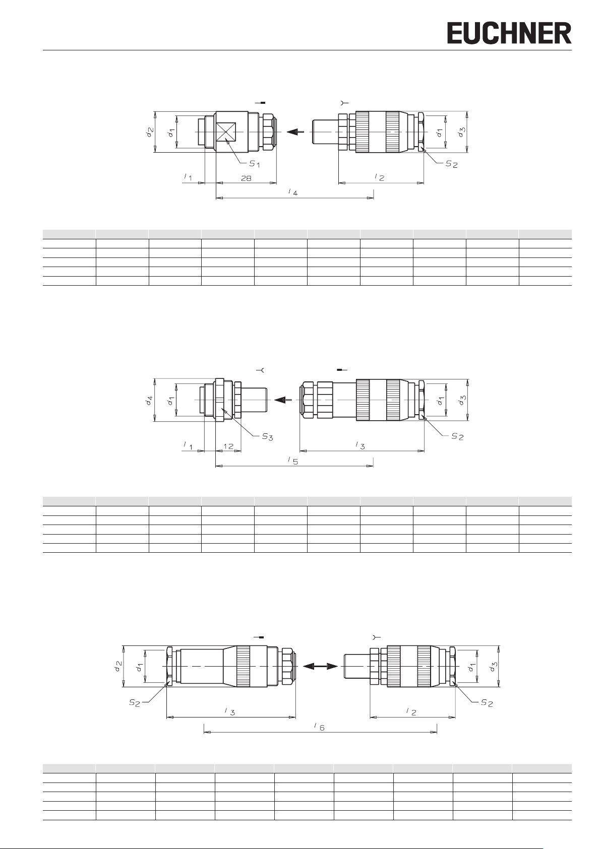
Technische Daten
Bezeichnung BS4
BD4
SD4
SS4
KD4
BS4K
BD4K
SD4K
SS4K
KD4K
BS7
BD7
SD7
SS7
KD7
BS7K
BD7K
SD7K
SS7K
KD7K
BS8
BD8
SD8
SS8
KD8
BS8K
BD8K
SD8K
SS8K
KD8K
BS12
BD12
SD12
SS12
KD12
BS12K
BD12K
SD12K
SS12K
KD12K
BS19
BD19
SD19
SS19
KD19
BS19K
BD19K
SD19K
SS19K
KD19K
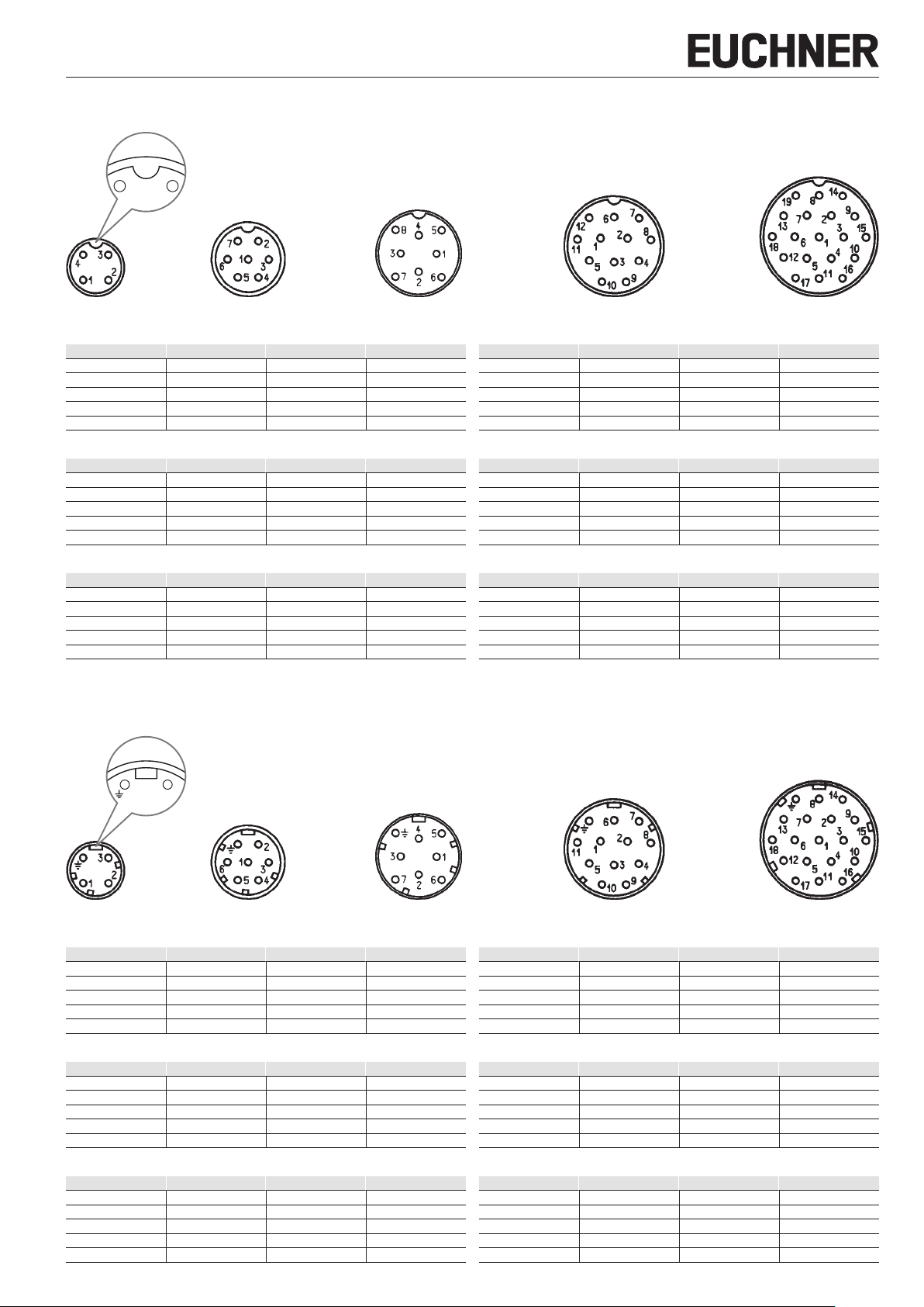
Ausführung mit Schutzleiter ohne Schutzleiter mit Schutzleiter ohne Schutzleiter mit Schutzleiter ohne Schutzleiter mit Schutzleiter ohne Schutzleiter mit Schutzleiter ohne Schutzleiter
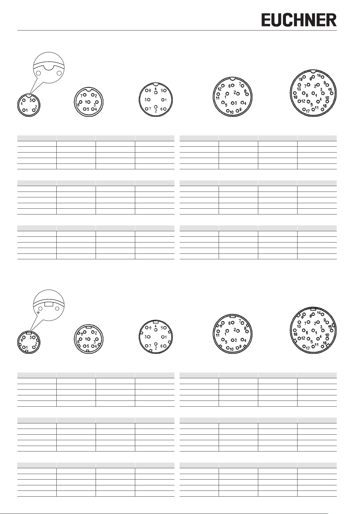
Polzahl 3+PE 46+PE 77+PE 811+PE 12 18+PE 19
Aderquerschnitt max. 1 mm²
Leitungsdurchmesser 6…8 8…10 10…12 12…14 14…18
Kontaktanschlussart Lötanschluss
Schutzart Gehäuse (gesteckt) IP67
Bemessungsstrom 6A
Bemessungsspannung 250V 50V 250V 50V 250V 50V 250V 50V 250V 50V
Bemessungsstoßspannungsfestigkeit 4kV
Durchgangswiderstand 5mΩ