ELEKTRA VCDR User manual

www.elektra.eu
ELEKTRA VCDR
Heating
Cables
Instrukcja montażu PL
Installation manual UK
Инструкция по монтажу RU


Applications
ELEKTRA VCDR heating cables with controller
are intended for prevention of snow and ice
deposition on:
• gutters,
• downpipes,
• roofs,
• roof troughs.
Anti-snow and anti-ice protection system will
prevent:
• water freezing in gutters and downpipes
along with the resulting damages,
• snow and ice accumulation on roofs,
• appearance of damp patches on wall eleva-
tions of buildings,
• icicle formation.
Heat and UV resistant PVC
outer sheath
Tinned copper braiding
PET covered
aluminium foil shield
XLPE insulation
Multi-wire
heating cor
e
VCDR heating cable structure
3

ELEKTRA VCDR
Heating Cables
Characteristics
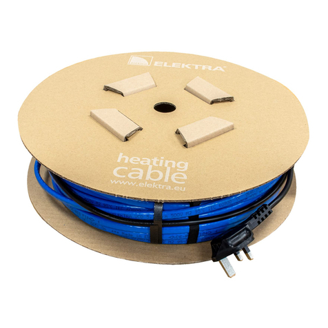
• The heating cables are produced in ready-made
units of the lengths from 9.5 up to 175 m,
• The cables are terminated at one end with
a 4 m-long power supply conductor,
and a connecting joint at the other,
• Specic heat output for VCDR cables: 20 W/m,
• Power supply voltage: 230 VAC, 50/60 Hz,
• External dimensions: ≈5 x 7 mm,
• Min. installation temperature: -5°C,
• Min. cable bending radius: 3.5 D,
• Heating cables are screened, and their mains
connection via a residual current device consti-
tutes effective anti-shock protection,
• Heating cables and power supply conductors’
sheaths are UV resistant.
• “cold tail” power supply conductor
• ELEKTRA VCDR heating cable
• connecting joint between the power supply
conductor and the heating cable
1
2
3
1
2 3
4

Single-side powered
heating cables
Self-adhesive label
Note:
VCDR heating cables are designed for the rated
voltage 230 VAC, 50 Hz.
Heating cables’ heat output may vary with +5%
and -10% from the label values.
!
The label features the following pictograph:
Note:
Never cut the heating cable.
Never trim the heating cable, only the power
supply conductor may be trimmed if required.
Never squash the “cold tail”.
Never bend the joint and end seal.
Do not ever undertake on your own any at-
tempts to repair the heating cables, and in case
any damage is detected, report the damage to
an ELEKTRA authorized installer.
Never stretch or strain the cable excessively, nor
hit it with sharp tools.
Do not install the heating cables when ambient
temperature drops below -5°C.
!
5

ELEKTRA VCDR
Heating Cables
Note:
Heating cables must be installed in accordance
with the instructions.
The mains connections of the heating cable should
be carried out by an authorised electrician.
!
General information
Required heat output selection will depend on
the regional climate conditions.
Ambient
temperature
Heat output
> -5°C -5°C ÷ -20°C -20°C ÷ -30°C < -30°C
Gutters
Downpipes
Roof troughs
Roof edges
2 0 W / m
2 0 W / m
2 0 0 W / m 2
~15 0 W / m 2
2 0 - 4 0 W / m
2 0 - 4 0 W / m
2 0 0 - 2 5 0 W / m
2
~2 5 0 W / m 2
4 0 - 6 0 W / m
2 0 - 4 0 W / m
250-300 W/m2
~300 W/m2
6 0 W / m
4 0 W / m
350 W/m2
~350 W/m2
Roof area
extending
beyond the
building outline
~2 5 0 W / m 2~300 W/m2~350 W/m2~ 5 0 0 W / m 2
Application of the selected heat output
The values given above
refer to a gutter of the
Ø 100-125 mm diameter.
Gutters of larger diameters
require application of
the 20 W/m higher heat
output.
Flat roofs, or when roof
snow barriers are installed,
which would cause
snow deposition, require
increase of the given
values with approx. 15%.
6

Gutter 40 W/m (double-led heating cable)
Downpipe 40 W/m (double-led heating cable)
Gutter 60 W/m (triple-led heating cable)
Downpipe 40 W/m (double-led heating cable)
Examples of VCDR heating cable installation
in gutters and downpipes
Gutter 40 W/m (double-led heating cable)
Downpipe 20 W/m (single-led heating cable)
7

ELEKTRA VCDR
Heating Cables
Controls
For maintenance-free control of the anti-snow
and anti-ice protection system of roofs and
gutters, DIN-bus installed controllers ELEKTRA
ETR2R or ELEKTRA ETOR2 with temperature and
moisture sensors can be applied. The controller
will keep the heating system on standby and
only switch it on when necessary, i.e. both of the
following conditions will be fullled:
• ambient temperature will reach the previously
programmed value (e.g. +1°C),
• moisture sensor will detect snowfall.
ELEKTRA ETR2R controller – max. load up to 16 A
(total output of installed heating cables must not
exceed 3600 W)
ELEKTRA ETOR2 controller – max. load up to
3x 16 A – two moisture sensors can be connected,
8

suitable for controlling two different roof zones
(for applications in extended heating systems).
Controllers are equipped with:
• ETF-744 air temperature sensor,
• ETOR-55 moisture sensor.
9

ELEKTRA VCDR
Heating Cables
Stage 1
Installation in gutters
and downpipes
Preliminary proceedings:
• measure the length of gutters and down-
pipes,
• assess the required heat output resulting
from the climate conditions in which the
installation is to be made,
• select the proper length of the heating cable
taking into account the number of the cable’s
segments in the gutter and downpipe.
Heating cable xing in gutters and downpipes
Heating cables should be xed in order to main-
tain steady spacing between neighbouring ca-
ble’s segments. The segments must not touch or
cross.
Gutters
Heating pipes can be xed with holders (holder
spacing should not exceed 30 cm) or a wire with
clips.
Note:
If the water from downpipes is discharged directly
to the rain channel, the segment of the downpipe
from the surface level to the soil freezing depth
also should be heated.
If the calculated heating cable length has no
direct equivalent in the available ready-made
units, select the longer cable and lead excess
cable in the pipe.
!
10

Gutter holder
Gutter spacing wire with clips
Cable xing in the gutter
with a wire with clips
11

ELEKTRA VCDR
Heating Cables
Downpipes
Single-led heating cables – do not require xing if
the length of the heated downpipe does not exceed
6 m.
Double-led heating cables – to be xed with holders
(holder spacing should not exceed 40 cm) or a wire
with clips. Wire with clips are applied when the
length of the heated downpipe exceeds 6 m.
Downpipe spacing clip
Downpipe spacing wire with clips
Leading the cables
in gutters and downpipes
12

Protect the joining spot of the gutter and
downpipe with a exible cable support to prevent
possible damage to the cable.
When using the wire with clips in the downpipe,
suspend it on the support bar.
• support bar
• exible cable support
1
2
1
2
13

ELEKTRA VCDR
Heating Cables
Installation on roofs
and in roof troughs
In regions of intense snowfall, gutter or down-
pipe heating will not ensure complete removal of
snow and ice. It is necessary to warm up the roof
edge adjoining the gutter, at the width of approx.
50 cm. Especially roof valleys and drains are vu-
berable to snow deposition.
Roofs
Heating cables need to be xed to the roof sur-
face with copper or titanium zinc installation
holders.
If the roof covering is metal sheet, the holders
can be:
• glued to the roof surface,
• xed with screws (xing spots needs to be
carefully sealed with silicone),
• suspended on the insulated structural wire.
14

If the roof covering is tiles, the holders can be:
• xed to the battens,
• xed both to the battens and the structural
wire.
Copper or titanium zinc installation holders
15

ELEKTRA VCDR
Heating Cables
Installation tape underlaid
with a special self-adhesive tape
- tape’s length 50 cm
Roof troughs
Heating cables need to be xed in roof troughs
with aluminium installation tape underlaid
with self-adhesive tape (modied acrylic glue)
used for permanent xing with metal or plastic
surfaces.
Minimal temperature for cable installation is -5°C.
Before xing the installation strip, remove
grease from the metal or plastic surface.
Note:
Spacing between tapes should not drop below
30 cm.
!
Note:
Cable ties must be UV resistant.
!
16

For roof troughs of small gradient (when tape x-
ing to the surface is not necessary), it is possible
to apply plastic installation band.
Plastic installation band
- band’s length 100 cm
Note:
Spacing between bands should not drop below
30 cm.
!
17

ELEKTRA VCDR
Heating Cables
Stage 2
After the heating cable
has been laid:
• stick into the Warranty Card the self-adhesive
label, on the power supply conductor of the
heating cable,
• feed the power supply conductor (“cold tail”)
of the heating cable into the enclosure,
• in case of planned delay in connection of the
heating cable to the electrical installation,
seal the power supply cable of the heat-
ing cable against the possibility of internal
moisture penetration, (e.g. heat shrinkable
end cap),
• perform the measurements of:
- heating core’s resistance,
- insulation’s resistance.
The measurement results of the heating core’s
resistance should not vary from the label value
with more than -5%, +10%.
The heating cable insulation’s resistance, as meas-
ured with an appliance of the rated voltage 1000 V
(megaohmmeter), should not drop below 50 MΩ.
Enter the results into the Warranty Card.
After the cables have been laid, repeat the meas-
urements to check whether the heating cable has
not been damaged during installation works (the
power supply conductor can be extended with
ajunction box or aheat shrink joint set).
18

(brown
or black)
(yellow-green)
Power supply conductors
Ohmmeter
Megaohmmeter
(brown
or black)
(blue)
Heating core’s
resistance measurement
Insulation’s
resistance measurement
19

ELEKTRA VCDR
Heating Cables
Stage 3
Installation of temperature
and moisture sensors
The moisture sensor should be placed at the
bottom of the gutter, on the south facing wall.
The external temperature sensor should be
installed on the north facing wall, not directly
exposed to sunlight.
The air temperature and moisture sensors’ wires
should be fed into the enclosure where the
controller will be positioned.
The sensors’ wires can be extended using a
control cable (the temperature sensor’s wire using
a 2x1.5 mm2-diameter wire, and the moisture
sensor’s wire using a 4x1.5 mm2-diameter wire),
with a heat shrink joint set.
Moisture sensor positioned in the gutter
20
Other manuals for VCDR
1
Table of contents
Languages:
Other ELEKTRA Cables And Connectors manuals
ELEKTRA
ELEKTRA VCD25 User manual

ELEKTRA
ELEKTRA VCD7 User manual

ELEKTRA
ELEKTRA Selftec User manual

ELEKTRA
ELEKTRA TuffTec 30 User manual

ELEKTRA
ELEKTRA SelfTec 16 User manual
ELEKTRA
ELEKTRA VCD25 User manual
ELEKTRA
ELEKTRA VCDR User manual

ELEKTRA
ELEKTRA VCD10 User manual

ELEKTRA
ELEKTRA TuffTec 30 User manual

ELEKTRA
ELEKTRA SelfTec DW User manual