manuals.online logo
Brands
  1. Home
  2. •
  3. Brands
  4. •
  5. EUCHNER
  6. •
  7. Switch
  8. •
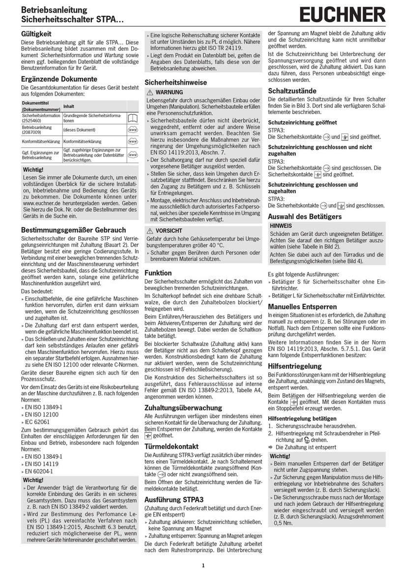
  9. EUCHNER NG Series User manual

EUCHNER NG Series User manual

4
Operating Instructions
Position Switch NG…
Correct use
Position switches series NG are used for posi-
tioning and controlling machines and in industrial
installations.
The built-in switching element with snap-action
function has an NO and an NC contact with double
gap and electrically isolated switching bridge (direct
opening travel 2 x 0.6mm).
Correct use includes compliance with the relevant
requirements for installation and operation, in
particular
fEN60204-1
fENISO12100
Incorrect use
Position switches with switching element ES510
(snap-action switching contact not positively driven)
must not be used in safety circuits.
Mounting
Mounting must be performed only by authorized
personnel.
The position switches must not be used as a
mechanical end stop.
The actuator (arm) can be positively mounted to the
actuating shaft.
The square drives on the actuator and actuating
shaft must engage with each other (see Figure 2a).
Continuously adjustable fastening is possible (inter-
ference t, see Figure 2b).
To ensure correct operation, the trip dog must move
the actuator at least 1mm or 5° beyond the operat-
ing point (see Figure 5 Travel diagrams).
Position switches must be attached and, if nec-
essary, protected in such a way that predictable
damage can be avoided.
It must be ensured that position switches are acces-
sible for maintenance and function tests.
Important!
fTo prevent the actuating element from bouncing,
the dog must run out gradually (see Figure 1).
α

αα
Figure 1: Dog shape
fAdjustment options
Vertical actuator adjustment
Figure 2: Vertical actuator adjustment
Horizontal adjustment 4 x 90°
Figure 3: Horizontal adjustment
Changing the switching direction with lever
arm actuation
Figure 4: Changing the switching direction
Electrical connection
Electrical connection must be performed only
by authorized personnel.
When choosing the insulation material and
wire for the connections, pay attention to the
over-temperature in the housing (depending on
the operating conditions)!
fVersion NG1… (cable entry)
fFit cable gland M20x1.5 with appropriate degree
of protection.
fConductor cross-section 0.34 … 1.5mm².
fFor terminal assignment, see Figure 10.
fTighten screws for connections to the switching
elements to 1Nm.
fCheck that the cable entry is sealed.
fClose switch cover and tighten screws to 1.2Nm.
fVersion NG2… (plug connector SR6)
fConductor cross-section 0.5 … 1.5mm².
fFor connector assignment, see Figure 10a.
fVersion NG2…
(plug connector M12/SVM5)
fConductor cross-section 0.34mm².
fFor connector assignment, see Figure 10b.
Positive mounting 8 x 45°
Continuously adjustable interference t mounting
Figure 2a
45°
90°
Figure 2b
Setup
Function test
fActuate plunger or lever arm and check the
switching function.
Inspection and service
No servicing is required.
Inspection of the following is necessary to ensure
trouble-free long-term operation:
fcorrect switching function
fsecure mounting of all components
fdamage, heavy contamination, dirt and wear
fsealing of cable entry
floose cable connections or plug connectors.
Info: The year of manufacture can be seen in the
bottom, right corner of the type label.
Exclusion of liability and warranty
In case of failure to comply with the conditions for
correct use stated above, or if the safety regula-
tions are not followed, or if any servicing is not
performed as required, liability will be excluded and
the warranty void.
Notes about
For NG2:
For use and applications as per the requirements of
, a class2 power supply or a class2 transform-
er according to UL1310 or UL1585 must be used.
Connection cables for position switches installed at
the place of use must be separated from all moving
and permanently installed cables and un-insulated
active elements of other parts of the system that
operate at a voltage of over 150V. A constant
clearance of 50.8mm must be maintained. This
does not apply if the moving cables are equipped
with suitable insulation materials that possess an
identical or higher dielectric strength compared to
the other relevant parts of the system.
For NG1:
For use and applications as per the requirements
of , copper wire 60/75°C is to be used.
EU declaration of conformity
The declaration of conformity is part of the operating
instructions, and it is included as a separate sheet
with the unit.
The original EU declaration of conformity can also
be found at: www.euchner.com
Service
If servicing is required, please contact:
EUCHNER GmbH + Co. KG
Kohlhammerstraße 16
70771 Leinfelden-Echterdingen
Service telephone:
+49 711 7597-500
Fax:
+49 711 753316
E-mail:
support@euchner.de
Internet:
www.euchner.com
Left / right
switching
(default setting)
Right
switching
Left
switching
5
Operating Instructions
Position Switch NG…
Technical data
Parameter Value
Housing material Anodized die-cast alloy
Degree of protection NG1… cable entry
NG2… plug connector M12/SVM5 NG2… plug connector SR6
IP67 IP65
Mech. life 30 x 106operating cycles
Ambient temperature -25 … +80 °C
Degree of contamination
(external, according to EN60947-1) 3 (industrial)
Installation orientation Any
Approach speed, max. [m/min] HB HS/SB/
SM VB VS RK WO/KO/
DO
RG/RS/
RL/FO
300 60 120 30 50 10 20
Approach speed, min. [m/min] HB/HS WO/KO/RS/
RK/RL/DO
FO/VB/
VS/SB/SM
0.1 0.01 0.5
Actuation frequency 7,000/h (HB/HS = 10,000/h; FO = 6,000/h
Actuating force at 20 °C 15 N
Contact material Silver alloy, gold ashed
NG1… NG2…
Connection
Cable entry M20 x 1.5
Plug connector
Conductor cross-section (exible/rigid) 0.34 … 1.5mm²
0.34 … 0.75mm² with LED indicator SR6: 0.5 … 1.5mm²
NG1…M/NG2…SR6 NZ2…SVM5
Rated insulation voltage
Ui= 250 V Ui= 50 V
Rated impulse withstand voltage Uimp = 2.5 kV Uimp = 1.5 kV
Conditional short-circuit current 100 A
Operating voltage for optional LED indicator L060
12 - 60 V AC/DC
L110
110 V AC ±15%
L220
230 V AC ±15%
Rated data switching element ES510
Switching principle Snap-action contact elements
Utilization category acc. to EN60947-5-1 Cable entry Plug connector
SR61) Plug connector SVM5
AC-12
AC-15
DC-13
Ie10 A Ue230 V
Ie6 A Ue230 V
Ie6 A Ue24 V
-
Ie6 A Ue230 V
Ie6 A Ue24 V
-
Ie4 A Ue30 V
Ie4 A Ue24 V
Short circuit protection (control circuit fuse)
acc. to IEC60269-1 1) See utilization category 6 A gG 4 A gG
Conventional thermal current Ith 1) 6 A 4 A
Switching current, min.
at switching voltage
10 mA
DC 24 V
1) Limitation for NG2… at ambient temperature > 70 … 80°C
NG2…SR6
Utilization category acc. to EN60947-5-1 AC-15
DC-13
Ie2 A Ue230 V
Ie2 A Ue24 V
Short circuit protection (control circuit fuse)
acc. to IEC60269-1
2 A gG
Conventional thermal current Ith 2 A
Operating Instructions
Position Switch NG…
6
Subject to technical modications; no responsibility is accepted for the accuracy of this information. © EUCHNER GmbH + Co. KG 2032310-13-12/19 (Translation of the original operating instructions)
SR6WF
55 13,5
50
75
SR6EF
∅28
60
80
26
∅7 - 9
Figure 5: Travel diagrams
Figure 6: Actuators and approach directions
A
B
C
Free position
A
B
C
End position
End position
Free position
End position
Free position
DO = chisel plunger WO = rounded plunger KO = ball plunger RK = roller plunger roller plunger RL = roller plunger FO = spring actuator
RG = plastic roller
RS = steel roller
End position
Free position
Operating
point
End position
Free position
End position
Free position
End position
Free position
End position
Free position
End position
Free position
XX
66
59
Roller arm switching on both sides
HB = plastic roller (dimension X = 6 mm)
HS = steel roller (dimension X = 5 mm)
Rod arm switching on both sides
SB = plastic rod
SM = aluminum rod
Adjustable roller arm
VB = plastic roller (dimension X = 6 mm)
VS = steel roller (dimension X = 5 mm)
Plug connector SR6
Pin assignment of male socket
(top view of switch mounted connector)
Inserted
Inserted
M = 1,2 Nm
M = 1,8 Nm
M20x1,
5
Plug connector SVM5
(M12, 5-pin)
Pin assignment of male socket
(top view of switch mounted connector)
3
1
4
2
13
21
14
22
56
3
1
4
2
13
21
14
22
4
3
1
2
Terminal assignment
ES 510
with LED indicator
3
1
4
2
13
21
14
22
5
6
3
1
4
2
13
21
14
22
Terminal assignment
ES 510
Figure 10a
Figure 10b
Figure 7: Actuators and approach directions
Figure 8: Dimension drawing of NG1H... with cable entry Figure 9: Dimension drawing of NG2... with plug
connector SR6
Figure 10: Switching elements and
connector assignment
Contacts
open
closed
AOperating point
BEnd position
CReset point

Other EUCHNER Switch manuals

EUCHNER STP-TW Series User manual

EUCHNER

EUCHNER STP-TW Series User manual

EUCHNER CTA-L1/2-BP User manual

EUCHNER

EUCHNER CTA-L1/2-BP User manual

EUCHNER CES-I-BR Series User manual

EUCHNER

EUCHNER CES-I-BR Series User manual

EUCHNER NZ1VZ EX Series User manual

EUCHNER

EUCHNER NZ1VZ EX Series User manual

EUCHNER STP AS1 Series User manual

EUCHNER

EUCHNER STP AS1 Series User manual

EUCHNER CTP-L1/2-BP User manual

EUCHNER

EUCHNER CTP-L1/2-BP User manual

EUCHNER CES-A-F1B-02B-AS1 User manual

EUCHNER

EUCHNER CES-A-F1B-02B-AS1 User manual

EUCHNER CTM-I2-AS2B User manual

EUCHNER

EUCHNER CTM-I2-AS2B User manual

EUCHNER TZ Series User manual

EUCHNER

EUCHNER TZ Series User manual

EUCHNER TZ1LE024RC18VAB-C1828 User manual

EUCHNER

EUCHNER TZ1LE024RC18VAB-C1828 User manual

EUCHNER CTP-I.-AS Unicode Series User manual

EUCHNER

EUCHNER CTP-I.-AS Unicode Series User manual

EUCHNER NM HB Series User manual

EUCHNER

EUCHNER NM HB Series User manual

EUCHNER CTM-CBI-BP User manual

EUCHNER

EUCHNER CTM-CBI-BP User manual

EUCHNER NM VZ Series User manual

EUCHNER

EUCHNER NM VZ Series User manual

EUCHNER NM03HBA-MC1931 User manual

EUCHNER

EUCHNER NM03HBA-MC1931 User manual

EUCHNER ZSB Series User manual

EUCHNER

EUCHNER ZSB Series User manual

EUCHNER STA-BI-3A-2131A024RC18C1826 User manual

EUCHNER

EUCHNER STA-BI-3A-2131A024RC18C1826 User manual

EUCHNER TZ Series User manual

EUCHNER

EUCHNER TZ Series User manual

EUCHNER NM AV Series User manual

EUCHNER

EUCHNER NM AV Series User manual

EUCHNER STP-TW AS1 Series User manual

EUCHNER

EUCHNER STP-TW AS1 Series User manual

EUCHNER TQ Series User manual

EUCHNER

EUCHNER TQ Series User manual

EUCHNER STA Series User manual

EUCHNER

EUCHNER STA Series User manual

EUCHNER TP-TW Series User manual

EUCHNER

EUCHNER TP-TW Series User manual

EUCHNER ZXE User manual

EUCHNER

EUCHNER ZXE User manual

Popular Switch manuals by other brands

Hored S5700-24F-8G-4TF user manual

Hored

Hored S5700-24F-8G-4TF user manual

BD ASM 400 operating manual

BD

BD ASM 400 operating manual

Horstmann ServicePlus S17R User operating instructions

Horstmann

Horstmann ServicePlus S17R User operating instructions

NETGEAR M4100 Series ProSAFE Hardware installation guide

NETGEAR

NETGEAR M4100 Series ProSAFE Hardware installation guide

Wearpai HDSW0021M1 user manual

Wearpai

Wearpai HDSW0021M1 user manual

OZU UM-004 user manual

OZU

OZU UM-004 user manual

Siemens 3TM operating instructions

Siemens

Siemens 3TM operating instructions

Flight Display Systems DAPS440 Installation and operation manual

Flight Display Systems

Flight Display Systems DAPS440 Installation and operation manual

Fortinet FortiSwitchRugged 124D quick start guide

Fortinet

Fortinet FortiSwitchRugged 124D quick start guide

Digitus DN-95104 manual

Digitus

Digitus DN-95104 manual

socomec SIRCO MOT AT instruction manual

socomec

socomec SIRCO MOT AT instruction manual

GE HO97844 instruction manual

GE

GE HO97844 instruction manual

WIKA DC Series instruction manual

WIKA

WIKA DC Series instruction manual

Western Telematic Net Reach RPC-4840N Specifications

Western Telematic

Western Telematic Net Reach RPC-4840N Specifications

Seeed Grove manual

Seeed

Seeed Grove manual

HPE FlexFabric 5940 SERIES Configuration guide

HPE

HPE FlexFabric 5940 SERIES Configuration guide

Flash MONOTRON 300 CS User instruction

Flash

Flash MONOTRON 300 CS User instruction

Extreme Networks ReachNXT 100-8t datasheet

Extreme Networks

Extreme Networks ReachNXT 100-8t datasheet

manuals.online logo
manuals.online logoBrands
  • About & Mission
  • Contact us
  • Privacy Policy
  • Terms and Conditions

Copyright 2025 Manuals.Online. All Rights Reserved.