Euphonix FC727 User manual

Euphonix FC727/726
Digital Audio Format Converter
Operation Manual
Document Revision: 1.3
Part Number: 840-07807-03
Release Date: November, 2003
Euphonix, Inc.
220 Portage Ave.
Palo Alto, California 94306
Phone: 650-855-0400
Fax: 650-855-0410
Web: http://www.euphonix.com
e-mail: [email protected]
FC727
EUPHONIX, INC.
PALO ALTO
MADE IN THE U.S.A.
AES 49-56 AES 41-48 AES 33-40 AES 25-32 AES 17-24 AES 9-16 AES 1-8
SERVICE
IN
IN
AES
SYNC AES SYNC
WORD SYNC
IN OUT
FORMAT B
MADI A MADI B
IN 2 OUT 2
IN 1 OUT 1
IN
CH 49-56 CH 41-48 CH 33-40 CH 25-32
CH 17-24 CH 9-16 CH 1-8
SDIF-2 SYNC
or
SLAVE CLK
OUT
FORMAT A
OUT
VA C FUSE
100-240 1.0-0.5A 2.5A
50/60Hz SLOW
CURRENT
FMT A FMT B
AES STEREO
AES MONO
FMT A AES/FMT B/FMT A
IN THRU
SLAVE CLK
CAUTION: To prevent risk of fire
replace fuse with the same type and rating,

In the interest of continued product development, Euphonix reserves the right to make
improvements in this manual and the product it describes at any time, without notice or
obligation.
System 5, S-5, PatchNet, eMix, EuCon, R-1, Audio Deck, Studio Hub are trademarks of
Euphonix, Inc.
©2003 Euphonix, Inc. All rights reserved worldwide. No part of this publication may be
reproduced, transmitted, transcribed, stored in a retrieval system, or translated into any
language in any form by any means without written permission of Euphonix, Inc.
Manual design by Rob Wenig.
Manual written by Jon Harris and Rob Wenig.

IMPORTANT SAFETY INSTRUCTIONS
The lighting flash with arrowhead symbol within an equilateral triangle, is intended to alert
the user to the presence of uninsulated “dangerous voltage” within the product’s enclosure
that may be of sufficient magnitude to constitute a risk of electrical shock to persons.
The exclamation point within an equilateral triangle, is intended to alert the user to the
presence of important operating and maintenance (servicing) instructions in the literature
accompanying the product.
1) Read these instructions.
2) Keep these instructions.
3) Heed all warnings.
4) Follow all instructions.
5) Do not use this apparatus near water.
6) Clean only with a dry cloth.
7) Do not block any ventilation openings. Install in accordance with the manufacturer’s instructions.
8) Do not install near any heat sources such as radiators, heat registers, stoves, or other apparatus
(including amplifiers) that produce heat.
9) Do not defeat the safety purpose of the polarized or grounding-type plug. A polarized plug has
two blades with one wider than the other. A grounding type plug has two blades and a third
grounding prong. The wider blade or the third prong are provided for your safety. If the provided
plug does not fit into your outlet, consult an electrician for replacement of the obsolete outlet.
10) Protect the power cord from being walked on or pinched particularly at plugs, convenience
receptacles, and the point where they exit from the apparatus.
11) Only use attachments/accessories specified by the manufacturer.
12) Use only with the cart, stand, tripod, bracket, or table specified by the manufacturer, or sold
with the apparatus. When a cart is used, use caution when moving the cart/apparatus combi-
nation to avoid injury from tip-over.

13) Unplug this apparatus during lightning storms or when unused for long periods of time.
14) Refer all servicing to qualified service personnel. Servicing is required when the apparatus has
been damaged in any way, such as power-supply cord or plug is damaged, liquid has been
spilled or objects have fallen into the apparatus, the apparatus has been exposed to rain or
moisture, does not operate normally, or has been dropped.
15) WARNING – TO REDUCE THE RISK OF FIRE OR ELECTRIC SHOCK, DO NOT EXPOSE
THIS APPARATUS TO RAIN OR MOISTURE.
16) Do not expose this equipment to dripping or splashing and ensure that no objects filled with
liquids, such as vases, are placed on the equipment.
17) To completely disconnect this equipment from the AC Mains, disconnect the power supply
cord plug from the AC receptacle.
18) The mains plug of the power supply cord shall remain readily operable.
19) This unit is provided with a power supply cord set suitable for 120V AC input only (for U.S.A.
and Canada). For other than U.S.A. and Canada, a qualified person must provide for use with
this unit, an appropriate, approved power supply cord set which is in compliance with the end
use country requirements and has a minimum cross-sectional area of 1.0mm2.
20) For units with more than one power cord:
Caution: This unit has more than one power supply cord. Disconnect two power supply
cords before servicing to avoid electrical shock.
Attention: Cet appareil comporte plus d’un cordon d’alimentation. Afin de prévenir les
chocs électriques, débrancher les deux cordons d’alimentation avant de faire le
dépannage.
21) Operator Accessible Fuse:
Caution: For continued protection against risk of fire, replace only with same type and
rating of fuse.
Attention: Pour ne pas compromettre la protection contre les risques d’incendie, remplacer
par un fusible de même type et de même caractéristiques nominales.

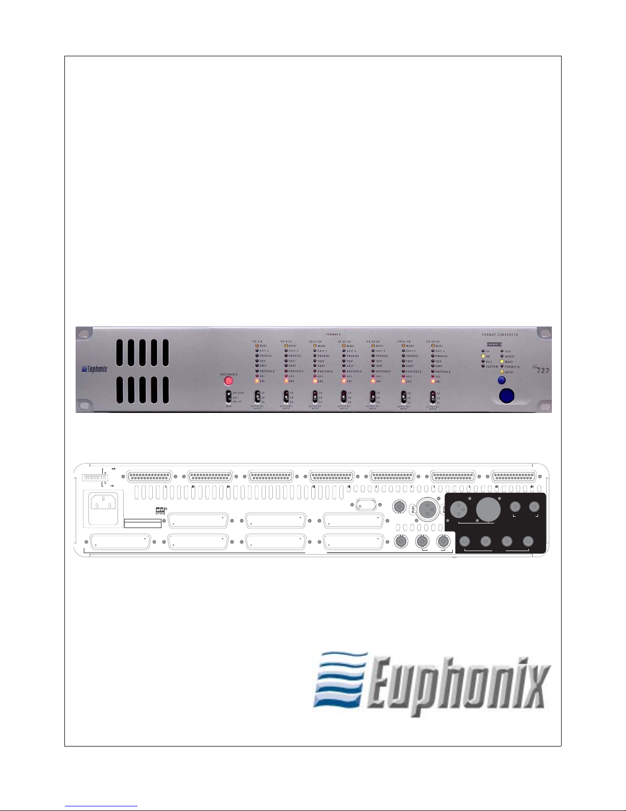
Euphonix FC727 Format Converter Operation Manual
v
Table of Contents
List of Figures ...................................................................................................................... vii
List of Tables ....................................................................................................................... viii
Chapter 1: Introduction and Interface..................................................................9
1.1 Basic Concepts........................................................................................10
1.1.1 Channels and Banks....................................................................10
1.1.2 Signal Flow .................................................................................10
1.1.3 Format A Inputs ..........................................................................11
1.1.4 Sample Rate Conversion.............................................................11
1.2 Front Panel..............................................................................................12
1.3 Rear Panel ...............................................................................................15
Chapter 2: Operating Instructions .......................................................................21
2.1 Pro Tools.................................................................................................21
2.2 SDIF-2 ....................................................................................................22
2.3 TDIF........................................................................................................22
2.4 ADAT .....................................................................................................23
2.5 ProDigi....................................................................................................23
2.6 AES.........................................................................................................24
2.7 Converting Between Third-Party Formats..............................................24
2.7.1 Using Two Units (56 Bidirectional Channels) ...........................24
2.7.2 Using One Unit (24 Bidirectional Channels)..............................25
2.8 Specifications..........................................................................................26
Appendix A: Pinout and Cable Specifications ..................................................27
A.1 AES/EBU DB-25....................................................................................27
A.2 Third-Party Devices................................................................................29
A.2.1 TDIF............................................................................................30
A.2.2 Pro Tools.....................................................................................32
A.2.3 SDIF............................................................................................34
A.2.4 ProDigi........................................................................................38


Euphonix FC727 Format Converter Users Manual
vii
List of Figures
1-1 FC727/726 front panel .......................................................................................................12
1-2 FC727/726 front panel (left) ..............................................................................................12
1-3 FC727/726 front panel (right)............................................................................................14
1-4 FC727/726 rear panel.........................................................................................................15
1-5 FC727/726 rear panel (left)................................................................................................15
1-6 FC727/726 rear panel (right) .............................................................................................18
A-1 AES DB-25 breakout cable assembly diagram..................................................................27
A-2 DB-50-to-DB-25 TDIF cable assembly diagram...............................................................30
A-3 DB-50-to-Hi-Dens 50 Pro Tools cable assembly diagram ................................................32
A-4 DB-50 MX3-to-DB-50 Male/Female SDIF cable assembly diagram ...............................34
A-5 DB-50 Male/Male-to-DB-50 Male/Female ProDigi cable assembly diagram ..................38

Euphonix FC727 Format Converter Users Manual
viii
List of Tables
1-1 Digital audio formats supported by the FC727/726.......................................................... 9
A-1 AES/EBU DB-25 connector pinout................................................................................ 28
A-2 Common DB-50 connector pinout and usage with third party devices.......................... 29
A-3 FC727/726 TDIF cable wiring specification .................................................................. 31
A-4 FC727 Pro Tools cable wiring specification................................................................... 33
A-5 FC727/726 SDIF cable wiring specification .................................................................. 35
A-5 FC727/726 SDIF cable wiring specification continued.................................................. 36
A-5 FC727/726 SDIF cable wiring specification continued.................................................. 37
A-6 FC727/726 ProDigi cable wiring specification .............................................................. 39
A-6 FC727/726 ProDigi cable wiring specification continued.............................................. 40

Euphonix FC727 Format Converter Users Manual
9
Chapter 1: Introduction and Interface
The Euphonix FC727/726 is a compact, 2U, digital-audio format converter that trans-
lates back and forth between MADI (Multichannel Audio Digital Interface) and the
digital audio formats listed in Table 1-1. AES/EBU outputs are always available, re-
gardless of the formats being translated. The FC727/726 performs the highest quality
sample-rate conversion (SRC) on all channels that require it.
The FC727/726 sets a new standard for format conversion devices with the following fea-
tures:
• Can apply different format conversion and/or SRC to each bank of eight channels.
• Automatically applies SRC when necessary but can be manually disabled.
• Performs format conversion and SRC on more channels (56) than other devices.
• Each of the 56 channels is bidirectional.
• Supports 24-bit audio at a 96 kHz sample rate.
• Maintains compatibility with older devices by offering 16- or 20-bit dithering and
supporting 96 kHz legacy standards.
Table 1-1 Digital audio formats supported by the FC727/726
Company/
Organization Format Name Equipment Using Format Transmission
Medium
Audio Engineers
Society
MADI Euphonix R-1, S-5, Sony 3348, many
large format digital consoles BNC cable
AES/EBU (AES-3)
Sony PCM-800, most DAT machines
and stereo D/A devices, sound cards,
effects processors
Two balanced XLR
cables
Tascam TDIF-1 (Teac Digital
Interface Format)
Tascam DA-88, DA-98, small format
digital consoles and workstations 25-pin cable
Mitsubishi ProDigi Otari and Mitsubishi digital multitracks Two 50-pin cables
Sony SDIF-2 Sony 3324 and 3348 Two 50-pin cables
Alesis ADAT Optical Alesis ADAT (type I and II), many small
format digital consoles and workstations
Two fiber optic
cables
Digidesign
(FC727 Only) Pro Tools Pro Tools systems 50-pin cable

Euphonix FC727 Format Converter Users Manual Introduction and Interface
10
The utility and power of the FC727/726 is exhibited by transferring digital audio be-
tween incompatible devices:
• Mixdown on a Euphonix System 5 digital console at 24-bit 96 kHz with source
material from a ProDigi or Sony tape machine at 48 kHz (automatic SRC).
• Mixdown on a Euphonix System 5 digital console from a ProTools workstation.
• Transfer tracks from a Tascam DA-88, Sony 3348, or Alesis ADAT to a Euphonix R-1.
The audio remains entirely in the digital domain so it suffers no degradation due to D/A
and A/D conversion.
1.1 Basic Concepts
1.1.1 Channels and Banks
The FC727/726 can convert 56 digital audio channels in two directions simultaneously
(simultaneous bidirectional conversion) with any of the supported devices. The 56 chan-
nels are divided into seven banks, each with eight channels. Each bank may be connect-
ed to a different third-party device running at a different sample rate (i.e., Tascam DA-
88 on channels 1–8, ADAT on 9–16, and Pro Tools on 40–48).
1.1.2 Signal Flow
Since 56 channels can be converted bidirectionally, signal routing can become confusing.
These simple rules should help clarify the signal flow:
• Audio arriving at the MADI B Input is sent out the Format A Output.
• Audio arriving at the Format A connectors is sent out the MADI B Output.
• The AES outputs always mirror the Format A Output.

Euphonix FC727 Format Converter Users Manual Introduction and Interface
11
1.1.3 Format A Inputs
Three connectors can be used by third-party inputs: the common DB-50 connectors, the
MADI A Inputs, and the DB-25 AES connectors. The appropriate signal is chosen
according to the following rules:
• If the MADI switch is ON, the MADI input is used for all 56 channels.
• If the MADI switch is OFF, either the common DB-50 or AES signals are used in
eight-channel banks.
If only one connector is in use, that format is selected.
If both are connected, the common DB-50 signal takes precedence.
Format A Adapters
To create a compact 2U device with maximum flexibility, the FC727/726 uses a com-
mon DB-50 connector for all third-party formats. An adapter is required to convert from
the DB-50 connector to the company’s own connector. The adapter is not intended to
be the connecting cable; it simply adapts the common DB-50 connector so it behaves
like the rear panel of the third-party device. These adapters are available separately
from Euphonix. In most cases, another cable is required to connect the adapter to the
third-party device. For example, a cable is required to connect the FC727 to a Pro Tools
computer just as it would be to connect to an 888-24 I/O unit. See Appendix A: Pinout
and Cable Specifications for detailed information.
1.1.4 Sample Rate Conversion
Digital audio devices have previously been required to use the same sample rate to op-
erate correctly together. The FC727/726 removes this limitation by allowing many
sample rates simultaneously. For example, by using the common DB-50 connectors,
each eight-channel bank can operate at its own sample rate. Furthermore, the FC727/
726 detects different sample rates and automatically activates SRC.
Although the FC727/726’s SRC is the highest quality available, some users may
still require an unaltered, bit-for-bit copy of the data. In this case, connected devic-
es can be slaved to the same sample clock, which disables SRC automatically (you
can also disable SRC manually).

Euphonix FC727 Format Converter Users Manual Introduction and Interface
12
1.2 Front Panel
The FC727/726’s front panel is shown in Figure 1-1. Enlarged sections of the front pan-
el are shown in Figure 1-2 and Figure 1-3; the numbers in the figures correspond to the
numbered items below describing that feature.
Figure 1-1 FC727/726 front panel
Figure 1-2 FC727/726 front panel (left)
❶
❸
❷
❹
❸❸❸❸
❹❹❹❹

Euphonix FC727 Format Converter Users Manual Introduction and Interface
13
1. MADI Switch
This three-position switch selects whether MADI is used for the Format A Input
and the characteristics of the MADI signal.
ON-STD: Selects the standard MADI settings used by Euphonix (sample rate =
frame rate).
OFF: Selects the common DB-50 connectors and ignores the Format A MADI
inputs. Use this setting with SDIF, TDIF, ProDigi, Pro Tools, ADAT, or AES devices.
ON-ALT: Selects MADI running at sample rate = 96 kHz, frame rate = 48 kHz.
2. SRC ENABLE Button
This button lights when the FC727/726 detects different sample rates on the A and
B formats and SRC is being used. Press the button when lit to turn off SRC. The
button flashes if SRC is needed but has been disabled by the user. Press the button
again to reset the FC727/726’s automatic SRC detection circuitry.
When a device first locks to the FC727/726, the button may occasionally light to in-
dicate SRC is necessary when it is not. Press the button twice to reset the FC727/
726’s automatic SRC detection circuitry. SRC is not needed if the button does not
light.
3. FORMAT A Input Indicator LEDs
Each eight-channel bank has seven LEDs to indicate the format attached to the
Format A Input; only one of these LEDs can be lit at a time. The LED lights dimly
yellow if an adapter is attached but the FC727/726 has not locked; the LED lights
bright yellow when the FC727/726 locks to the device.
The bottom SRC LED functions independently of the first seven. It lights red if
the FC727/726 has detected that SRC is required on that bank; it flashes red if
SRC is required but has been disabled by the user.
4. OUTPUT BIT DEPTH Select Switch
For each eight-channel bank, this switch sets the bit depth for the signal output to
the Format A device. When set to 24, all 24 bits are transferred from the MADI
input to the Format A output device without dithering. When set to 20 or 16, the
signal is dithered to the selected number of bits before being output to the Format
A device.
NOTE: This switch affects the Format A output only; it has no effect on the Format B
MADI audio output.

Euphonix FC727 Format Converter Users Manual Introduction and Interface
14
Figure 1-3 FC727/726 front panel (right)
5. FORMAT B Sample Rate LEDs
These LEDs indicate the Format B sample rate. If the rate is not 44.1, 48, or 96 kHz
(±3%), the CUSTOM LED lights. Since the FC727/726 supports SRC, Format A
may operate at several sample rates that are not indicated by individual LEDs.
6. FORMAT B Sync Source LEDs
These LEDs shows Format B’s sync source. The blue button below the AUTO
LED manually toggles the sync source sequentially from AUTO to AES,
WORD, MADI, and FORMAT A. When set to AUTO, the FC727/726 accepts
the first sync signal detected with the following priority: AES, WORD, MADI,
and FORMAT A. For example, if MADI and Format A sync are both present,
the selected source will be MADI because it is higher in the priority list.
7. Power Switch
This switch turns power to the FC727/726 on or off.
❺❻
❼

Euphonix FC727 Format Converter Users Manual Introduction and Interface
15
1.3 Rear Panel
The FC727/726’s rear panel is shown in Figure 1-4. Enlarged sections of the rear pan-
el are shown in Figure 1-5 and Figure 1-6; the numbers in the figures correspond to the
numbered items below describing that feature.
Figure 1-4 FC727/726 rear panel
Figure 1-5 FC727/726 rear panel (left)
1. AC Power Input
Connect the power cable shipped with the FC727/726 to its AC input and an AC
mains power source.
2. Format A Common DB-50 Connectors
Seven common DB-50 connectors connect third-party devices to the FC727/
726. Each connector provides eight bidirectional audio channels. You must use
the appropriate adapters for each format to connect the third-party devices. See
Format A Adapters on page 11.
FC727
EUPHONIX, INC.
PALO ALTO
MADE IN THE U.S.A.
AES 49-56 AES 41-48 AES 33-40 AES 25-32 AES 17-24 AES 9-16 AES 1-8
SERVICE
IN
IN
AES
SYNC AES SYNC
WORD SYNC
IN OUT
FORMAT B
MADI A MADI B
IN 2 OUT 2
IN 1 OUT 1
IN
CH 49-56 CH 41-48 CH 33-40 CH 25-32
CH 17-24 CH 9-16 CH 1-8
SDIF-2 SYNC
or
SLAVE CLK
OUT
FORMAT A
OUT
VA C FUSE
100-240 1.0-0.5A 2.5A
50/60Hz SLOW
CURRENT
FMT A FMT B
AES STEREO
AES MONO
FMT A AES/FMT B/FMT A
IN THRU
SLAVE CLK
CAUTION: To prevent risk of fire
replace fuse with the same type and rating,
FC727
EUPHONIX, INC.
PALO ALTO
MADE IN THE U.S.A.
AES 49-56 AES 41-48 AES 33-40 AES 25-32 AES 17-24 AES
9
SERVICE
IN
IN
AES
SYNC
MADI A
IN
CH 49-56 CH 41-48 CH 33-40 CH 25-32
CH 17-24 CH 9-16 CH 1-8
SDIF-2 SYNC
or
SLAVE CLK
OUT
FORMAT A
OUT
VA C FUSE
100-240 1.0-0.5A 2.5A
50/60Hz SLOW
CURRENT
FMT A FMT B
AES STEREO
AES MONO
FMT A AES/FMT B/FMT A
SLAVE CLK
❶
❸
❷❹
❺
❻
❼
❷❷
❷❷
❷❷
❸❸❸❸❸
➑
➒

Euphonix FC727 Format Converter Users Manual Introduction and Interface
16
3. Format A AES Connectors
Seven DB-25 connectors connect AES devices to the FC727/726. Each connector
provides eight bidirectional channels (four AES pairs). To connect to the third-party
devices, use the DB-25-to-XLR breakout cable available from Euphonix.
NOTE: Do not use DB-25-to-XLR breakout cables made by other companies because
the pin numbering may be incompatible! See Appendix A: Pinout and Cable
Specifications for specific cable information.
4. Format A MADI IN and MADI OUT
The Format A MADI In and MADI Out BNC connectors interface with non-Eu-
phonix MADI devices. At 48 kHz, MADI A provides 24-bit audio on 56 chan-
nels. At 96 kHz, only 28 24-bit audio channels (1–28) are available.
NOTE: Unlike MADI B, which has a second set of I/O connectors, MADI A provides
only 28 channels at 96 kHz.
5. Service DB-9 Jack
This jack connects to a PC’s serial port to upgrade the FC727/726 firmware.
CAUTION: Do not connect anything to the Service DB-9 jack unless instructed to do
so by Euphonix technical support.
6. DIP Switches
These eight DIP switches (numbered 1–8 from left to right) set various modes on
the FC727/726. Switches 3–5 and 7 are not currently implemented.
Switch #1 Bidirectional mode
Flip this switch when converting between third-party formats using one FC727/
726 (see page 25).
Switch #2 MADI MERGE
When set to MADI MERGE (down), Format B MADI Input 1 channels 1–24 are
merged with Format B MADI Input 2 channels 1–28 and Format B MADI Input
1 channels 25–28 to form a single 56-channel input stream. Format B MADI Out-
put 1 sends channels 1–56 and Format B MADI Output 2 sends channels 25–56
followed by 1–24 from the third-party inputs.

Euphonix FC727 Format Converter Users Manual Introduction and Interface
17
Switch #6 AES MASTER/SLAVE
When set to SLAVE (up), the Format A AES outputs lock to their corresponding
AES inputs. Within each bank, all AES outputs operate at the sample rate of the
lowest-numbered, locked AES input. For example, if the first bank (channels 1–
8) has a 44.1 kHz AES signal connected to inputs 1/2 and a 48 kHz input connect-
ed to inputs 5/6, then AES output channels 1–8 will all run at 44.1 kHz. If AES
inputs are not present on a bank, Format A will get sample clock from the Format
B Sync input. If sync is not present, Format A will then lock to the Format B Sync
Input.
When set to MASTER (down), Format A’s AES outputs get sample clock from
the Format A Sync input. If Format A sync is not present, Format A’s AES outputs
will then lock to the Format B Sync Input.
Switch #8 AES STEREO/AES MONO
Set this switch to AES Stereo (up) for the normal configuration where each AES
signal contains two discreet channels. If the sample rate is above 52 kHz (i.e., 96
or 88.2 kHz), and the AES signal connected to the FC727/726 implements two-
wire AES (also referred to as mono mode AES), set the switch to AES Mono
(down). This setting treats each AES signal as a single channel with a frame rate
running at half its sample rate. For example, a 96 kHz two-wire AES signal runs
at 48 kHz by using the left channel for the even samples and the right channel for
the odd samples. This switch affects both the AES inputs and outputs.
7. Format A AES Sync In
Connect an AES sync signal to this XLR connector to synchronize the Format A
MADI signal. According to the AES specification, the AES sync signal must use
the same sample rate as the incoming MADI signal to operate correctly.
NOTE: It is possible, but not recommended, to connect a MADI signal without using
a corresponding sync signal. Providing an AES or Word sync results in lower
jitter and should be used whenever possible.
8. SDIF-2 or SLAVE CLK IN
This connector can receive either an SDIF or slave clock sync signal. The FC727/
726 automatically detects which signal type has been connected.
An SDIF device must send a word sync signal to this connector to properly con-
nect to the FC727/726.

Euphonix FC727 Format Converter Users Manual Introduction and Interface
18
A slave clock is a sync signal that runs at 256 times the sample rate. This is most
commonly implemented in Pro Tools systems and is also referred to as a super-
clock. Pro Tools users may optionally connect the slave clock output from another
Digidesign Audio Interface or Synchronization unit (i.e., 888-24) to the Slave Clk
In connector to synchronize both devices.
9. SLAVE CLK OUT
Pro Tools users may optionally connect the Slave Clk Out to another Digidesign
Audio Interface or Synchronization unit (i.e., 888-24) to synchronize both devices.
This allows both a Digidesign I/O unit and the FC727 to be connected to the same
Pro Tools computer.
If Slave Clk In has a valid sync signal, it is passed through to Slave Clk Out. If
Slave Clk In does not have a valid sync signal, the lowest numbered bank that is
locked and in use is selected as the clock source.
Figure 1-6 FC727/726 rear panel (right)
10. Format B MADI IN 1 and MADI OUT 1
These BNC connectors are used to interface with a MADI device. (Euphonix users
can connect these to a Studio Hub, MA703, or AM713) At 48 kHz, the Format B
MADI In 1 and MADI Out1 connectors provide 56 24-bit audio channels. At
96 kHz, they provide 28 24-bit audio channels (channels 1–28).
AES 9-16 AES 1-8
IN
AES
SYNC AES SYNC
WORD SYNC
IN OUT
FORMAT B
MADI A MADI B
IN 2 OUT 2
IN 1 OUT 1
IN OUT
IN THRU
10 11
12 13 14 15

Euphonix FC727 Format Converter Users Manual Introduction and Interface
19
11. Format B MADI IN 2 and MADI OUT 2
At 96 kHz, the Format B MADI In 2and Out 2 connectors provide 28 additional
24-bit audio channels (29–56).
At 48 kHz, Format B MADI In 2 is ignored and Format B MADI Out 2 carries
the same audio as Format B MADI Out 1 but with the channel numbering re-
versed: Format A channels 29–56 are output on Format B MADI Out 2 chan-
nels 1–28; Format A channels 1–28 are output on Format B MADI Out 2
channels 29–56.
12. Format B AES SYNC IN
Connect an AES sync signal to this XLR connector to synchronize the Format B
MADI signal. According to the AES specification, the AES sync signal must use
the same sample rate as the incoming MADI signal to operate correctly.
NOTE: It is possible, but not recommended, to connect a MADI signal without using
a corresponding sync signal. Providing an AES or Word sync results in lower
jitter and should be used whenever possible.
13. Format B AES SYNC THRU
This connector outputs a copy of the Format B AES Sync In signal.
14. Format B WORD SYNC IN
Connect a word sync signal to this BNC connector to synchronize the Format B
MADI signal. According to the AES specification, the word sync signal must use
the same sample rate as the incoming MADI signal to operate correctly.
NOTE: It is possible, but not recommended, to connect a MADI signal without using
a corresponding sync signal. Providing an AES or Word sync results in lower
jitter and should be used whenever possible.
15. Format B WORD SYNC OUT
This connector outputs a copy of the Format B Word Sync In signal. However,
this output generates a word sync signal at the Format B sample rate even if noth-
ing is connected to Format B Word Sync In. Note this important difference in
behavior from Format B AES Sync Thru.

This manual suits for next models
1
Table of contents
Other Euphonix Media Converter manuals
Popular Media Converter manuals by other brands

THOR
THOR HD-IRD-V3 user manual

B&B Electronics
B&B Electronics ELinx EIR-G-SFP-T quick start guide

Teradek
Teradek Slice quick start guide

Bosch
Bosch Rexroth EFC 3600 instruction manual

Keyautomation
Keyautomation 900EGKD2 Instructions and warnings for installation and use

Vivo Link
Vivo Link VLHDMISP1X4 user manual

Skytech
Skytech SkyBridge 7060TX Installation and operating instructions

Thor Broadcast
Thor Broadcast H-12HDMI-QAM-IPLL user manual

Tolomatic
Tolomatic ServoChoke SVC07 user guide

Lavry
Lavry AD122-96 Mark III Operation manual

Extron electronics
Extron electronics IN1403 user manual

Lindy
Lindy 42926 user manual