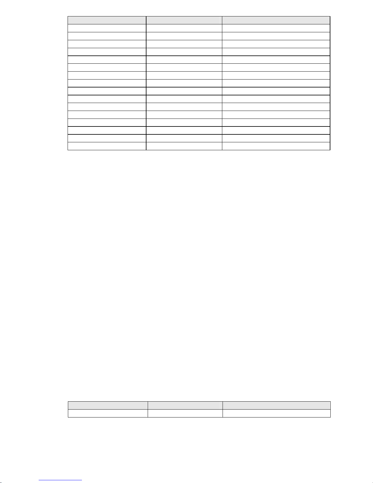
Level GB 200 User manual

Set GB 200 with Built-in GSMModule
Two-way Converter of Phone Line on GSM
USER GUIDE
LEVEL
GSM GATE PROFESSIONAL

1
Dear customers,
wewould like to congratulate you on buying our product – GSM Gate GB 200. Thisway you obtained
high-class andtechnically highly modern product.
GSM Gate by LEVEL allowssignificant phone costs savings as well as installation of phone line even
in place where it otherwise wouldnot be possible. At the sametimeGB200 allowsuse of highly
modern way of communication by SMS messages, which can be advantageously used for first-class
protectionof properties, remote control of household appliances, etc.
In additionit offers number of parameters, which canbe programmed inorder to achieve easy
handling during operation.
Before connection of GB 200 and its setting into operation, please, read carefully this instructions
manual.It will not only introduce you correct installation and handling of this product but at the same
timewill help you fully utiliseallits technical potentialities.
Allowed use
GSM Gate GB200 171 allowsconnection of extension exchange input (free position for direct line) or
phone device tophone line connector.
ATTENTION: GB 200 171 is source of phone line therefore never connect either direct or extension
phone lines to connector. GSM Gate 200 271 is, on the contrary, end deviceof phone line and is
intended for extension lines of phone exchanges. GB 200 271 can be used only on extension
exchanges, where engaged or dial tone certainly occurs after hang-up of phone of opposite extension
line or exchange disconnects line voltage for ashort time.
ATTENTION: GSM Gates are not subject of homologation by TÚ (Czech Telecommunication Office).
Entrepreneur is therefore obliged to ensure that callsfrompublicnetwork JTS are not connected
through them (only internal – extension – calls are allowed).
Power supply of the product canbe carried out by network adapter delivered with product or by
backup source 12 Vss. Product can be used only in closed rooms, not outside.It isnecessary to
avoid all contacts of device with moisture. Another than above stateduse can cause incorrect function
or damage ofproduct. This iscombinedwith danger – e.g. short circuit, fire or injury by electric
current.

2
TABLE OF CONTENTS - GSM Gate GB 200
1. Description and Usage of Product. 3
1.1. Content of Delivery. 3
1.2. Equipment, which can bebought additionally. 3
2. Safety Instructions. 3
3. Installation. 3
3.1. GSM GateAssembly. 3
3.2. Connection of Cables and Aerial. 4
3.3. Insertionof SIM cards. 4
3.4. Indication by LED. 4
4. Programming. 5
4.1. Programming fromPC. 5
4.2. Programming through Phone Line. 5
4.3. Programming by SMS Messages. 5
5. Control Instructions. 6
5.1. PIN in GB 200. 6
5.2. Set-up of Direction Adding. 7
5.3. Set-up of Allowed Directions. 7
5.4. Code for Disallowed Directions. 8
5.5. Set-up of Fixed Pre-set toExtension. 9
5.6. Ringing after Connection. 9
5.7. Set-up of Delay before Dial. 9
5.8. Set-up of Waiting Time for Dial. 10
5.9. Set-up of Number Control. 10
5.10. Set-up of Number of Figures after which Number Is Dispatched. 10
5.11. Set-up of DialTone Type. 10
5.12. Set-up of Programming Symbol #/ *. 10
5.13. Set-up of Tariffs. 11
5.14. Termination of Callwhen Line Is Silent. 11
5.15. Time for Pre-set. 11
5.16. Transmission of SMS Messages into PC. 11
5.17. Switch-on of SIM Card. 12
5.18. Set-up of Base SIM Card. 12
5.19. Blocking of SIM Card by PIN. 12
5.20. Assignment of SIM Cards to Allowed Pre-selections. 12
5.21. Number for Information SMS Messages. 13
5.22. Set-up of Number for Monthly Upkeep Calling. 13
5.23. ALARM Inputs and Set-up of A-numbers for SMS Despatch. 14
5.24. Set-up of B-numbers for ALARM SMS Messages. 14
5.25. Set-up of Numbers forALARM Calling. 15
5.26. Set-up of Text of ALARM SMS Messages. 15
5.27. Set-up of Logical Level of Outputs. 15
5.28. Statement of AllSet-up Parameters. 15
5.29. RESET of Gate. 16
5.30. Initialisation of Gate toInitialSet-up. 16
6. Operation. 16
6.1. Outline of Tones. 16
6.2. Operation during Current Outage. 16
7. List of Programming Instructions. 17
8. Subsidiary Programs for PC. 19
8.1. Installation. 19
8.2. GB200cfg - Programfor Configuration of GB 200 from PC. 19
8.3. GBserver - ProgramforDistribution of SMS Messages. 19
8.4. GBsms - Programfor Reception and Dispatch of SMS Messages. 19
9. Basic TechnicalParameters. 20
10. Guarantee Certificate. 21
11. Guarantee Conditions. 22

3
1. DescriptionandUsage ofProduct.
GSM Gate GB 200 is two-way converter of classic phone line for calls to cell phone GSM network.
At the same time device allowsdispatch of prepared SMS messages on the basis of changes in
voltage on inputs andevaluation of incomingSMS messages for set-up of outputs.
1.1. Content of Delivery.
1 x GSM GateGB 200.
1 x Network adapter 12 V ss.
1 xSerial cable for PC 2m.
1 x Floppy disc with programs GB200cfg, GBserver and GBsms.
1 x Phone cablefor trial connection of phone or exchange.
1 x External aerial mast with cable 3m.
1 x Fixation set – fasteners, screws and drilling template.
1 x Instructions manual.
1.2. Equipment, which canbe bought additionally
Connector CANNON15 with cover.
Connector CANNON15 with built-in micro-relay for separation of circuits.
2. SafetyInstructions.
GSM Gates by LEVEL are conformable with technical standards foroperation in our mains. Power
source with voltage 10.6 – 16 V ss fitted with connector with positivecentralcontact shall be used
for power supply. Dimension for current 600mA – maximumpower take-off during call, securing –
safety-fuse T 1A.
Device must be disconnected from allpower sources before maintenance or exchange of parts or
filled boards.
No fluids must enter the device. Danger of fire or injury by electric current impend. Do not place
device intorooms with high temperatures, strong vibrations or high humidity.
In case you moved device fromcool to warmroomdo not set it into operation immediately. Let
device warmupto temperature of room. Wait until condensedwater evaporates.
3. Installation.
3.1. GSM Gate Assembly.
GSM Gates by LEVEL are designed for operation in dry places. During assembly avoid hot
places and placeswhere device would be exposed to direct solar radiation or placesclose
to heatingelements.
Do not place GSM Gate or aerial mast close to phone exchange or other electronic device
or line. Dueto high-frequency electromagnetic field thesedevices could be interfered.
Choose such aplace where interference is minimal. Due to interference it isalso not
advisable to operate the device close to other power or high-frequency devices. Before
assembly prove if there issufficient level of signal required by GSM network in selected
place.

4
When using for protection ofproperty, it isconvenient to arrange protection ofinstallation
area against break-in and destruction of function of GB 200.
3.2. Connectionof Cables andAerial.
Phone cablewith end US RJ shall be used forconnectionof phone line. Lengthof
connecting cable for installation should not be shorter than 5meters sothat it is possible to
place GSM Gate and aerial in sufficient distance fromexchange. However, phone cable
should not be longer than 200 m.
Connection cables for signals, which operate SMS messages, shall be connected to
connectorCANNON15 according to recommended connections – see chapter 5.22.
Serial cable CB 110 030, which isdelivered with product, or other serial „CROSS“ cable
with maximumlength of 10 meters shallbe used for connectionof PC.
External aerial, which is apart of equipment, shall be screwed into connector for aerial. In
casesignalis weak use moresensitive aerial.
Network adapter shall be connected at first with GSM Gate - into connector marked 12VDC
-and then plugged into socket. Supply frombackup battery can beconnected toconnector
marked 12V BAT.Thissupply will be automatically switched on if voltage of main supply
drops under level of voltage of backup source.
3.3. Insertionof SIM Cards.
Each SIM card includes PIN set by producer. It isfour-figure-number which is required by
SIM card at start-up of communication with GSM module if blockingof SIM card by PIN is
active.
SIM card shall be insertedunder sliding lid on left downcorner of GB200. Gently press the
lid inside and down at its upper end.
If callis just not carried out supplyof contacts in SIM card connectors is disconnected by
removal of the lid and manipulation with SIM card is possible without danger of damage.
When inserting SIM card place contact field facing downand notch in the direction of
symbol, which is drawn in bezel. After insertion of SIM card push in the lid. Don’t manipulate
with SIM cards while calling!
If you insert only one card it does not matter, in which bezel you insert it. It isonly
substantialtoset-up correct position in consecutive configuration.
So as GSM gate co-operates with SIM cardsit is necessary toensure that PIN SIM1 and
PIN SIM2 set in configuration of GB 200 really correspond to PINsof inserted SIM cards or
blocking of SIM cards by PINmust not beactive.
3.4. IndicationbyLED
Indication LEDs on GB 200 indicate basic operationalstates:
PWR
permanentlyalight - signalises connectedpower supply
flashing - hardware initialisationin process
GSM1and GSM2
permanentlyalight - signalises loginin GSM network
flashing - login in network in process
simultaneous flashing- removed lid

5
STATUS
copies stateof phone line
permanentlyalight - line pickedup
quick flashing - dial of number
slowflashing - ringing
2 flashes - programming regime
4. Programming.
Number of functions and parameters, which allowmaximumadjustmentof gate GB200 to
environment and user’srequirements, can be set by programming.At the sametime itis possible
to set values of 8 output signals byprogramming.
Set-up ofall parameters canbe carried out in threeequivalent ways.
Through serial line from PC.
Remote fromcellphone or Internet by SMS messages.
Through phone line from classic phone.
4.1. Programming from PC
1) Install programGB200cfg for WIN95, 98 fromfloppy disc, which is part of delivery,
in your PC.
2) Connect GB 200to serialport of PC by delivered cable andrun program GB200cfg.
3) You can read actual configurationfromGB200, edit all parameters and save
configurations ondisc.
4) Configuration becomes valid immediately after dispatching into GB 200. If change
of PIN was part ofconfiguration prove login of GB200 in network byswitching-off
and on.
4.2. Programming throughPhone Line.
It is carried out by dialling of numbers on phone line by phone with frequency dialling.
1) Pick up receiver. If you have GB 200 271, dial extension number, onwhich gate is
installed. You will hear dialling tone of GSM gate.
2) Dial #pppp#, where pppp are four figures of PIN for SIM1. PIN 0000 is set from
production for SIM1. After enteringcorrect PINyou will hear tone “programming”.
3) Enter particular setting parameters. Dial 4figures ofinstruction followed by value
of parameter for particular instruction.
4) End entering of instruction by dialling #. Time control is 1minute after last dial.
After entering correct instructionyou will hear tone “programming” again and
another instruction can be entered.
5) Programming regime will be exited by hang-up of receiver.
If you enter incorrect programming code you will hear engaged tone. In this case dial#
again and carry on programmingor exit programming regimeby hang-up of receiver. If
correct programming codeswere already entered set-up, which was programmed by them,
will be saved. If *issetas programming symbol instead of #use *in all programming
instructions.
4.3. Programming and OperatingbySMS Messages.
SMS messages coming to phone number of SIM card, which is active in GB 200 are
decoded. Control messagesare immediately realised, othersare dispatched through serial
line to PC – if this issetin configuration. If you send control message to phone number of
SIM card, which is not active, this message will be realised after activation of card fromGB
200 – at switch-over to the other SIM card – if validity of SMS message in network does not
expire sooner.

6
General format of control SMS messageis following:
XXppppINSTRUCTION1 parameter1 INSTRUCTION2 parameter2 Instruction3…
XX Opening figures – two capitalletters X.
pppp Actual PINof gate for SIM1.
INSTRUCTION Key word of instruction inSMS message – capitalor smallletters do
not matter. Space or = follows.
Parameter1 Set-up value of instructionNo.1.
End of instruction sequenceshall be carried out either byending of
SMS message or space.
Space or enter in SMS messagecan be followed by other key words of instructions and
their parameters up to maximum length of SMS message, tm. up to 160characters.
Programming can be carried out by dispatch ofSMS message from another cell phone,
eventually fromInternet by themeans of services on wwwpages of operators.
Message about fulfilment of instruction isalways sent back to sender’s cellphone. No reply
is dispatched to instructions sent from Internet.
If parameter INFOSMS issetmessagesabout changes in set-up, messages about reset
and information about time of operation are sent to this number.
Deleting of numeral or text data is carried out by substitutionof parameter value by point .or
quotes “”.
5. Control Instructions.
All parametersof GB 200 can be set fromPC through serial line, by phone in programming
regimeor by texts of instructions in SMS messages, whichfollowafter XXpppp.
5.1. PIN in GSM Gate GB 200.
So as GSM Gate co-operates with SIM cardsit is necessary to ensure that PIN SIM1 and
PIN SIM2 setin configuration of GB 200 really correspond to PINs of inserted SIM cards. It
is eventually possible deactivate blocking of SIM cards by PIN but this meansthat blocking
must be also switchedoff in configuration of GB 200.
At the same timePIN SIM1 is usedas access code for programmingby SMS messages or
by phone. PIN SIM1= pppp.
Instruction by Phone SMS Instruction Pre-set
0001nnnn# PIN1 nnnn 0000 Change of PIN SIM1
0002nnnn# PIN2 nnnn 0000 Change of PIN SIM2
Where nnnn are four figures of newPINs
Example:
Original PIN ofGSM gate is0000. PIN of SIM card,which will be used in GSM gate on
position2, is 1234.
●Pick up receiver and wait for dialling tone.
●Enter programming regimeby dialling #0000#.
●Afterhearing of programming tonedial 00021234#.
●Hang up and wait for approx. 20 seconds – green LEDon phone starts to flash.

7
If you donot knowPINof GSM gate carry out hardware initialisation – see chapter 4.17.
It is not possible to program gate by SMS messages if PIN SIM in gate is not conformable to
PIN of SIM card. Login ofgate inGSM network isthen not carried out. This is e.g. state
after initialisation. For conformity of PINs choose another way of programming.
GSM gate confirmsreception of instruction by sending of SMS message, which includes
newset value of PIN, back to sender.
In case you forget current PINof GSM gate you can carry out reading of actual
configurationof gate inPCby means of program GB200cfgor hardware initialisation of
parametersto original set-up fromproduction.Thisshall be realised by interconnection of
outputs No. 9and 10 on connector CANNON 15 and simultaneousconnection of supply
adapter to network.
5.2. Set-up ofDirectionAdding.
Some exchanges do not repeat pre-selection of number dialled before interconnection when
connecting call to transmitterwith GSM gate. This function allows reconstruction of originally
dialled number by adding of removed pre-selection.
Instruction by Phone SMS Instruction Pre-set
0100n# PDIR n Not activated in production.
Where nis 0to 7figures, which shall be added
Removal of values by phone is carried out by instruction 0100# or by SMS message PDIR .
(point represents data)or PDIR ““
Example: Exchange removes pre-selection 0fromdiallednumber 0606-445566 and
transmits only number606-445566 down the line.
●Enter programming regimewith #pppp# (see paragraph 4.2.)
●Dial 01000#.
●Hang up.
From thismoment GSM gate puts pre-selection 0in frontof each phone number read on
phone line. Thismeans thatnumber 606-445566 will be reconstructed to number 0606-
445566.
5.3. Set-up ofAllowedDirections.
If you want to avoid connection of useless calls (which would have higher tariffs than when
connected through fixed line) through GSM gate set required values of pre-selectionsas
allowed directions. Other calls, e.g. callsinto fixed local or toll phone network, will not be
connectedthrough GSM gate.
n is 1 to 7-figure-number of pre-selection
Removal of values is carried out by instruction 0201#, 0202#, etc. or by SMS message
ADIR1 .(point represents data) or ADIR ““

8
Instruction by Phone SMS Instruction Pre-set
0201n# ADIR1 n 0601 Eurotel
0202n# ADIR2 n 0602 Eurotel
0203n# ADIR3 n 0603 Paegas
0204n# ADIR4 n 0604 Paegas
0205n# ADIR5 n 0605 Paegas
0206n# ADIR6 n 0606 Eurotel
0207n# ADIR7 n 0607 Eurotel
0208n# ADIR8 n 0608 Oskar
0209n# ADIR9 n 0723 Eurotel
0210n# ADIR10 n 4 Internet call
0211n# ADIR11 n 5 Internet call
0212n# ADIR12 n 0 Everything allowed
0213n# ADIR13 n Backup
0214n# ADIR14 n Backup
0215n# ADIR15 n Backup
0216n# ADIR16 n Backup
ATTENTION!
●If you remove allvalues GSM gate will not connect any callsexcept numbers, which
begin with code for unblocking, if it isset. After end of dialling ofnumber you will hear
engaged tone.
●If you also allowconnection of calls to fixed phone network change parameter “number
of figures” so that longer numbers can be connected, too.
●If you want to allowcalls to all directions – tm. to fixed phone network either – set
number “0” as oneof allowed numbers.
●If you use function of automatic switch-over to second SIM card according to dialled
number (parameter No. 19 – SIMDIR), set numbersof pre-selections fromlongest to
shortest. Priority of evaluation goes fromabove.
Example:
You want to disallowusage of gate for Paegas and fixed phone lines, and allowusage of
number with pre-selection 072 instead:
●Enter programming regimewith #pppp# (see paragraph 4.2.)
●Dial 0203#0204#0212#02140724# and hang up or send SMS message XXppppADIR3
. ADIR4. ADIR12 . ADIR14 072(see chapter 4.3.)
Fromthis moment numbers beginning with 0601, 0602, 072, 0606, 0607, 0608, 4 a 5 will be
allowed. Other calls will not beaccepted by gate.
5.4. Code for DisallowedDirections.
Code for disallowed directions, dialled in front of phone number,allowsdialling of numbers,
which are not in list ofallowed directions. When dialling number into gate, calling isallowed
by dialling of correct code in frontof phone number. Gate then removescode and sends
only phone number in GSM. We recommend to use in applications where gate is accessible
frompublic network afterpre-selection.
Where nis 0to 7figures, which shall be removed
Instruction by Phone SMS Instruction Pre-set
0300n#... CDIR n ... Not activated in production.

9
Removal of values iscarried out by instruction 0300# or by SMS message CDIR .(point
represents parameter)
Example: You want to enter code for unblocking of disallowed directions 1234.
●Enter programming regimeby dialling #pppp# (see chapter 4.2.)
●Dial 03001234# and hang up or send SMS message XXpppp CDIR 1234 (see chapter
4.3.)
Fromthis momentGSM gate connects also phone numbersbeginning with 1234 in addition
to allowed directions. This code will be removed and rest of dial will be sent intoGSM.
5.5. Set-up ofFixedPre-set to Extension.
Parameter is accessible only for gate GB 200 271. During incoming call pre-set by
frequency dialling fromcell phone is awaited for set time(see 5.14.). If pre-set is notcarried
out and line still has dialling tone gate carries out dialpulse ofpre-set number of extension
after expiry of set time. This means that ifno frequency pre-set isreceived fromcell phone
incomingcall is connected to set extension.
Where nis 0to7figures – numberof extension, to which incoming calls shall be connected
if no pre-set is received
Removal of values iscarried out by instruction 0400# or by SMS message IDIR .(point
represents parameter) or IDIR ““
5.6. Ringing after Connection.
Someexchanges require ringing after initial connection ofline onto input transmitter. This
function allowssetting of switch-on of control ringing for required time. Function isnot
accessible inGB 200 271.
Instruction by Phone SMS Instruction Pre-set
0500xx#... IRING xx ... 8, tm. 0.8s set from production
Where xx isnumber in range from00 to 20 and means time in tenths ofseconds, tm. 0.0 –
2.0s
5.7. Set-up ofDelaybefore Dial.
After occupation of transmitter someexchanges cause glimmer of line, which could be
evaluated as number by GSM gate. Thisfunction allowssetting of delay after moment of
pick-up. During this delay situationon line will beignored. Function only for GB 200 171.
Instruction by Phone SMS Instruction Pre-set
0600xx#... DELAY xx ... 3, tm. 0.3s set from production
Where xx isnumber in range from00 to 99 and meanstime in tenths ofseconds, tm. 0.0 –
9.9 s
Instruction by Phone SMS Instruction Pre-set
0400n#... IDIR n ... Not activated in production

10
5.8. Set-up ofWaiting Time forDial.
After picking up GSM gate gives you dialling tone, which notifies you about possibility of
dialling of number. After settimedialling tone changes to engagedtone and reading of
dialled phone number is terminated.
Instruction by Phone SMS Instruction Pre-set
0700ss#... TLINE ss ... 60, tm. 60s set fromproduction
Where ss is number inrange from 10 to120 and means time inseconds, tm. 10 - 120s
5.9. Set-up ofNumber Control.
After dialling of last figure of number GSM gate waits for set time incase further number
is dialled. After expiry of this timereading of dialis terminatedand dial is sent to GSM.
Instruction by Phone SMS Instruction Pre-set
0800ss#... TDIALss ... 4, tm. 4s set fromproduction
Where ss is number in range from01 to 20 and means timein tenths of seconds, tm.1-
20s
5.10. Set-up ofNumber ofFigures after which NumberIs Dispatched.
If set allowed directionsofGSM gate are only cellphone numbers, which always have
maximumnumber of 10 figures, it is sensible to set 10 as maximumnumber of figures. After
setting of 10th figure dialling of number starts immediately without necessity of waiting for
control.
Instruction by Phone SMS Instruction Pre-set
0900nn#... LDIAL nn ... 10 set from production
Where nn is number in range from 03 to24 and means maximum numberof figures
5.11. Set-up ofDial Tone Type.
It ispossible to set up different type of dial tone of GSM gate for each SIM card in order to
control that call is made through correct connection route.
Instruction by Phone SMS Instruction Pre-set
1001t#... TONE1 t ... 2 set from production for SIM1
1002t#... TONE2 t ... 3 set from production for SIM2
Where tis number from0to4 andspecifies type of dialtone (see chapter 6.1.)
5.12. Set-up ofProgrammingSymbol # / *.
If symbol # is used by extension exchange for any service concurrent with functions of GSM
gate it is possibletoset that symbol * is used exclusively inall instructions insteadof symbol
#.
Instruction by Phone SMS Instruction Pre-set
1100z#... FLAG z ... 0, tm. # is set fromproduction
Where zis 0 or 1where 0 means usage of # and 1means usage of *

11
5.13. Set-up ofTariffs.
Parameter allowsoptimal setting of way of transmission of information about start-up and
length of GSM calltoextension exchange.
Instruction by Phone SMS Instruction Pre-set
1200k#... TARIFk ... 0, tm. no tariff set from production
Where kis 0 to 63
0 No transmission
1-60 Periodicalimpulse 16kHz in interval from 1 to 60s
61 Change of polarity when picked upby calledparty (forGB 200 171)
62 Flash impulse when picked up by called party(for GB 200 271)
63 16 kHz impulsewhen pickedup by called party
5.14. Terminationof Call whenLine IsSilent.
Parameter only for GB200 271. If exchange terminatesphone call between extensions for
any reason and engaged or dial tone isnotemitted and inaddition opposite GSM
participant does nothang up it canhappen that call inGSM stays uncollected. For this case
it ispossibleto activate monitoringof silence online. If silence on line is longer than one
minute, call shallbe disconnectedif this function is activated.
Instruction by Phone SMS Instruction Pre-set
1300z#... SPEECH z ... 1, tm. functionactivated, set from
production
5.15. Time for Pre-set.
During incoming call from GSM gate GB 200 271 picks up extension line and awaits pre-set
by frequency dialling fromcell phone for set time. If pre-set is not carried out set number of
extension is automatically dialledby pulse dial(seechapter 5.4.).
Instruction by Phone SMS Instruction Pre-set
1400ss#... WAITss ... 5, tm. 5s set fromproduction
Where ss is 1 to 25 s
Transit of frequency pre-set fromGSM into phone exchange is not reliable in somecases.
This problemcan be solved by reinforcementof sensitivity of frequency dial receiver of
particular extension line inexchange.
5.16. Transmission ofSMS MessagesintoPC.
If you want to use function of reception of SMS messages by connected PC through RS232
it is necessary to activate dispatch by this function.If function is active and SMS messages
are though not read fromGB200by PC it can mean that SMS memory in GB200 isfull.
Further SMS messagesare then not accepted and it might therefore happen, that control
instruction included in SMS message isnot carried out. If function is switched off all
eventual instructionsincluded in incoming SMS messagesare carried out and all SMS
messages are deleted.
Instruction by Phone SMS Instruction Pre-set
1500z#... HOSTSMS z ... 0, tm. function switched off, set
fromproduction
Where zis 0 or 1- 0 off, 1 on

12
5.17. Switch-onofSIMCard.
All function related to particular SIM card can be switched off by thisparameter regardless
of other set-up. GB 200 will never try to switchover to switched-off SIM card.
Instruction by Phone SMS Instruction Pre-set
1601z#... SIMON1 z ... SIM1 – 1set fromproduction
1602z#... SIMON2 z ... SIM2 – 1set fromproduction
Where zis number 0 or1 - 0= SIM off, 1 =SIM on
5.18. Set-up ofBase SIM Card.
If both SIM cardsare switched onby function 5.16SIM card, which was used as last one
(on which last call was automatically connected according to pre-set of number and function
5.19 SIMDIR.), will be activated.
Since inactive SIM card does not accept either incoming callsor SMS messagesitis
recommended to chooseone of the SIM cards as base.
If automaticswitch-over to other SIM card is carried out 1 minute after termination of callon
this SIM card GSM will be switched back to set base SIM card.
Instruction by Phone SMS Instruction Pre-set
1701z#... SIMPRIM1 z ... SIM1 – 1set fromproduction
1702z#... SIMPRIM2 z ... SIM2 – 0set fromproduction
Where zis number 0 or1 - 0= SIM is not base, 1 – SIM is base
5.19. Blockingof SIM Card byPIN.
If your SIM card isblocked by PINfor safety reasons itis necessary to ensure that this PIN
is entered ateachswitch-on ofGSM module. Activation ofthis function for SIM1 or SIM2
ensures automatic entering of PINSIM1 andPIN SIM2 (seechapter5.0).
Instruction by Phone SMS Instruction Pre-set
1801z#... SIMBLOK1 z... SIM1 – 1set fromproduction
1802z#... SIMBLOK2 z... SIM2 – 1set fromproduction
Where zis number 0 or1 - 0= SIM is not blocked, 1= SIM is blocked
5.20. Assignment of SIM Cardsto Allowed Pre-selections.
It ispossible to add parameter, which SIM card to use for connection,eventually if it is
possible to use both cards, to each allowed pre-selection (see chapter 5.2). If dialled pre-
selection of number is assigned toother SIM card than to the one, which is just registered in
GSM network, automatic switch-over to other card is carried out. If both cards are allowed
the one, which is just registered in network, is used.

13
Instruction by Phone SMS Instruction Pre-set
1901m# SIMDIR1 m 0, tm. both SIM cards
1902m# SIMDIR2 m 0, tm. both SIM cards
1903m# SIMDIR3 m 0, tm. both SIM cards
1904m# SIMDIR4 m 0, tm. both SIM cards
1905m# SIMDIR5 m 0, tm. both SIM cards
1906m# SIMDIR6 m 0, tm. both SIM cards
1907m# SIMDIR7 m 0, tm. both SIM cards
1908m# SIMDIR8 m 0, tm. both SIM cards
1909m# SIMDIR9 m 0, tm. both SIM cards
1910m# SIMDIR10 m 0, tm. both SIM cards
1911m# SIMDIR11 m 0, tm. both SIM cards
1912m# SIMDIR12 m 0, tm. both SIM cards
1913m# SIMDIR13 m 0, tm. both SIM cards
1914m# SIMDIR14 m 0, tm. both SIM cards
1915m# SIMDIR15 m 0, tm. both SIM cards
1916m# SIMDIR16 m 0, tm. both SIM cards
Where mis 0, 1 or2 - 0= bothSIM cards, 1 =only SIM1, 2= only SIM2
ATTENTION!
Switch-over to other SIM card lasts approx.25s therefore it is not recommended to usethis
function inapplications with high density of phone service.
So as pre-selections are correctlyevaluated numbers of pre-selectionsmust be set from
longest to shortest. Priority of evaluation goes from above.
5.21. Numberfor Information SMS Messages.
GB 200 allowsautomatic dispatchof information about changes in configuration,operation
timeand about RESET. Information is sentas SMS message to set cell phone number if
this number is entered in following way:
Instruction by Phone SMS Instruction Pre-set
2000n#... INFOSMS n... Not activated in production
Where nis 1to 15figures of cell phone number
Removal of valuesis carried out by instruction 2000# or by SMS message INFOSMS .
(point represents data)
5.22. Set-up ofNumber forMonthlyUpkeep Calling.
Not to forfeitcreditof GO card, EUROTEL requires to carry out at least one paid phone
connection in 3monthsfromthiscard. So that user, which usesGB200 for protection of
properties, doesnot have to thinkof thismatter it ispossible to enter number, which gate
automatically calls each monthof operation, inGB 200.
Instruction by Phone SMS Instruction Pre-set
2100n#... MCALL a ... Not activated in production
Where nis 1to 5figures of number
Removal of values iscarried out by instruction 2100# or by SMS message MCALL .(point
represents data)

14
If you want to use this service it is recommended to setnumber of your fax or number
0214112 (timeinformation). It isnot recommended to set your cellphone number because
GB 200 does not use real timeand callcancome during night.
5.23. ALARMSMS Messagesand Set-up ofA-numbers forSMS Despatch.
8 input/output signals are taken out on connector CANNON15 of GB 200 (outlets No.1- 8)
One of eight prepared texts can be dispatched in
formof SMS message to twocellphone numbers or
to service centre of operator byactivation of each
input (by decrease of voltage under limit of 0.8V for at
least 0.5s). It is possible to enterA- and B-numbers
for dispatchof SMS messagetoeach of inputs No.1
–8.
Instruction by Phone SMS Instruction Pre-set
220vn#... SMSNOAv n ... Not activated in production
Where vis number of input from 1to 8
Where nis 1to 15 figures ofcellphone number or number ofservice centre of operator.
Numberscan be entered both in national and international format(0606445566 or
+420606445566).
Recommended linkageof input, example for input No. 2
Connector CANNON15
Description of linkage of outlets:
1-8 input / output No. 1 - 8
9 input INIT
10-14 GROUND
15 + 5V max./ 400mA
Since outputworks at the same timealso as inputset-up of logical level 0on output avoids
activationof dispatch of SMS message fromparticular input (seechapter 5.26 function
OUTv h). Counterpart of connector CANNON15 including plasticcover can be ordered
additionally as accessories.
If you want to dispatch messageabout activation of SMS input to e-mail or faxit is
necessary to set number ofservice centreof operator asSMS number: Eurotel:999111 or
Paegas: 4616. Prepared SMS texts (see chapter 5.25) shall be filled in according to
operators’ directions.
In casecallisjust madethrough GB 200 it is terminated immediately and all alarmactions
are carried out.
5.24. Set-up ofnumbersfor ALARMSMS Messages – SMS B-number.
Second number of eachinput for dispatch of prepared text of SMS message No. 1 - 8:
Instruction by Phone SMS Instruction Pre-set
230vn#... SMSNOBv n ... Not activated in production
Where v is number of input No. 1 - 8
Where nis 1to 15figures of cell phone numberor number of servicecentreof operator
9
10
15
9
1
0
15
R
E
1

15
5.25. Set-up ofNumbers forALARMCalling.
Particular set phone number will be dialled simultaneously to activation of input No. 1to 8
and calledparty will hear warning tone fromGB 200 after pick-up.
Instruction by Phone SMS Instruction Pre-set
240vn#... ALARMCALLv n Not activated in production
Where vis number of input No. 1 - 8
Where nis 1to 15figures of number to any phone
5.26. Set-up ofText of ALARMSMS Messages.
Set text of message, which is dispatched in case of input activation, is assigned to particular
input No. 1 - 8. Text can be changed by following instruction:
Instruction by Phone SMS Instruction Pre-set
250vtext#... SMSTXTv “text“ Set from production: ALARMv
Where vis number of input No. 1 - 8
Where text is entered as numericvalues according to ASCII tablethrough phone line, in
SMS message text is closed into quotes
5.27. Set-up ofLogical Level of Outputs.
Eachinput No. 1 - 8 is alsooutput at thesame time.
Value of logical levelof particular output can be changed infollowing way:
Instruction by Phone SMS Instruction Pre-set
260vh#... OUTv h log. 1 for alloutputs set fromproduction
Where vis number of input No. 1 - 8
Where h is required logicallevel of 0 or 1
Recommendedlinkage of outputs with galvanic detachment, examplefor outputNo.
1:
5.28. Statement of All Set-up Parameters.
Complete statement of configuration can be required by SMS message fromcell phone.
This statement comes in the formof minimum6SMS messages to cell phone of sender of
instruction.
Instruction by Phone SMS Instruction Pre-set
LIST
Form of statement of parameters: Instruction1=parameter1
Instruction2=parameter2 … see chapter4.2
9
10
15
R
E
1

16
You can add XXpppp in front of each SMS message, which you received this way, change
values of required parameters andsend the messageback as newvalues of configuration.
5.29. RESETofGate andTimeCounters.
It ispossible to carry out remote RESET of GB 200 by meansof SMS message. Action is
equivalent to switch-on ofcharging tm. start-upof program, switch-off and on ofGSM
moduleand login in network. However, in this case counters of time in operation are cleared
either.
Instruction by Phone SMS Instruction Pre-set
RESET
5.30. Initialisationof Gate toInitial Set-up from Production.
Remote initialisation of GB 200can be carried out by means of SMS message. All
adjustable parameters except PINs and blocking of SIM card areset toinitialvalues set
fromproduction.At the sametime RESET iscarried out (for range of reset see chapter
5.28).
Instruction by Phone SMS Instruction Pre-set
INIT
SMS message as well as allotherSMS instructions requiresenteringof heading with actual
PIN of SIM card XXpppp in front ofinstruction (see chapter 4.2). If you do not knowthis PIN
it is necessary to carry out configuration from PCor hardware initialisation in following way:
Interconnect PINsNo. 9and 10 ofconnector CANNON15 and simultaneously connect GB
200 to power supply. Greed LED flashes quickly and gate is in initialset-up.
6. Operation.
6.1. Outlineof Tones.
Without dialling tone
Dialling toneof dial No. 1
Dialling toneof dial No. 2
Dialling toneof dial No. 3
Tone "programming"
Tone "engaged"
Ringing and tone of ringing
Warning tone
6.2. OperationduringCurrent Outage.
It is not possible to make callsduring current outage. Therefore werecommend connecting
of network supply from backedup power supply UPS or connectingof backup power supply
from battery 12V. Programmed configuration will be saved in memory - type EEPROM – for
arbitrarily long time during current outage.
9
10
15

17
7. List of ProgrammingInstructions.
Switch-over into programming regimeis carried out by dialling #pppp# on phone line.
Code XXpppp must forgo instructions ineach controlSMS message.
pppp is PINof GSM Gate.
Instruction Byphone
#pppp#… SMS instruction
XXpppp… Range Initial
values
PIN for SIM1 – main PIN 0001pppp# PIN1 pppp 4 figures of PIN 0000
PIN pro SIM2 0002pppp# PIN2 pppp 4 figures of PIN 0000
Adding of direction 0100n # PDIR n n = . or 1-7 figures -
Allowed directions
0201n #
0202n #
0203n #
0204n #
0205n #
0206n #
0207n #
0208n #
0209n #
0210n #
0211n #
0212n #
0213n #
0214n #
0215n #
0216n #
ADIR1 n
ADIR2 n
ADIR3 n
ADIR4 n
ADIR5 n
ADIR6 n
ADIR7 n
ADIR8 n
ADIR9 n
ADIR10 n
ADIR11 n
ADIR12 n
ADIR13 n
ADIR14 n
ADIR15 n
ADIR16 n
n = 1-7 figures
or
n = . clears out
parametervalue
1
2
3
4
5
6
7
8
9
0
-
-
-
-
-
-
Code for disallowed
directions 0300n # CDIR n n = . or 1-7 figures -
Fixed pre-set *20400n # IDIR n n = . or 1-7 figures -
Ringing after switch-on *10500xx# IRING xx xx= 00-20 s/10 8s /10
Delay before dial *10600xx# DELAY xx xx= 00-20 s/10 3s /10
Waiting for dial 0700ss # TLINE ss ss = 10-99 s 60s
Time of numbercontrol 0800ss # TDIALss ss = 01-20 s 4s
Number of figures 0900nn # LDIAL nn nn = 03-24 figures 10
Dialling toneof SIM1 1001t # TONE1 t t = 0-4seetones 2
Dialling toneof SIM2 1002t # TONE2 t t = 0-4seetones 3
Programming symbol 1100z # FLAG z z = 0..#, z= 1.. * 0
Set-up of tariffs 1200k # TARIFF k 0 - switched-off
1-60 pulse16kHz
61 - polarity
62 - flash
63 - 1 pulse16kHz
0
Instruction By phone
#pppp# … SMS instruction
XXpppp … Range Initial
values
Termination at silent line*21300z # SPEECH z z = 0 off, 1 on 1
Time for pre-set *21400ss # WAITss ss = 00 -25s 5s

18
Instruction Byphone
#pppp#… SMS instruction
XXpppp… Range Initial
values
SMS message into PC
through RS 232 1500z # HOSTSMS z z = 0 off, 1 on 0
Switch-on of SIM1 1601z # SIMON1 z z = 0 off, 1 on 1
Switch-on of SIM2 1602z # SIMON2 z z = 0 off, 1 on 1
InitialSIM1 1701z #
SIMPRIM1 z z = 0 off, 1 on 1
InitialSIM2 1702z #
SIMPRIM2 z z = 0 off, 1 on 0
Blocking of SIM1 by PIN 1801z # SIMBLOK1 z z = 0 off, 1 on 1
Blocking of SIM2 by PIN 1802z # SIMBLOK2 z z = 0 off, 1 on 1
Assignment of SIM cards
to allowed directions 19ppm # SIMDIRpp m pp – allowed
directions 1 – 16
m = 0bothSIM
m = 1SIM1
m = 2SIM2
all 0
Number for info. SMS 2000n # INFOSMS n n =. or1-15 figures -
Number for monthly
calling 2100n # MCALL n n =. or1-15 figures -
Number SMS ALARM A 220vn # SMSNOAv n v = input 1-8
n =. or1-15 figures -
Number SMS ALARM B 230vn # SMSNOBv n v = input 1-8
n =. or1-15 figures -
Numbers forALARM
calling 240vn # ALARMCALLv n v = input 1-8
n =. or1-15 figures -
Set-up of SMS message
texts 250vtext # SMSTXTv “text“ v = input 1-8
text – ASCII
“text“ – SMS text v
““ max. 160 fig.
Alarmv
Set-up of outputs 260vh # OUTv h v = input 1-8
h = 0 or1 all 1
Statement of set-up LIST -
RESET RESET -
Initialisation INIT -
Numberscan be entered in national format – e.g. 0606445566 butalso in international format –
e.g. 420606445566. Numbers ininternational format cannot be entered through phone line.

19
8. SubsidiaryProgramsfor PC.
Installation floppy disc 3.5“ is apart of equipment delivered with product and containsinstallation
file for subsidiary programs for GB 200. Minimumrequired configuration: Windows95, 98, PC 486,
16MB RAM, 3.5“ drive
8.1. Installation.
Insert installation floppy disc intodrive A: or B:
Start installation by command A:\SETUP or B:\SETUP
Followinstructions frominstallation guide
8.2. GB200cfg - Program for Configuration of GB 200from PC.
Program answers thepurpose of comfortable and transparent configuration of GB200and
allows following functions:
Edit of all parameters of GB 200.
Opening/ saving of configuration from file / infileand fromGB 200/ into GB 200.
Set-up of communication port for GB 200.
Display of level of GSM signal.
8.3. GBserver – Program forDistributionof SMS Messages between GB200 and Network
Client.
Program running on PC, to which GB 200 isconnected,allowsdistribution of incoming and
outgoing SMS messages between GB 200 and clients of computer LAN net.
Basic functions of programare:
Set-up of communication port or GB 200.
Set-up of port of TCP network protocol on LAN net.
Pre-set communication port of TCPnetwork protocol is 5010, in case this port is engaged
in your network chooseanother port number.
8.4. GBsms – Program for Reception andDispatchof SMS Messages.
Programrunning on PC of LANnet client, on which programGBserver runs, allows
reception and despatch of SMS messages through GB 200.
Set-up of TCP protocol port on LAN net: set the value identicaltosetting on GBserver
Set-up of IP address: set IP address of PC, on which GBserver runs. Thiscan be found
by start-upof command on command prompt in WindowsWINIPCFG.
Table of contents
Other Level Media Converter manuals