manuals.online logo
Brands
  1. Home
  2. •
  3. Brands
  4. •
  5. RSF Elektronik
  6. •
  7. Media Converter
  8. •
  9. RSF Elektronik MS 25 User guide

RSF Elektronik MS 25 User guide

Montage der Abtasteinheit
Reinigen Sie die Abtasteinheit nach dem Abziehen
der Schutzfolie. Wir empfehlen ein weiches, fusselfreies,
nicht scheuerndes Tuch und Aceton, Propanol, Ethanol
oder andere hochprozentige alkoholische Reiniger.
Beachten Sie die Mindest-Einschraublänge von 3 mm
bei den Montageschrauben.
Ziehen Sie die Montageschrauben vorerst nur leicht an.
Legen Sie die Abstandsfolie (0,75 mm Dicke) zwischen
Maßverkörperung und Abtasteinheit ein.
Richten Sie die Abtasteinheit innerhalb der vorgegebenen
Anbautoleranzen ein.
Ziehen Sie die Montageschrauben mit einem maximalen
Drehmoment von 1,2 Nm fest.
Entfernen Sie die Abstandsfolie.
Reinigen Sie bei Bedarf die Maßverkörperung erneut.
Hinweise zur Montage
Es werden grundsätzlich zwei Montageflächen benötigt
(siehe Maßzeichnung). Sind an der Maschine keine
geeignetenvorhanden,könnensolchedurchdenzusätzlichen
Anbau von stabilen Stahlleisten geschaffen werden.
Das Messsystem ist vor starken Verschmutzungen
(wie dicke Staubschicht, Öl, Kühlmittelflüssigkeiten etc.)
zu schützen!
Dies kann durch eine Abdeckung oder Ähnliches erfolgen.
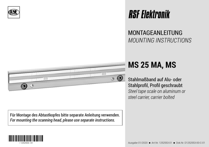
Montage der Maßverkörperung
Montieren Sie die Maßverkörperung gemäß Maßzeichnung
(siehe Seite 3) parallel zur Maschinenführung (M) und
möglichst nahe an der Bearbeitungsebene.
Wir empfehlen eine Nut, einen Anschlag parallel
zur Maschinenführung oder Ähnliches.
Reinigen Sie die Maßverkörperung nach der Montage.
Wir empfehlen ein weiches, fusselfreies, nicht scheuerndes
Tuch und Aceton, Propanol, Ethanol oder andere
hochprozentige alkoholische Reiniger.
Ziehen Sie nun die Schutzfolie ab.
Reinigen Sie die Maßverkörperung nach der Montage.
Wir empfehlen ein weiches, fusselfreies, nicht scheuerndes
Tuch und Aceton, Propanol, Ethanol oder andere
hochprozentige alkoholische Reiniger.
Ausgabe 10/2012 - Art.Nr. 743856-01 - Dok.Nr. D743856-01-B-01 - Technische Änderungen vorbehalten!
Montageanleitung
MS 20, MS 21, MS 25, MS 26 GS
Glasmaßstab auf Stahlprofil
1
Abstandsfolie
Schutzfolie abziehen
Überprüfung der Montage
MS 20, MS 21: Um die Montage zu überprüfen,
empfehlen wir, eine passende elektronische Anbauhilfe
von RSF zu verwenden, die auf die jeweilige Abtasteinheit
und das Ausgangssignal abgestimmt ist (siehe Seite 7).
MS 25, MS 26: Integrierte Anbaukontrolle
über 3-farbige LED (siehe Seite 8).
Überprüfen Sie den Verfahrweg des Maschinen-
tisches in Bezug auf die Messlänge des Messsystems.
Achten Sie darauf, dass die Maschinenanschläge
innerhalb der Messlänge des Messsystems liegen.
Ein Überfahren der Messlänge führt zum Verlust von
Zählsignalen und kann unter Umständen auch zur
Beschädigung des Messsystems führen!
Verlegung des Kabels
Verlegen Sie das Kabel so, dass die minimalen
Biegeradien nicht unterschritten werden.
Wenn die Abtasteinheit am beweglichen Teil der
Maschinenführung angebracht ist, sollte das Kabel in
einer Schleppkette oder Ähnlichem untergebracht werden.
Achtung!
Gerätestecker nur spannungsfrei verbinden!
Steckerstifte nicht berühren! (ESD-Richtlinie)
Sensor-Leitungen: Gesamtkabellänge bis 30 m!
Technische Daten entnehmen Sie bitte unserem Prospekt
MS 2x "Offene Längenmesssysteme mit Einfeld-Abtastung"
Advices for mounting

Generally two mounting surfaces are required (see techn. drawing).
Mounting brackets would be necessary if the scale cannot
be mounted directly onto the slide.

The Linear Encoder must be protected against intense
contamination (thick layer of dust, oil, coolant etc.)
by an additional cover (sheet metal cover or bellows).
Mounting of the measuring scale

A simple way to install the measuring scale is to have a groove
machined in the side of the slide parallel to
the machine guideway (M) according technical drawing (page 3)
and near the machining level.
Place the scale in the groove.
When a machined groove is not available, make sure
that the edge of the scale is parallel to the machine guideway.
After installing the scale, please check it for flatness and parallelism.

Clean the scale after mounting.
We recommend a soft, lintfree, not rubbing cloth and acetone,
propanol, ethanol or another high-percentage alcoholic cleaner.

Remove the protective foil.

After removing the foil, clean the scale if required.
We recommend a soft, lintfree, not rubbing cloth and acetone,
propanol, ethanol or another high-percentage alcoholic cleaner.
Glass scale on steel carrier
Date 10/2012 - Art.Nr. 743856-01 - Dok.Nr. D743856-01-B-01 - Technical adjustments in reserve! 2
shim
Inspection of mounting

To adjust and check the mounting,
we recommend to use a compatible Mounting Controller from
RSF, which is harmonized to the respective encoder type and
output signal (see page 7).

Integrated mounting control via 3-colored LED
(see page 8).

Ensure the encoder measuring length is greater than
the maximum travel of the axis. Make sure dead end
stops are within the measuring length of the encoder.
Moving outside the encoder measuring length will result
in miscounting and may cause damage to the encoder.
Cable management

Position the cable such that the cable bend radius meets
or exceeds the minimum bend radius.

After mounting the encoder head, check the full range
of motion to make sure the cable does not rub, snag
or pinch on assembly components.

Do not connect or disconnect the encoder head
to the Digital Readout or Control while power is on!

Do not touch the connector pins! (ESD-directive)

With sensor-lines the maximum cable length is 30 m!
Mounting of the encoder head

After removing the protective tape, clean the encoder head.
We recommend a soft, lintfree, not rubbing cloth and
acetone, propanol, ethanol or another high-percentage
alcoholic cleaner.

Note that the minimum-thread engagement length
of the mounting screws must be 3 mm.

Ligthly tighten the mounting screws.

Use the mounting shim (thickness 0.75 mm) to set
the proper air gap between the encoder head and
the scale.

Adjust the encoder as per the given tolerance.

Tighten the mounting screws with a tightening torque
of 1.2 Nm.

Remove the shim.

Clean the scale again if required.
RSF Elektronik Ges.m.b.H. A-5121 Tarsdorf +43 (0)6278/8192-0 
FAX
+43 (0)6278/ 8192-79 e-mail: info@rsf.at Internet: www.rsf.at
Abmessungen - Montagetoleranzen /
Dimensions - mounting tolerances:
Anbaumöglichkeiten /
mounting possibilities:
3
RSF Elektronik Ges.m.b.H. A-5121 Tarsdorf +43 (0)6278/ 8192-0 
FAX
+43 (0)6278/ 8192-79 e-mail: info@rsf.at Internet: www.rsf.at 4
MS 20, MS 25
Positionierung der Schaltpunkte /
Positioning of the switch points
z.B.: S1: 20 mm vom Beginn der ML (links) S2: 40 mm vor dem Ende der ML (rechts)
Länge X1 = 20 mm + 10 mm = 30 mm Länge X2 = 40 mm + 35 mm = 75 mm
e.g.: S1: 20 mm from the beginning of ML (left) S2: 40 mm from the end of ML (right)
length X1 = 20 mm + 10 mm = 30 mm length X2 = 40 mm + 35 mm = 75 mm
Wichtig! /
Abdeckbänder parallel zur Kante bzw. zur Schaltspur kleben!
Ensure that black cover tapes for switch tracks are parallel to the scale!
Reinigen Sie die Maßverkörperung nach dem Aufkleben der Abdeckbänder.
Wir empfehlen ein weiches, fusselfreies, nicht scheuerndes Tuch und Aceton, Propanol Ethanol, oder andere hochprozentige alkoholische Reiniger.
After affixing the cover tapes, clean the scale.
We recommend a soft, lintfree, not rubbing cloth and acetone, propanol, ethanol or another high-percentage alcoholic cleaner.
MS 21, MS 26
Referenzmarken (RI)-Auswahl /
Reference mark (RI)-select
Positionierung der Schaltpunkte /
Positioning of the switch points
RSF Elektronik Ges.m.b.H. A-5121 Tarsdorf +43 (0)6278/ 8192-0 
FAX
+43 (0)6278/ 8192-79 e-mail: info@rsf.at Internet: www.rsf.at
Schaltsignal-Ausgang /
Switch signal output
5
RSF Elektronik Ges.m.b.H. A-5121 Tarsdorf +43 (0)6278/ 8192-0 
FAX
+43 (0)6278/ 8192-79 e-mail: info@rsf.at Internet: www.rsf.at 6
Stecker LD15 15-polig
Connector LD15
15-pin
* Test = Analogsignal-Umschaltung zur Anbaukontrolle (nur für MS 20, MS 21)
Bei Anlegen von 5 V an den Testpin werden anstatt der Rechteck-Signale
die Testsignale (Differenzstromsignale 11 µAss) auf die Signalausgänge geschaltet.
Bei Version MS 25, MS 26 ist der Testpin NICHT angeschlossen!
*
Test = analog signal switch-over for setup (only for MS 20, MS 21)
By applying +5 V to the test pin, the test signals (sinusoidal micro-current signals 11 µApp)
are switched to the output connector. At version MS 25, MS 26 the test pin is NOT connected!
MS 20, MS 25: S1, S2 = Schaltsignale
MS 20, MS 25: S1, S2 = switch signals
MS 21, MS 26: S1 = bedingt als Schaltsignal verwendbar, S2 = Schaltsignal
MS 21, MS 26:
S1 = conditionally possible for switch signal, S2 = switch signal
** Bei Ausführung ohne Schaltsignale (Version 0) = nc
**
version without switch signals (version 0) = nc
Sensor: Die Sensor-Pins sind im Steckergehäuse auf
die jeweilige Spannungsversorgung gebrückt
The sensor-pins are bridged in the chassis with the particular power supply
Schirm ist zusätzlich mit dem Steckergehäuse verbunden
The shield is connected with the chassis
PIN Belegung (Sicht auf Stiftseite)
Pin assignment
(view on pins)
Steckerbelegung /
Pin assignment
Pin 1 2 3 4 5 6 7 8 9 10 11 12 13 14 15
Spannungssignale
Voltage signals 1 Vpp
nc 0 V
Sensor
nc RI A2 A1 +5 V
Sensor
+5 V 0 V S1** S2** RI A2 A1 Schirm
Shield
Rechtecksignale
über Line Driver
Square-wave signals
via Line Driver
Test*/
nc
0 V
Sensor
US RI T2 T1 +5 V
Sensor
+5 V 0 V S1** S2** RI T2 T1 Schirm
Shield
Ausgangssignale /
Output signals
Rechtecksignale Sinusförmige Spannungssignale 1 Vss
Square wave signals
Voltage signals 1 Vpp
Schirmverbindungen /
Cable shielding
Geschirmtes PUR-Kabel, Ø 4,3 mm
Biegeradius einmalig >10 mm
dauernd > 50 mm
Torsion > 300.000 Zyklen
Schleppkette >5.000.000 Zyklen

Shielded PUR-cable, Ø 4.3 mm

Bending radius fixed mounting > 10 mm
continuous flexing > 50 mm

Torsion > 300.000 cycles

Drag chain > 5.000.000 cycles
RSF Elektronik Ges.m.b.H. A-5121 Tarsdorf +43 (0)6278/ 8192-0 
FAX
+43 (0)6278/ 8192-79 e-mail: info@rsf.at Internet: www.rsf.at 7
Zur einfacheren Kontrolle bietet RSF Elektronik verschiedene Prüfgeräte an, mit deren Hilfe dieser Vorgang schnell und komfortabel durchzuführen ist.
For the easier control RSF offers various signal test boxes. With these test boxes all encoder signals can be quickly and easily checked.
Sinusförmige Spannungssignale 1 Vss /
Voltage signals 1 Vpp
= PG1-U, PG-U
Rechtecksignale /
Square wave signals
= PG1-I, PG2-I
PG1-I / PG1-U:
Alle funktionsrelevanten Signalgrößen werden
mit LCD-Balkenanzeigen dargestellt
(siehe auch Bedienungsanleitung PG1-I bzw. PG1-U
All relevant signals are displayed with LCD-bars
(also in operation manual PG1-Iresp. PG1-U)
Elektronische Anbauhilfen PG für MS 20, MS 21 /
Electronic test/set-up boxes PG for MS 20, MS 21
PG1-I:
PG1-U:
S2
S1
Artikel-Nummer Adapterkabel:
article-number adapter cable:
998200000083
zum
Netzgerät
to power
supply
zum Messsystem
to Linear Encoder
PG2-I:
PG-U:
PG2-I / PG-U
Alle funktionsrelevanten Signalgrössen werden
mit LED´s angezeigt
All relevant signals are displayed with LED's
LED Anzeige / Information
COUNTING (Zählsignale)
(counting signals)
Rot /
red
Spursignale außerhalb der Toleranz
track signals out of tolerance
Grün /
green
Spursignale ok /
track signals ok
REFERENCE (Referenzimpuls)
(reference impulse)
nur beim Überfahren der Referenzmarke
only by passing the reference mark
Rot /
red
RI außerhalb der Toleranz /
RI out of tolerance
Orange RI geringfügig außerhalb der Toleranz
RI slightly out of tolerance
Grün /
green
RI ok
SWITCH TRACK (Schaltsignale)
(switch signals)
nur beim Überfahren des Schaltspur-Abdeckbandes
only by passing the cover tape of the switch track
Grün /
green
Funktion ok /
function ok
RSF Elektronik Ges.m.b.H. A-5121 Tarsdorf +43 (0)6278/ 8192-0 
FAX
+43 (0)6278/ 8192-79 e-mail: info@rsf.at Internet: www.rsf.at 8
Achtung! Bei MS 25, MS 26 ist keine Analogsignal-
Umschaltung zur Anbaukontrolle vorgesehen
At MS 25, MS 26 no analogue-signal switch-over
for mounting control is provided
Überprüfung der Montage: MS 25, MS 26
Mit einer dreifarbigen LED (rot, grün, blau) werden
die Spursignal-Amplituden und der Referenzimpuls angezeigt.
Im Spursignal-Ampiltudenbereich 0,3 Vss bis 1 Vss und
1 Vss bis 1,45 Vss wird eine lineare Mischung von
Rot und Grün angezeigt.
Zusätzlich wird die Spursignal-Amplitude noch
durch "BLINKEN" der LED angezeigt.
*Bei Messsystemen deren Ausgangssignale sinusförmige
Spannungssignale 1 Vss sind, beziehen sich die in der Tabelle
angegebenen Spannungen exakt auf diese Ausgangssignale.
Bei Messsystemen mit rechteckförmigen Ausgangssignalen
(integrierte Interpolation) beziehen sich die in der Tabelle
angegebenen Spannungen auf den Eingang
des integrierten Interpolators.
Via a tricolored LED (red, green, blue) the track-signal amplitude
and the reference pulse are shown.
In the track-signal amplitude-range 0.3 Vpp to 1 Vpp and
1 Vpp to 1.45 Vpp a linear mixture of red and green is shown.
Additionally the track-signal amplitude is shown by "flashing"
of the LED.
* At measuring systems with sinusoidal voltage signals 1 Vpp
the values of the table are exactly referring to these output signals.
At measuring systems with square-wave output signals
(integrated interpolation) the values of the table are referring to
the input of the integrated interpolator.
LED-Anzeige Abtastsignale Hauptspur
RI ist außer Toleranz
RI ist in Toleranz
Hinweis! Die Funktionsanzeige des Referenzmarkensignals wird
bei höheren Verfahrgeschwindigkeiten abgeschaltet,
um ein dauerndes Blinken zu vermeiden. Die Information zu
den Inkrementalsignalen würde sonst nicht mehr dargestellt.
Funktionskontrolle Referenzimpuls (RI)
Beim Überfahren der Referenzmarke
schaltet die LED kurze Zeit auf Blau bzw. Rot
Amplituden-
bereich sin cos
LED
blinkt
LED
Farbe
Anbau
ist …
1,35 V - 1,45 V 5x unzureichend
1,25 V - 1,35 V 4x unzureichend
1,15 V - 1,25 V 3x akzeptabel
1,05 V - 1,15 V 2x gut
0,95 V - 1,05 V 1x optimal
0,85 V - 0,95 V 2x gut
0,75 V - 0,85 V 3x akzeptabel
0,65 V - 0,75 V 4x unzureichend
0,55 V - 0,65 V 5x unzureichend
0,45 V - 0,55 V 6x unzureichend
0,35 V - 0,45 V 7x unzureichend
<0,35 V 8x unzureichend
RI out of tolerance
RI within tolerance
The status display of the reference mark signal is
switched off at higher velocities, in order to avoid permanent blinking.
The information of the incremental signals would otherwise
no longer be displayed.
While passing the reference mark,
the LED switches shortly into blue resp. red
1.35 V - 1.45 V 5x
insufficient
1.25 V - 1.35 V 4x
insufficient
1.15 V - 1.25 V 3x
acceptable
1.05 V - 1.15 V 2x
good
0.95 V - 1.05 V 1x
best
0.85 V - 0.95 V 2x
good
0.75 V - 0.85 V 3x
acceptable
0.65 V - 0.75 V 4x
insufficient
0.55 V - 0.65 V 5x
insufficient
0.45 V - 0.55 V 6x
insufficient
0.35 V - 0.45 V 7x
insufficient
<0.35 V 8x
insufficient

Other manuals for MS 25

1

This manual suits for next models

3

Other RSF Elektronik Media Converter manuals

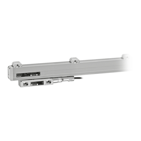
RSF Elektronik MSA 771 User manual

RSF Elektronik

RSF Elektronik MSA 771 User manual

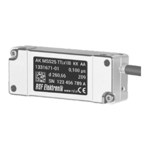
RSF Elektronik AK MSS 25 1 Vss User manual

RSF Elektronik

RSF Elektronik AK MSS 25 1 Vss User manual

RSF Elektronik MSA 871 User manual

RSF Elektronik

RSF Elektronik MSA 871 User manual

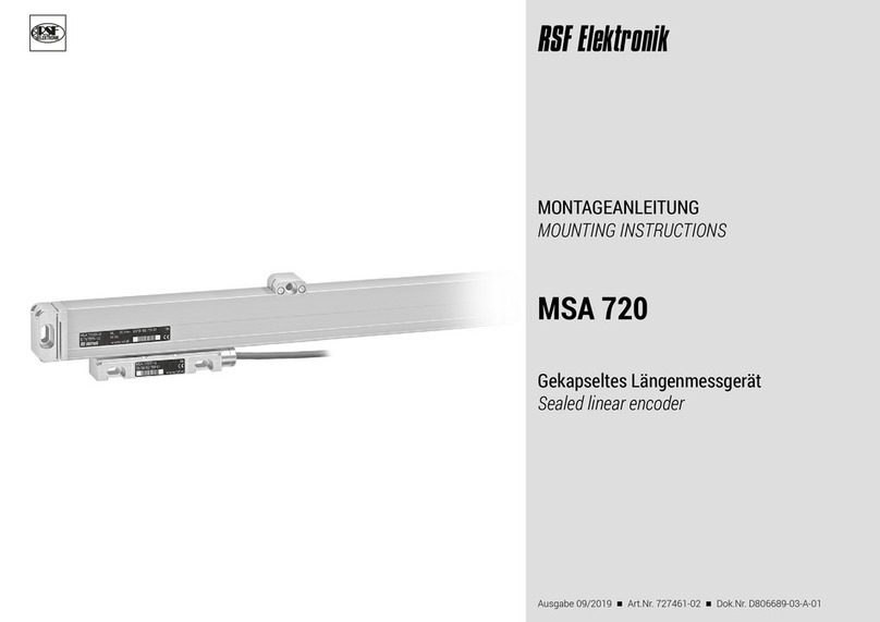
RSF Elektronik MSA 720 User manual

RSF Elektronik

RSF Elektronik MSA 720 User manual

RSF Elektronik MS 25 MA User manual

RSF Elektronik

RSF Elektronik MS 25 MA User manual

RSF Elektronik MSA 820 User manual

RSF Elektronik

RSF Elektronik MSA 820 User manual

RSF Elektronik AK MS 15 User manual

RSF Elektronik

RSF Elektronik AK MS 15 User manual

RSF Elektronik MS 45 MO User manual

RSF Elektronik

RSF Elektronik MS 45 MO User manual

Popular Media Converter manuals by other brands

AJA KONA LHe Installation and operation guide

AJA

AJA KONA LHe Installation and operation guide

Agilent Technologies N4916A Getting started

Agilent Technologies

Agilent Technologies N4916A Getting started

Parkside 109819 Operation and safety notes

Parkside

Parkside 109819 Operation and safety notes

TRENDnet TFC-1000 Quick installation guide

TRENDnet

TRENDnet TFC-1000 Quick installation guide

PR electronics 9116-EMP product manual

PR electronics

PR electronics 9116-EMP product manual

Extron electronics HDP 101 4K user guide

Extron electronics

Extron electronics HDP 101 4K user guide

geratech EGE-12VS manual

geratech

geratech EGE-12VS manual

Kramer VM-3A user manual

Kramer

Kramer VM-3A user manual

Technman 5501 installation guide

Technman

Technman 5501 installation guide

StarTech.com MCM110SC2 instruction manual

StarTech.com

StarTech.com MCM110SC2 instruction manual

Midian Electronics TS-120-VX1 manual

Midian Electronics

Midian Electronics TS-120-VX1 manual

Hama Power 150 Operating	 instruction

Hama

Hama Power 150 Operating instruction

Siemens SINAMICS G120 Applications manual

Siemens

Siemens SINAMICS G120 Applications manual

Omnitron Systems Technology miConverter 10/100 Plus user manual

Omnitron Systems Technology

Omnitron Systems Technology miConverter 10/100 Plus user manual

BBV RS485 StarCard installation guide

BBV

BBV RS485 StarCard installation guide

Moxa Technologies IMC-21A series Hardware installation guide

Moxa Technologies

Moxa Technologies IMC-21A series Hardware installation guide

roco 40411 manual

roco

roco 40411 manual

Moxa Technologies TCC-120 Hardware installation guide

Moxa Technologies

Moxa Technologies TCC-120 Hardware installation guide

manuals.online logo
manuals.online logoBrands
  • About & Mission
  • Contact us
  • Privacy Policy
  • Terms and Conditions

Copyright 2025 Manuals.Online. All Rights Reserved.