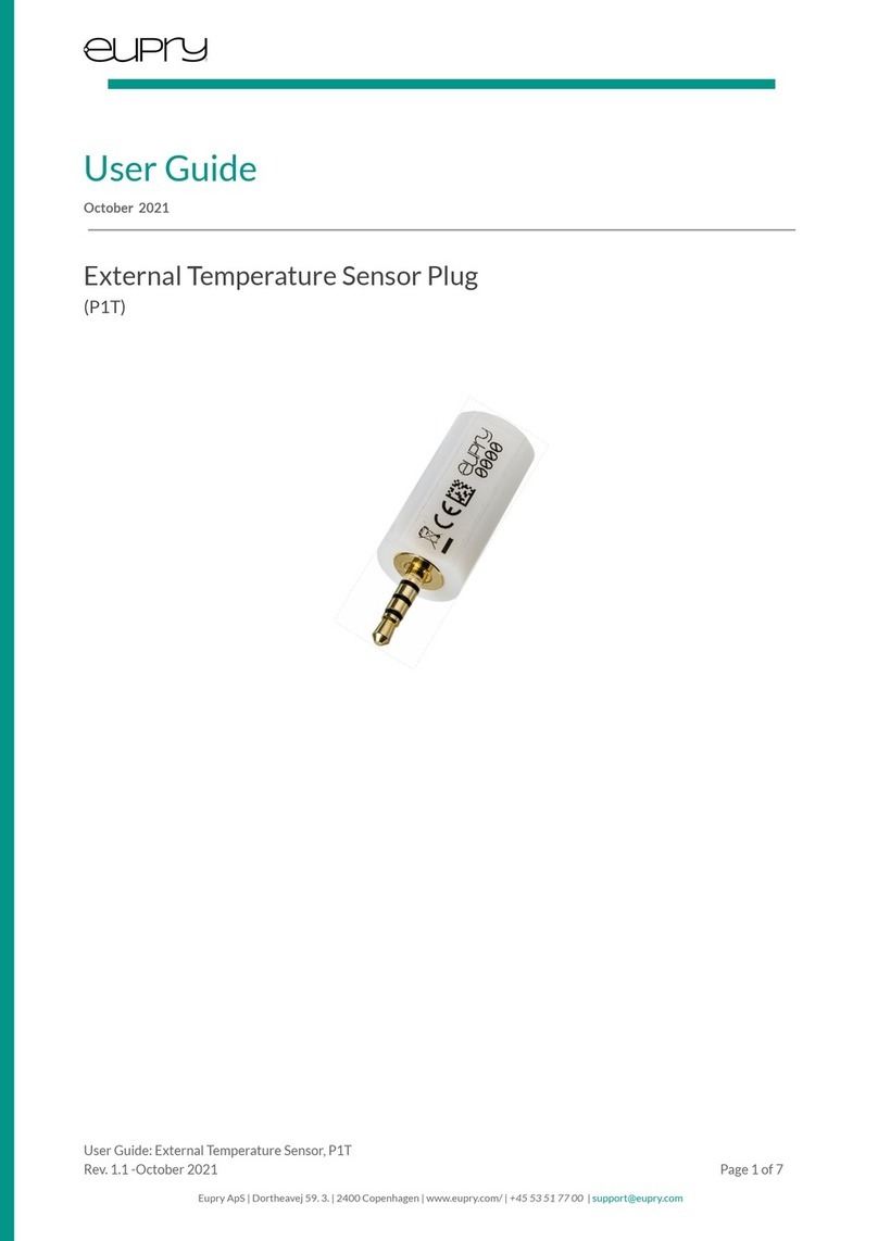
EUPRY P2T User manual

User Guide
June 2022
External Temperature Probe
(P2T)
User Guide: External Sensor, P2T
Rev. 1.2 -June 2022 Page 1 of 7
Eupry ApS | Dortheavej 59. 3. | 2400 Copenhagen | www.eupry.com/ | +45 53 51 77 00 |support@eupry.com

1 Copyrights & Trademarks
Specifications and guides are subject to change without notice. Eupry is a registered trademark of
Eupry ApS. Other brands and product names are trademarks or registered trademarks of their
respective holders.
No part of the specifications and guides may be reproduced in any form or by any means or used to
make any derivative such as translation, transformation, or adaptation without permission from Eupry
ApS. Copyright © 2022 Eupry ApS. All rights reserved.
www.eupry.com
2 Statements
Legal entity:
Eupry ApS
Dortheavej 59, 3.
2400 Copenhagen NV
Denmark
VAT: 30536665
Tlf. +45 53 51 77 00
Mail: hello@eupry.com
Product is certified to CE standard and complies to all relevant CE-standards, as well as RoHs standard.
This equipment has been tested and found to comply with the limits for a Class B digital device, pursuant to part 15 of the
FCC Rules. These limits are designed to provide reasonable protection against harmful interference in a residential
installation. This equipment generates, uses and can radiate radio frequency energy and, if not installed and used in
accordance with the instructions, may cause harmful interference to radio Communications. However, there is no guarantee
that interference will not occur in a particular installation. If this equipment does cause harmful interference to radio or
television reception, which can be determined by turning the equipment off and on, the user is encouraged to try to correct
the interference by one or more of the following measures: —Reorient or relocate the receiving antenna. —Increase the
separation between the equipment and receiver. —Connect the equipment into an outlet on a circuit different from that to
which the receiver is connected. —Consult the dealer or an experienced radio/TV technician for help. CAUTION: Changes or
modifications not expressly approved by Eupry could void the user’s authority to operate this equipment according to part
15 of the FCC rules.
User Guide: External Sensor, P2T
Rev. 1.2 -June 2022 Page 2 of 7
Eupry ApS | Dortheavej 59. 3. | 2400 Copenhagen | www.eupry.com/ | +45 53 51 77 00 |support@eupry.com

3 Content
1 Copyrights & Trademarks 2
2 Statements 2
3 Content 3
4 Introduction 4
5 Specifications 4
6 Setup of Eupry External Sensor 5
7 Product Identification 5
8 Appendix FAQ 6
8.1 I have got multiple alarms during the connection process 6
8.2 I have gotten a new external sensor and now I get more alarms 6
8.3 The light does not turn on when I press the Eupry Button 6
8.4 The logger does not light green when I release the button 6
8.5 Where can I see the ID of the Data Logger and ID of the External Sensor? 6
9 Support 7
10 Revision history 7
User Guide: External Sensor, P2T
Rev. 1.2 -June 2022 Page 3 of 7
Eupry ApS | Dortheavej 59. 3. | 2400 Copenhagen | www.eupry.com/ | +45 53 51 77 00 |support@eupry.com

4 Introduction
The following is a manual for the External Sensor. The unit works with Eupry’s Data Loggers, and all data can be viewed on
the online platform, Eupry Monitoring.
5 Specifications
Temperature Operating Range
-90 °C to +50 °C (-130 °F to 122 °F)
Temperature Resolution
0.03 °C (0.054 °F)
Temperature Accuracy
Dependent on Calibration
Typical Temperature Accuracy
±0.5 °C (±0.9 °F) [@-90 °C to +50 °C]
Thermal Response Time (τ)
9 s
Sensor Type
Digital / PT100
Certifications
CE & ROHS
Identification
Unique GS1 GRAI Code
Max Diameter
16 mm
Cable Length
2.5 m
The flat silicone cable should not be in contact with liquids or be exposed to repeated stress, as this
could damage the cable.
User Guide: External Sensor, P2T
Rev. 1.2 -June 2022 Page 4 of 7
Eupry ApS | Dortheavej 59. 3. | 2400 Copenhagen | www.eupry.com/ | +45 53 51 77 00 |support@eupry.com

6 Setup of Eupry External Sensor
Connecting to your Eupry Data Logger
Connect the External Sensor to the socket on the top face of a Data Logger. Make sure that the sensor is firmly pressed all
the way in until you hear a clicking sound or feel a haptic feedback.
7 Product Identification
Eupry External Sensors have two forms of identification:
Unique serial number
A unique serial number of the External Sensors is written as text on the label of the sensor and can be used to identify the
unit in Eupry’s system.
Unique GRAI code datamatrix
A unique GRAI code identification, which also includes the serial number of External Sensor is placed on the label of the
External Sensor as a data matrix.
The entire GRAI code (GS1 standard) uniquely identifies the sensor internationally and can be used with GRAI compliant
systems.
The last 8 digits of the GRAI-code contains the unique serial number of the sensor and can be used to identify the unit in
Eupry’s system.
User Guide: External Sensor, P2T
Rev. 1.2 -June 2022 Page 5 of 7
Eupry ApS | Dortheavej 59. 3. | 2400 Copenhagen | www.eupry.com/ | +45 53 51 77 00 |support@eupry.com

8 Appendix FAQ
8.1 I have got multiple alarms during the connection process
It is completely normal to get alarms during these processes as the sensors you are connecting are at room temperature
when first plugged in. Be aware that you do not continue to get these alarms.
8.2 I have gotten a new external sensor and now I get more alarms
The new externally calibrated sensors are more accurate and react faster, therefore, it is also normal to get more alarms.
Therefore, it is advisable to expand the alarm limits. However, greyzone alarms are not affected by this.
To change the limits go to eupry.com/logger, and change the critical high and critical low settings for your alarms.
8.3 The light does not turn on when I press the Eupry Button
Look at the user manual for the Data Logger on support.eupry.com.
8.4 The logger does not light green when I release the button
Look at the user manual for the Data Logger on support.eupry.com.
8.5 Where can I see the ID of the Data Logger and ID of the External Sensor?
We have two kinds of barcode labels. The two pictures below illustrate where the ID can be found.
The ID of the Data Logger is the last four digits on the side of the Data Logger. The ID of the sensor is the digits on it (see
figure).
The ID of the Data Logger is the last five digits on the side of the Data Logger. The ID of the sensor is the digits on it (see
figure).
User Guide: External Sensor, P2T
Rev. 1.2 -June 2022 Page 6 of 7
Eupry ApS | Dortheavej 59. 3. | 2400 Copenhagen | www.eupry.com/ | +45 53 51 77 00 |support@eupry.com

9 Support
Please visit the Eupry Support Centre for any support enquiries. This can be accessed by selecting the “Support” button when
logged in to the Eupry Monitoring.
Alternatively, please contact support using the information provided in the footer.
10 Revision history
Revision
Date
Responsible
Change
1.2
03-June-2022
NHP
Changing the temperature range from -196 °C
to +150 °C to -90 °C to +50 °C. Furthermore
adding a disclaimer for the silicone cable.
User Guide: External Sensor, P2T
Rev. 1.2 -June 2022 Page 7 of 7
Eupry ApS | Dortheavej 59. 3. | 2400 Copenhagen | www.eupry.com/ | +45 53 51 77 00 |support@eupry.com
Table of contents
Other EUPRY Temperature Controllers manuals
Popular Temperature Controllers manuals by other brands

Honeywell
Honeywell FIRE-LITE ALARMS W-H355 Installation and maintenance instructions
Sorel
Sorel TDC 1 Installation and operating instructions
Honeywell
Honeywell C7772 Series Product data

PRG
PRG SmartXcan quick start guide
dirna Bergstrom
dirna Bergstrom 1001238153 User handbook
MESCOLI
MESCOLI LK100 instruction manual
