BUSCH 6224/2.0-WL User manual
Product manual │ 13.05.2019
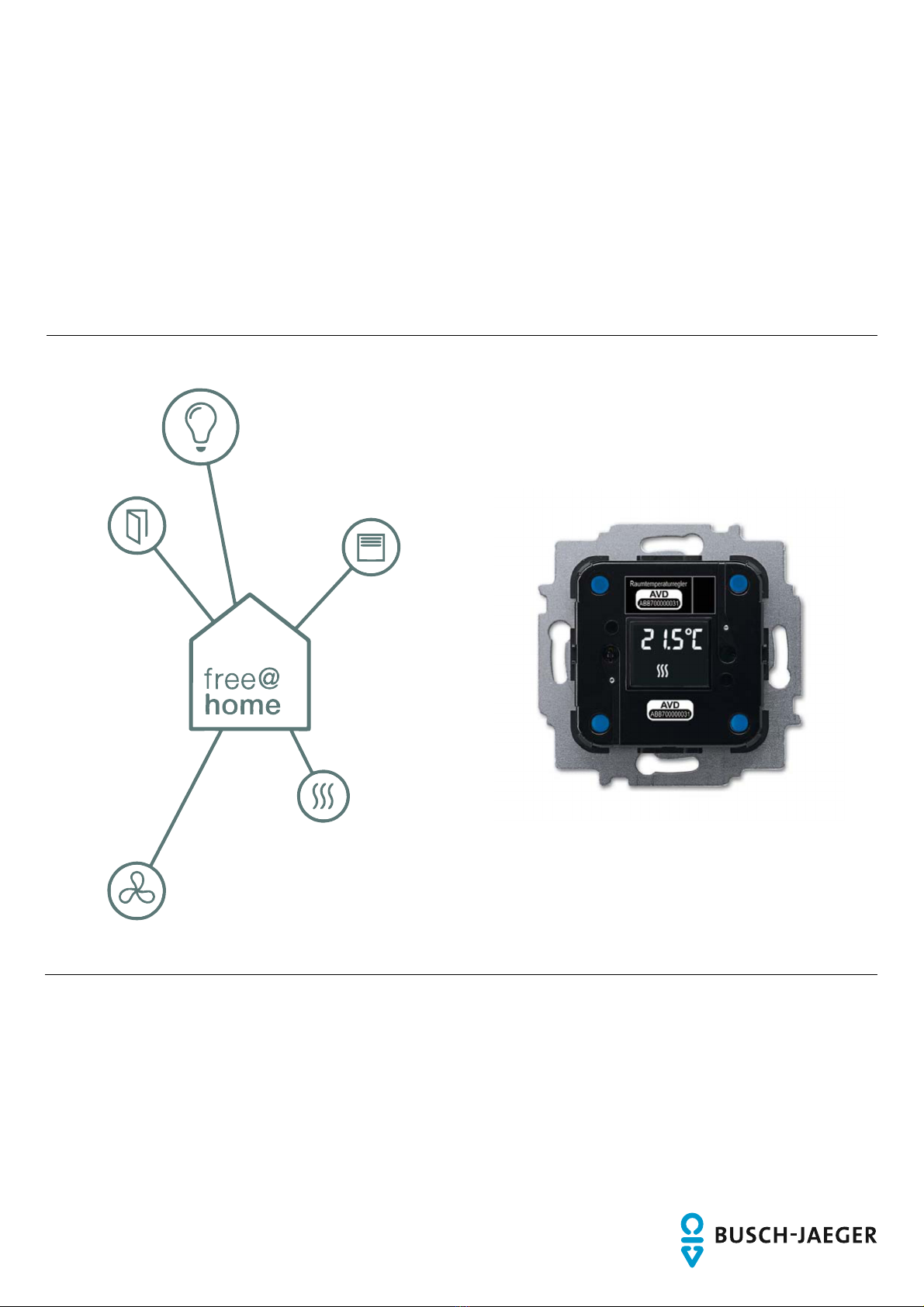
Busch-free@home®
Room temperature controller, wireless
6224/2.0-WL
Room temperature controller/heating actuator, wireless
6224/2.1-WL

Table of contents
Product manual 2CKA001473B9190
│
2
Table of conten ts
1
Information on the manual .......................................................................................................................... 3
2
Safety ......................................................................................................................................................... 4
2.1
Information and symbols used ........................................................................................................ 4
2.2
Intended use ................................................................................................................................... 5
2.3
Improper use ................................................................................................................................... 5
2.4
Target group / Qualifications of personnel ...................................................................................... 5
2.5
Safety instructions ........................................................................................................................... 6
2.6
Environment .................................................................................................................................... 6
3
Setup and function ..................................................................................................................................... 7
3.1
Scope of supply .............................................................................................................................. 7
3.2
Overview of types ........................................................................................................................... 8
3.3
Functions ........................................................................................................................................ 8
3.4
Device overview .............................................................................................................................. 9
4
Technical data .......................................................................................................................................... 10
4.1
Dimensional drawings ................................................................................................................... 11
5
Connection and installation ...................................................................................................................... 12
5.1
Planning instructions ..................................................................................................................... 12
5.2
Safety instructions ......................................................................................................................... 13
5.3
Circuit diagrams ............................................................................................................................ 14
5.4
Installation ..................................................................................................................................... 15
6
Commissioning ......................................................................................................................................... 17
6.1
Coupling of wireless devices with the System Access Point ......................................................... 18
6.1.1
Resetting the wireless device to the factory settings .....................................................................18
6.2
Allocation of devices and definition of channels ............................................................................ 20
6.2.1
Add device ......................................................................................................................................20
6.3
Setting options per channel ........................................................................................................... 23
6.3.1
Parameter settings of room temperature controller .......................................................................24
6.4
Links .............................................................................................................................................. 26
6.4.1
Linking actuator and sensor ...........................................................................................................26
7
Update ...................................................................................................................................................... 27
8
Operation ................................................................................................................................................. 28
8.1
Displays / messages ..................................................................................................................... 30
9
Maintenance ............................................................................................................................................. 31
9.1
Cleaning ........................................................................................................................................ 31
10
Notes ........................................................................................................................................................ 32
11
Index ........................................................................................................................................................ 33

Information on the manual
Product manual 2CKA001473B9190
│
3
1 Information on the manual
Please read this manual carefully and observe the information it contains. This will assist you in
preventing injuries and damage to property, and ensure both reliable operation and a long
service life for the device.
Please keep this manual in a safe place.
If you pass the device on, also pass on this manual along with it.
Busch-Jaeger accepts no liability for any failure to observe the instructions in this manual.
If you require additional information or have questions about the device, please contact Busch-
Jaeger or visit our Internet site at:
www.busch-jaeger.de/freeathome

Safety
Product manual 2CKA001473B9190
│
4
2 Safety
The device has been constructed according to the latest valid regulations governing technology
and is operationally reliable. It has been tested and left the factory in a technically safe and
reliable state.
However, residual hazards remain. Read and adhere to the safety instructions to prevent
hazards of this kind.
Busch-Jaeger accepts no liability for any failure to observe the safety instructions.
2.1 Information and symbols used
The following Instructions point to particular hazards involved in the use of the device or provide
practical instructions:
Danger
Risk of death / serious damage to health
– The respective warning symbol in connection with the signal word "Danger"
indicates an imminently threatening danger which leads to death or serious
(irreversible) injuries.
Warning
Serious damage to health
– The respective warning symbol in connection with the signal word "Warning"
indicates a threatening danger which can lead to death or serious
(irreversible) injuries.
Caution
Damage to health
– The respective warning symbol in connection with the signal word "Caution"
indicates a danger which can lead to minor (reversible) injuries.
Attention
Damage to property
– This symbol in connection with the signal word "Attention" indicates a
situation which could cause damage to the product itself or to objects in its
surroundings.
NOTE
This symbol in connection with the word "Note" indicates useful tips and
recommendations for the efficient handling of the product.
This symbol alerts to electric voltage.

Safety
Product manual 2CKA001473B9190
│
5
2.2 Intended use
This device is a room temperature controller for decentralized flush-mounted installation. The
room temperature controller (with bus coupler) is suitable for the control of conventional heating
and cooling systems.
The device is intended for the following:
■ Operation according to the listed technical data
■ Installation in dry interior rooms and suitable flush-mounted boxes
■ Use with the connecting options available on the device
The intended use also includes adherence to all specifications in this manual.
2.3 Improper use
Each use not listed in Chapter 2.2 “Intended use“ on page 5 is deemed improper use and can
lead to personal injury and damage to property.
Busch-Jaeger is not liable for damages caused by use deemed contrary to the intended use of
the device. The associated risk is borne exclusively by the user/operator.
The device is not intended for the following:
■ Unauthorized structural changes
■ Repairs
■ Outdoor use
■ The use in bathroom areas
2.4 Target group / Qualifications of personnel
Installation, commissioning and maintenance of the device must only be carried out by trained
and properly qualified electrical installers.
The electrical installer must have read and understood the manual and follow the instructions
provided.
The electrical installer must adhere to the valid national regulations in his/her country governing
the installation, functional test, repair and maintenance of electrical products.
The electrical installer must be familiar with and correctly apply the "five safety rules" (DIN VDE
0105, EN 50110):
1. Disconnect
2. Secure against being re-connected
3. Ensure there is no voltage
4. Connect to earth and short-circuit
5. Cover or barricade adjacent live parts

Safety
Product manual 2CKA001473B9190
│
6
2.5 Safety instructions
Danger - Electric voltage!
Electric voltage! Risk of death and fire due to electric voltage of 100 … 240 V.
Dangerous currents flow through the body when coming into direct or indirect
contact with live components. This can result in electric shock, burns or even
death.
■ Work on the 100 … 240 V supply system may only be performed by
authorised and qualified electricians.
■ Disconnect the mains power supply before installation or dismantling.
■ Never use the device with damaged connecting cables.
■ Do not open covers firmly bolted to the housing of the device.
■ Use the device only in a technically faultless state.
■ Do not make changes to or perform repairs on the device, on its components
or its accessories.
Caution! - Risk of damaging the device due to external factors!
Moisture and contamination can damage the device.
■ Protect the device against humidity, dirt and damage during transport,
storage and operation.
2.6 Environment
Consider the protection of the environment!
Used electric and electronic devices must not be disposed of with domestic
waste.
– The device contains valuable raw materials which can be recycled.
Therefore, dispose of the device at the appropriate collecting depot.
All packaging materials and devices bear the markings and test seals for proper disposal.
Always dispose of the packaging material and electric devices and their components via the
authorized collecting depots and disposal companies.
The products meet the legal requirements, in particular the laws governing electronic and
electrical devices and the REACH ordinance.
(EU Directive 2012/19/EU WEEE and 2011/65/EU RoHS)
(EU REACH ordinance and law for the implementation of the ordinance (EC) No.1907/2006).
Setup and function
Product manual 2CKA001473B9190
│
7
3 Setup and function
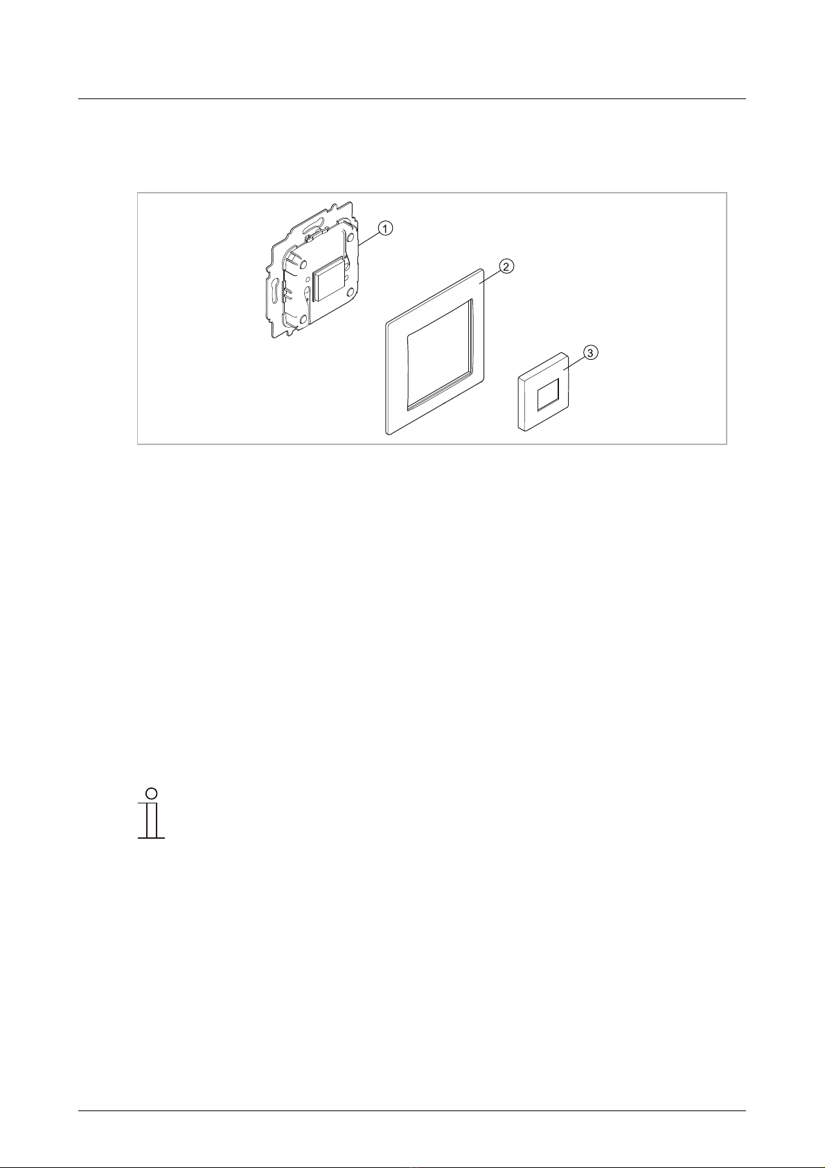
Fig. 1: Product overview
[1] Flush-mounted insert
[2] Cover frame (not included in scope of delivery)
[3] Cover plate (not included in scope of delivery)
This device is a room temperature controller for decentralized flush-mounted installation.
The room temperature controller is suitable for the control of conventional heating and cooling
systems.
The devices are preconfigured and must be parameterised for the use of the functions.
At initial commissioning the device should not be used for at least 3 hours. The calibration of the
device starts automatically after this rest period.
3.1 Scope of supply
The scope of supply only contains the flush-mounted insert [1]. It must still be completed with a
cover frame [2] and a cover plate [3].
Notice
Additional information about the switch ranges is available in the electronic
catalogue (www.busch-jaeger-catalogue.com).

Setup and function
Product manual 2CKA001473B9190
│
8
3.2 Overview of types
Article no. Product name Sensor
channels Actuator
channels Switching
load
6224/2.0-WL Room temperature
controller, wireless 1
0
6224/2.1-WL Room temperature
controller/heating
actuator, wireless 1
1
1 x 3680 W
Table 1: Overview of types
3.3 Functions
The following table provides an overview of the possible functions and applications of the
device:
Icon of the user
interface Information
Name: Room temperature controller
Type: Actuator
Made available by: Room temperature controller
Function: Controls Busch-free@home® heating
actuators
Table 2: Overview of functions
Setup and function
Product manual 2CKA001473B9190
│
9
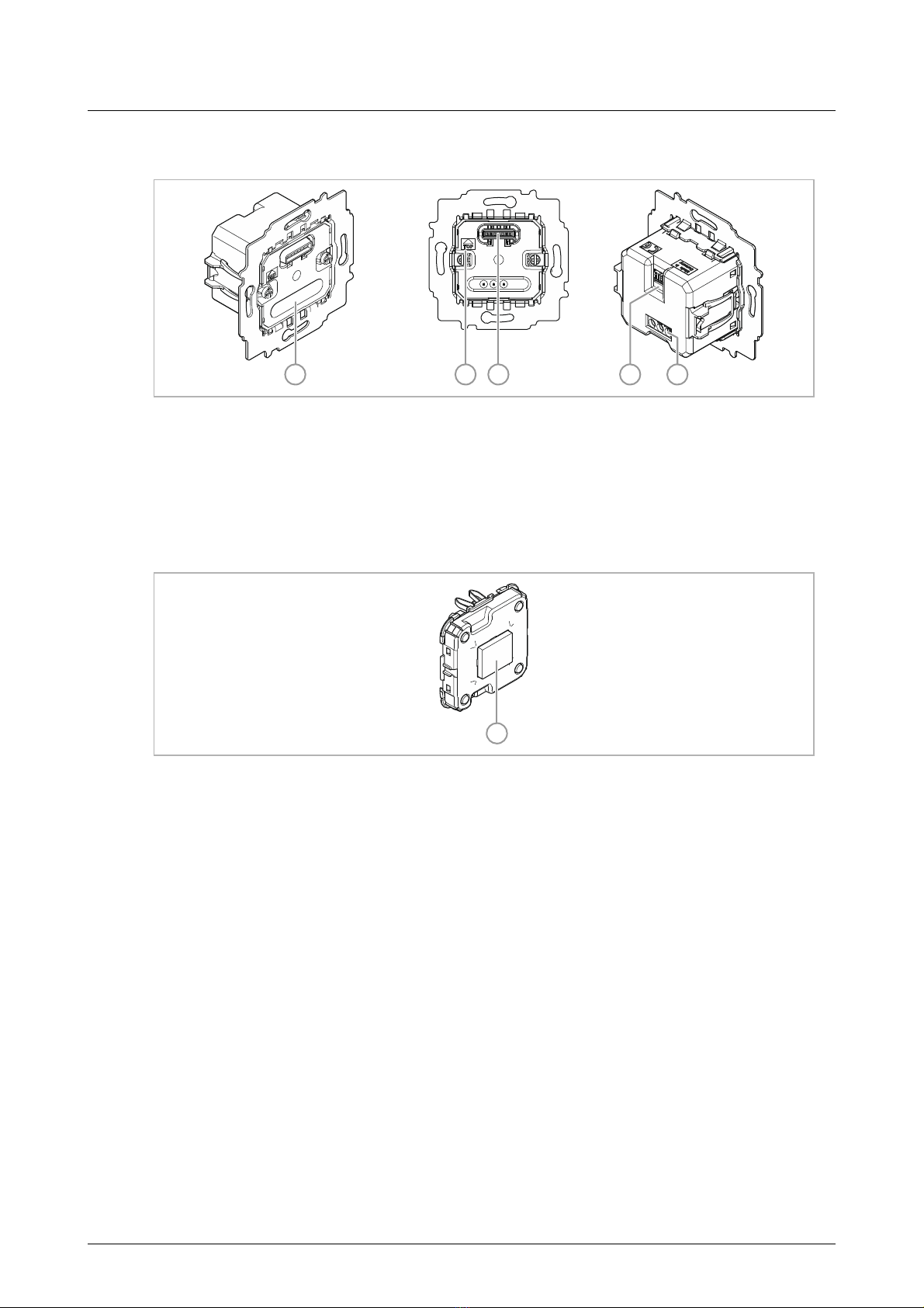
3.4 Device overview
23 451
Fig. 2: Device overview of room temperature controller
[1] Phase sensing L
[2] Mark TOP
[3] Multi-point connector for sensor
[4] Spring plug-in terminal for connecting an external temperature sensor
[5] Bottom terminal block
1
Fig. 3: Sensor
[1] Sensor with display

Technical data
Product manual 2CKA001473B9190
│
10
4 Technical data
Designation Value
Operating voltage 230 V AC, 50/60 Hz
Connection
L, N (option), inputs and outputs non-
floating
Screw-type terminal:
2 x 2.5 mm² rigid;
2 x 1.5 mm² flexible
Claw With protective cover and reset (optionally
removable)
Transmission protocol free@home wireless
Transmission frequency 2.400 - 2.483 GHz
Maximum transmission power
WL (wireless) < 15 dBm
Switching cycles > 100 000
Power consumption < 1 W
Maximum load 1gang switch actuator:
1 x 16 A ohmic load
Protection rating IP20
Ambient temperature -5°C to +45°C
Storage temperature -20°C to +70°C
Temperature sensor of external room temperature
controller 6226/T (Option)
Table 3: Technical data
This manual suits for next models
1
Table of contents
Popular Temperature Controllers manuals by other brands


SMC Networks
SMC Networks Thermo-con INR-244-639 Operation manual

eltherm
eltherm Ex-TC It Series operating instructions

Omron
Omron C200H-TV Series Operation manual

industrie technik
industrie technik CA1 instructions

KRAL
KRAL EET 32 operating instructions

dixell
dixell XR420C Installing and operating instructions