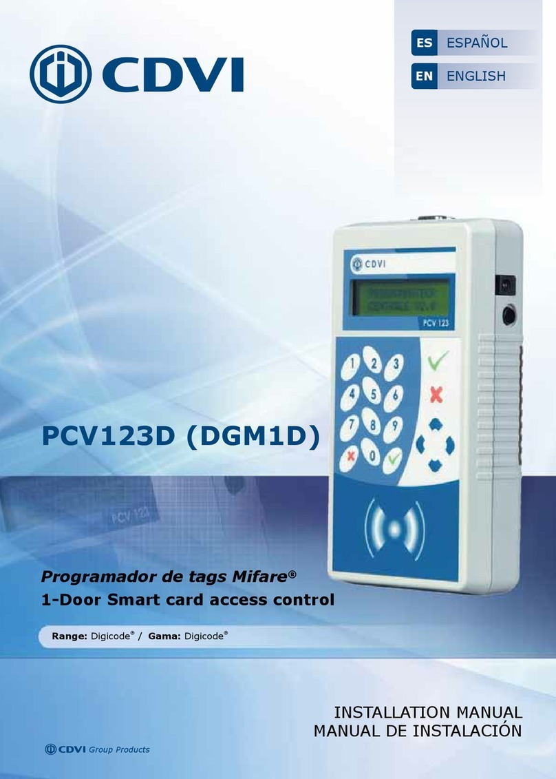
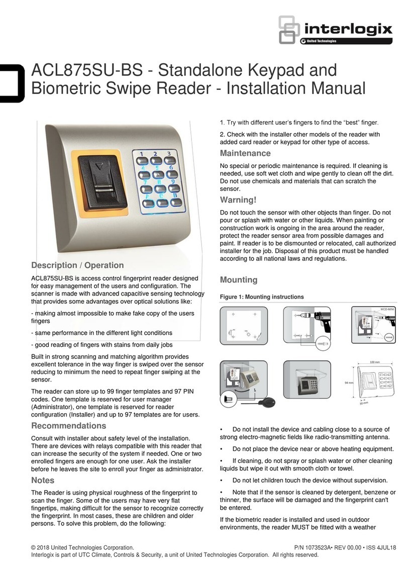
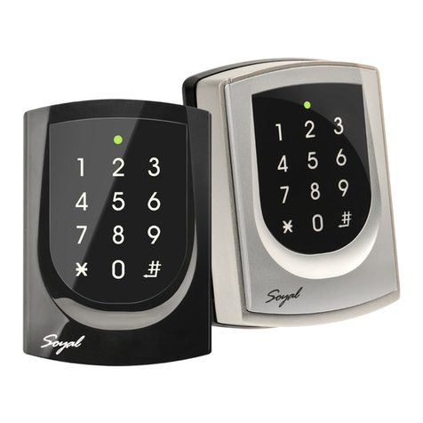
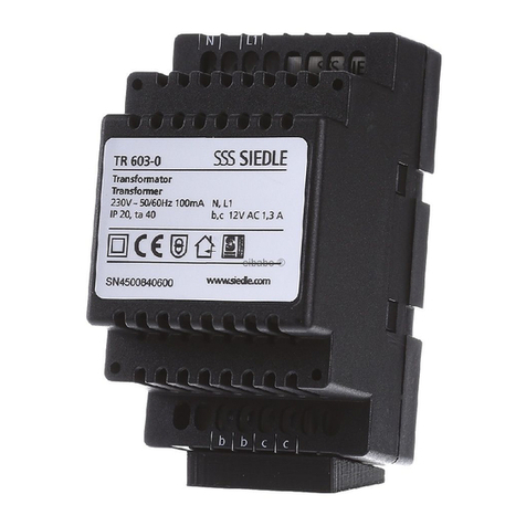
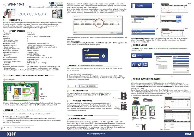
EURA AC-30C7 Parts list manual

ACCESS CONTROL
User manual
and guarantee card
AC-30C7

TABLE OF CONTENTS
1. Device characteristics ..................................................................................................................4
2. set content.........................................................................................................................................4
3. Device construction.......................................................................................................................4
4. Device installation anD connection Diagram..................................................................... 5
5. Device operation ............................................................................................................................. 7
5.1. entrance ....................................................................................................................................... 7
5.2. Door inDicator .......................................................................................................................... 7
5.3. aDDitional functions..............................................................................................................8
5.3.1. egress button ..................................................................................................................8
5.3.2. Door magnet ....................................................................................................................8
5.3.3. Door bell............................................................................................................................8
5.4. entering the programming moDe.....................................................................................8
5.4.1. entering the programming moDe witha use of master coDe....................8
5.4.2. entering the programming moDewith a use ofmaster carD ...................8
5.5. potential problemswith coDes.........................................................................................8
5.5.1. losing master coDe ........................................................................................................8
5.5.2. typing wrong coDes......................................................................................................8
5.5.3. general remarks about coDes .................................................................................8
6. programming moDe........................................................................................................................8
6.1. access moDe setting.................................................................................................................8
6.2. master coDe moDification....................................................................................................9
6.3. setting the length ofa master coDe...............................................................................9
6.4. aDDing master carDs ..............................................................................................................9
6.5. aDDing user carDsanD coDes to zone 1 .........................................................................10
6.5.1. aDDing user carD + coDe to zone 1..........................................................................10
6.5.2. aDDing user coDeto zone 1.......................................................................................10
6.5.3. group user carDaDDing for zone 1 ......................................................................10
6.6. aDDing user carDsanD coDes to zone 2..........................................................................11
6.6.1. aDDing user carD + coDeto zone 2..........................................................................11
6.6.2. aDDing user coDeto zone 2.......................................................................................11
6.7. Deleting carDs anD coDes.....................................................................................................11
6.8. unlocking time setting........................................................................................................ 12
6.8.1. unlocking time setting for zone 1........................................................................ 12
6.8.2. unlocking time setting for zone 2....................................................................... 12
6.9. anti-sabotage function ...................................................................................................... 12
6.10. restoring to the Default settings................................................................................ 12
7. table with programming commanDs summary.................................................................13
8. technical Data................................................................................................................................. 14
warranty...............................................................................................................................................15

3
INITIAL REMARKS
Before assembling, wiring and setting up of device the user should carefully
read given manual. In case of any troubles with understanding the content
the user should contact the producer. Unassisted assembling and start of
the device can be done only with the use of proper tools. However, it is highly
advised to set up a device by qualied personnel.
The producer is not responsible for damages made during incorrect set-up
or maintenance or in case of any unassisted repairs or modications.

4
1. DEVICE CHARACTERISTICS
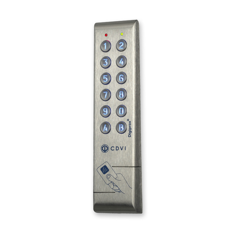
Access control AC-30C7 is used in security system. The device is equipped with two relay
outputs than can be used to release the lock. All functionas are programmed with a use of
numerical mechanical keypad. Aer programming of device there is a possibility to activate
unlocking function by three methods:
- Unlocking with the use of proximity card only,
- Unlocking with the use of combined proximity card and 4-digit code,
- - unlocking with a use of either proximity card or 4-digit code.
Access control is closed in vandalproof andwaterproof (IP55) casing that enablesthe installa-
tion in any place, both outdoors and indoors. At the front of the device there is a mechanical
numerical keypad. At the back there are wires to connect with lock, power supply and other
optional devices.
2. SET CONTENT
Elements included in the set:
- Access control,
- Mounting screws,
- Spline tool.
3. DEVICE CONSTRUCTION
Fig. 1 presents elements of the device AC-30C7.
Door indicator
Matrix
keypad
Antenna
Case screw
Mode indicator
Fig. 1. Construction of AC-30C7

5
Access control is equipped with two relay outputs that can be used to unlock the door. The
devices works either with normal locks (NO/COM joints) or reversed locks (NC/COM).
4. DEVICE INSTALLATION AND CONNECTION DIAGRAM
AC-30C7 should be surface mounted. Before installation, position the location where the
controller unit is to be mounted, then go through the following steps:
1. 0pen the controller by loosening and removing the back case screw at the bottom using
the spline tool. Back case should be moved a few millimeters up and then rotated about 20
degrees and removed.
Fig. 2. Removing the back case of access control
2. Use the provided drilling template accurately locate and drill the required holes, the four
drilling holes are marked „B”.

6
Screws
System wiring
Screw anchors
Fig. 3. Installation of AC-30C7
3. Place the four screw anchors.
4.Connected accurately the system wiring 8S perthe label enclosed on the rear.
1. Red
2. Black
3. Brown
4. Grey
5. Orange
6. Pink
7. Green
8. Purple
9. Blue
10. Green/White
11. Purple/White
12. Blue/White
13. Yellow
14. White
15. Shielding line
Power DC Input
AC Input
Supply
DoorMagnet
Shield ground
Door
Bell
Button1
Button2
Fig. 4. Wiring diagram ofAC-30C7
5. Use the screws provided to mount the back case on the wall, be sure to draw the wiring
through the large canter hole in back case, and keep it level.
6.Put the unit on the back case and screw it on by using the spline tool.

7
NOTES
1. All additional components shown on wiring diagram (lock, door bell, button) are not in-
cluded in the set.
2. Diode D1 should be connected only when lock is DC power supplied.
3. All wires that are not used during installation should be isolated.
5. DEVICE OPERATION
The device is equipped with two relay outputs, enabling the user to control two zones and
door bell output.
Zones specications:
a) I ZONE
- 1000 users,
- Three options to unlock:
•Access with the use of proximity card,
•Access with the use of proximity card or code,
•Access with the use of proximity card and code.
b) II ZONE
- 10 zones.
c) Door bell extension possibility.
5.1. ENTRANCE
Lock can be released depending on the chosen option. The steps of unlocking are presented
below.
To release lock with a use of proximity card the user must move the card in front of the card
reader. If the card is correct door indicator will turn green (zone 1) or red (zone 2) and a short
double beep will be heard. If the card is not correct – the series of 4 beeps will appear.
To release lock with a use of proximity card or code the user must move the card in front of
the card reader / type the code on the keypad. If the card / code is correct door indicator will
turn green (zone 1) or red (zone 2) and a short double beep will be heard. If the card / code is
not correct – the series of 4 beeps will appear.
To release the lock with he use of proximity card and code the user must:
a. At rst must move the card in front of the card reader (if the card is correct a short double
beep will be heard. If the card is not correct – the series of 4 beeps will appear) and type
the code on the keypad. If the code is correct door indicator will turn green (zone 1) or
red (zone 2) and a short double beep will be heard. If the card is not correct – the series
of 4 beeps will appear.
b. At rst type the code on the keypad (if the code is correct a short double beep will be
heard. If the code is not correct – the series of 4 beeps will appear) and then move the
card in front of the card reader. Indicator will turn green (zone 1) or red (zone 2) and a
short double beep will be heard.
5.2. DOOR INDICATOR
Door indicator informs the user in which zone the lock was released.
Door
indadicator A. When the user releases the lock from zone 1 – the indi-
cator turns green
B. When the user releases the lock from zone 2 – the indi-
cator turns red
Fig. 5

8
5.3. ADDITIONAL FUNCTIONS
5.3.1. EGRESS BUTTON
It is possible to connect additional egress button to both zones 1 and 2. The details are given
on the wiring diagram (g. 4).
5.3.2. DOOR MAGNET
The device can detect the closed door – aer opening and closing the door the device blocks
the lock even if the set unlocking time is longer. The details are given on the wiring diagram
(g. 4).
5.3.3. DOOR BELL
The user can connect the door bell to the device. The details are given on the wiring diagram
(g. 4). To activate the bell the user must press button *.
5.4. ENTERING THE PROGRAMMING MODE
5.4.1. ENTERING THE PROGRAMMING MODE WITHAUSE OF MASTER CODE
To enter the setting mode the user must double type master code. The default code is
1234. Mode indicatorwill turn red and long beep will be heard informing about operation
success. Press the button #to quit the setting mode
5.4.2. ENTERING THE PROGRAMMING MODEWITH A USE OFMASTER CARD
To enter the setting mode the user must move the master card in front of the reader. Mode
indicator will turn red and long beep will be heard informing about operation success. Repe-
ating this operation results in leaving the setting mode - mode indicator will turn green and
two shot beeps will be heard informing about operation success.
5.5. POTENTIAL PROBLEMS WITH CODES
5.5.1. LOSING MASTER CODE
In case of losing master code the device’s power supply should be cut o and the button #
must be pressed. Then the device should be powered on again and aer few beeps appear
the master code will come back to the default – 1234.
5.5.2. TYPING WRONG CODES
In case oftyping three incorrect codes or moving three incorrect cards in a rowlong beep will
appear and the device will be blocked for 60s.
5.5.3. GENERAL REMARKS ABOUT CODES
User code must be dierent from the master code. Codes for zone 1 must be dierent from
codes for zone 2.
6. PROGRAMMING MODE
6.1. ACCESS MODE SETTING
To enter the setting mode the user must double type master code. Mode indicator will turn
red and long beep will be heard informing about operation success.
To enter access mode the user must press the button *and 0, the mode indicator will ash
red. The user should choose proper access option by typing keys from the table below:

9
00 Access with the use of proximity card
01 Access with the use of proximity card or code
02 Access with the use of proximity card and code
Aer typing proper combination of keys the mode indicator will turn red and a long beep will
be heard – settings were saved properly.
Press the button #to quit the setting mode.
6.2. MASTER CODE MODIFICATION
To enter the setting mode the user must double type master code. Mode indicator will turn
red and long beep will be heard informing about operation success.
To modify the master code the user must press the button *and 3- the mode indicator will
ash red and input twice a new 4-digit code – a short and a long beep will be heard – settings
were saved properly.
Press the button #to quit the setting mode.
6.3. SETTING THE LENGTH OFA MASTER CODE
To enter the setting mode the user must double type master code. Mode indicator will turn
red and long beep will be heard informing about operation success.
To modify length of a master code the user must press the button *and 9- the mode
indicator will ash red.
Then the user must press 0and 4– a short single beep will appear, mode indicator will start
ashing red – and type the number corresponding to the desired new code length (typing
2 will set code as a 2-digit code). If the single short beep appears, the settings were saved
successfully. If three short beeps appear, the desired code length corresponds to the already
existing one.
Press the button #to quit the setting mode.
NOTE
Changing the master code’s length will automatically delete all saved codes from the device
memory.
6.4. ADDING MASTER CARDS
To enter the setting mode the user must double type master code. Mode indicator will turn
red and long beep will be heard informing about operation success.
Then, to add master card for zone 1 the user should press buttons *and 7. If the mode
indicator:
-Flashes green – there is no master card in the device memory – the user can proceed to
the next step,
Turns red – there already exists a master card in the device memory – before proceeding to
the next step the user should double press the button *to delete existing data – as soon as
mode indicator ashes green the user can proceed to the next step.
The next step is adding the new card – the user should move the new card in front of the
reader until the long beep is heard and mode indicator turns red – the card was added suc-
cessfully.
Press the button #to quit the setting mode.

10
6.5. ADDING USER CARDS AND CODES TO ZONE 1
6.5.1. ADDING USER CARD + CODE TO ZONE 1
To enter the setting mode the user must double type master code. Mode indicator will turn
red and long beep will be heard informing about operation success.
Then to add the new user to zone 1 the number from the range 000-999 should be
typed – door indicator will turn green and mode indicator will ash red.
Note
If the door indicator turns red and mode indicator ashes red – chosen number is already
added to the device memory. Double pressing the button *results in deleting code for this
number. Aer door indicator turns green (conrming deleting the old code) the user can add
a new one.
Then the user must move the card in front of the reader (long beep appears and mode indi-
cator ashes red) and type the new code (of the same length as existing master code). If the
long beep appears and mode indicatorturns red, the settingswere saved successfully.Above
steps must be repeated for adding each new user.
Press the button #to quit the setting mode.
6.5.2. ADDING USER CODE TO ZONE 1
To enter the setting mode the user must double type master code. Mode indicator will turn
red and long beep will be heard informing about operation success.
Then to add the new usercode buttons *and 9 should be pressed - mode indicator ashes
red. Then the user should press buttons 0and 2– short single beep appears and mode
indicator turns red. The next step is choosing the number from the range 000-999 –
double short beep appears, and typing new code - of the same length as existing master
code. If the long beep appears, settings were saved successfully.
Press the button #to quit the setting mode.
Note
If the chosen user already exists – the device will act in the same way, and new settings will
substitute previous ones.
6.5.3. GROUP USER CARD ADDING FOR ZONE 1
To enter the setting mode the user must double type master code. Mode indicator will turn
red and long beep will be heard informing about operation success.
Then to add the new user cards in group buttons *and 9should be pressed - mode in-
dicator ashes red. Then the user should press buttons 0and 1– short single beep ap-
pears and mode indicator turns red. The next step is choosing the number from the range
000-999 – single beep appears and typing the number of desired users that need to
be added (e.g. typing 050 will result in adding 50 cards for 50 next users)*. Aer short single
beep appears each card must be moved in front of the reader – aer adding single card there
appears at rst short beep and then a long beep.
Press the button #to quit the setting mode.
*the user should remember to keep 3 digits of a code – if the number is smaller than 100 it
should be preceded by 0(for numbers 10-99) or 00 (for numbers 0-9).

11
6.6. ADDING USER CARDSAND CODES TO ZONE 2
6.6.1. ADDING USER CARD + CODE TO ZONE 2
To enter the setting mode the user must double type master code. Mode indicator will turn
red and long beep will be heard informing about operation success.
Then to add the new user to zone 2 the buttons *and 4should be pressed – mode indi-
cator ashes red - and number from the range 00-09 should be typed – door indicator
will turn green.
Note
If the door indicator turns red – chosen number is already added to the device memory. Do-
uble pressing the button * results in deleting code for this number. Aer door indicator
turns green (conrming deleting the old code) the user can add a new one.
Then the user must move the card in front of the reader (short and long beep appear) and
type the new code (of the same length as existing master code). If the long beep appears,
door indicator disappears and mode indicatorturns red, the settings were saved successful-
ly. Above steps must be repeated for adding each new user.
Press the button #to quit the setting mode.
6.6.2. ADDING USER CODE TO ZONE 2
To enter the setting mode the user must double type master code. Mode indicator will turn
red and long beep will be heard informing about operation success.
Then to add the new usercode buttons *and 9 should be pressed - mode indicator ashes
red. Then the user should press buttons 0and 3– short single beep appears and mode
indicator turns red. The next step is choosing the number fromthe range 00-09 – double
short beep appears, and typing newcode - of the same length as existing master code. If the
short and long beep appear, settings were saved successfully.
Press the button #to quit the setting mode.
Note
Ifthe chosen user alreadyexists – the device will act inthe same way, and new settings will substitute
previous ones.
6.7. DELETING CARDS AND CODES
To enter the setting mode the user must double type master code. Mode indicator will turn red
and long beep will be heard informing about operation success.
Then to delete the code / card buttons *and 8 should be pressed - mode indicator ashes red.
Then the user should double click button 8– if the long sound appears, the cards were deleted
successfully.
Press the button #to quit the setting mode.

12
6.8. UNLOCKING TIME SETTING
6.8.1. UNLOCKING TIME SETTING FOR ZONE 1
To enter the setting mode the user must double type master code. Mode indicator will turn
red and long beep will be heard informing about operation success.
Then to changethe unlocking time forzone 1 buttons *and 1should be pressed - mode in-
dicator ashes red. The next step is choosing the number from the range 00-99 – chosen
number corresponds to the desired unlocking time in seconds (e.g. typing 04 means chan-
ging unlocking time to 4s). If the mode indicator turns red and long beep appears, settings
were saved successfully. In case of choosing value 00 – moving card in front of the reader
or typing code is necessary to both release and close the lock.
Press the button #to quit the setting mode.
6.8.2. UNLOCKING TIME SETTING FOR ZONE 2
To enter the setting mode the user must double type master code. Mode indicator will turn
red and long beep will be heard informing about operation success.
Then to changethe unlocking time forzone 2 buttons *and 6should be pressed - mode in-
dicator ashes red. The next step is choosing the number from the range 00-99 – chosen
number corresponds to the desired unlocking time in seconds (e.g. typing 04 means chan-
ging unlocking time to 4s). If the mode indicator turns red and long beep appears, settings
were saved successfully. In case of choosing value 00 – moving card in front of the reader
or typing code is necessary to both release and close the lock.
Press the button #to quit the setting mode.
6.9. ANTI-SABOTAGE FUNCTION
In-build speaker will generate long sound for 60s in case of high light intensity detection by
photo-optic sensor. It can be stopped by typing master code.
To enter the setting mode the user must double type master code. Mode indicator will turn
red and long beep will be heard informing about operation success.
Then to change anti-sabotagefunction settings buttons *and 6should be pressed - mode
indicator ashes red. The next step is pressing buttons 0and 1– if the mode indicator
turns red and long beep appears, anti-sabotage alarm is on.
To turn the alarm o buttons *and 6 should be pressed (mode indicator ashes red). Then
to buttons 0and 2should be pressed - if the mode indicator turns yellow and long beep
appears, anti-sabotage alarm is o.
Press the button #to quit the setting mode.
6.10. RESTORING TO THE DEFAULT SETTINGS
To enter the setting mode the user must double type master code. Mode indicator will turn
red and long beep will be heard informing about operation success.
Then to restore the device to its default settings buttons *and 8should be pressed - mode
indicator ashes red. To nish restoring process button 9should be double clicked.
If the long beep appears, the device was restored to its default settings.
Press the button #to quit the setting mode.

13
7. TABLE WITH PROGRAMMING COMMANDS SUMMARY
[master code]
[master code]
*0
00 unlocking with the use of
proximity card only
01 unlocking with the use of
proximity card or user code
02 unlocking with the use ofproxi-
mity card and usercode
*1 XX (00-99) changing unlocking time for
zone 1
*3 [new master
code] [new
master code] changing master code
*4
XX (00-09) ** [new card] +
[new code]
deleting the old user (card +
code)for zone 2 and replacing it
with adding a new one
[newcard] +
[new code] adding the new user(card+code)
for zone 2
*5 XX (00-99) changing unlocking time for
zone 2
*6
01 turning o the anti-sabotage
function
02 turning on the anti-sabotage
function
*7
** [moving card
in front of the
reader]
deleting the old master card and
adding a new one
[moving card
in front of the
reader]
adding a new master card for
the rst time
*8 88 deleting all codes and cards
99 restoring to the default settings
*9
01 XXX (000-999) XXX (000-999) [newcards] group adding of cards for zone 1
02 XXX (000-999) [newcode] adding a new code for zone 1
03 XX (00-09) [newcode] adding a new code for zone 2
04 X (2-6) length of master code
XXX
(000-
999)
** [newcard] +
[new code]
deleting the old user (card +
code)for zone 1 and adding a
new one
[newcard] +
[new code] adding a new user (card+code)
for zone 1

14
8. TECHNICAL DATA
AC-30C7
Power supply 12-16VAC or DC
Current (standby / work) 30mA / 160mA
Methods of access control Proximitycard, code + proximity card,
code or proximity card
Eective distance 5 cm
Maximum numer of users – zone 1 1000 codes / cards / codes + cards
Maximum numer of users – zone 2 10 codes / cards / codes + cards
Frequency 125 kHz
Outputs 2 relay outputs (NO/COM/NC)
Max . load of relay contactsfor lock 3A/12V DC
Temperatue range -18°C...+50°C
Unlocking time 0…99 s (programmed from keypad)
IP IP55
Outer dimensions 150 x 44 x 24 (mm)
Netto weight 0,41 kg

15
WARRANTY
As the only distributor of the Eura products, Eura-Tech is obliged to ensure
ecient warranty and post-warranty service. In the countries where Eura-
-Tech has neither its own service network, nor DOOR-TO-DOOR service, the
quality claims are dealt with by authorised distributors of the Eura products
on the basis of the signed distribution agreements. Within the framework of
such agreements, Eura-Tech will ensure nancing of the possible repairs and
delivery of spare parts.

EURA-TECH Sp. z o.o.
84-200 WEJHEROWO, ul. Przemysłowa 35A
tel. +48 58 678 81 00, service: tel. +48 58 678 81 20, fax +48 58 678 81 01
www.eura-tech.eu
All rights reserved. Pictures, graphs and texts arethe property of “Eura-Tech” Sp. z o.o.
Copying, distributing and publication without permission of author is forbidden.
Table of contents
