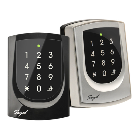
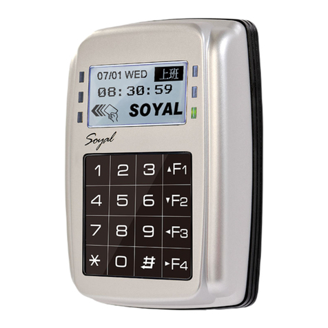
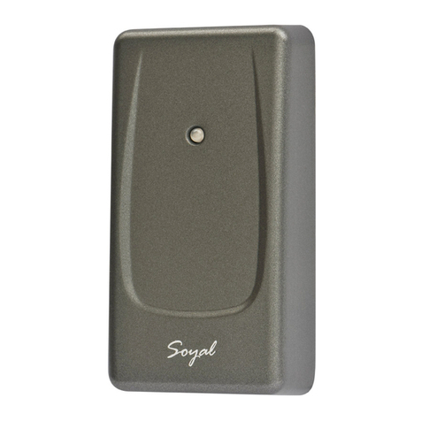
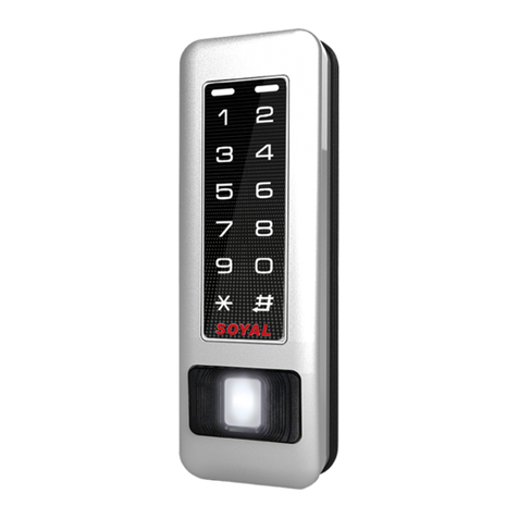
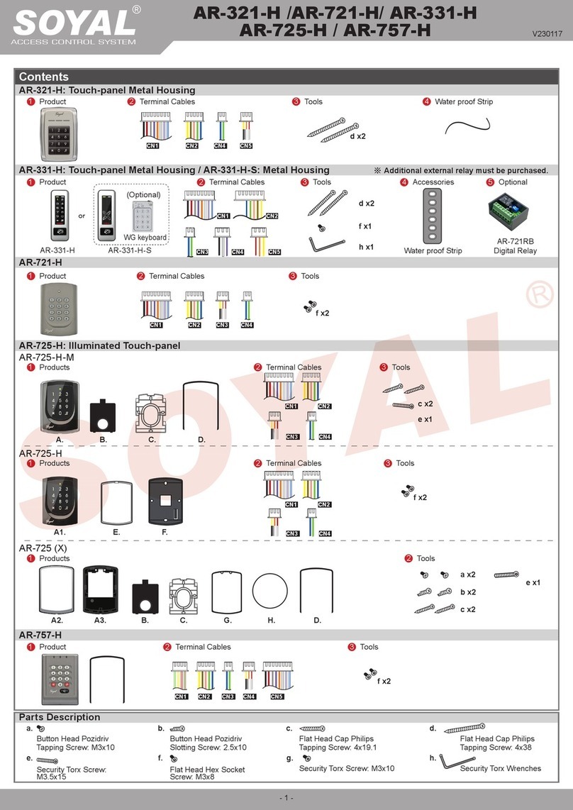
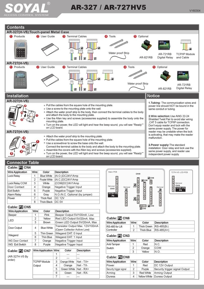
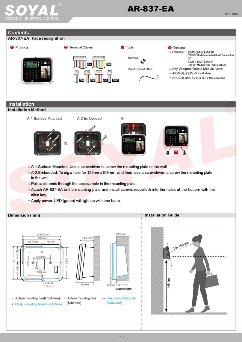
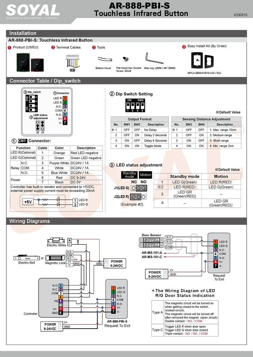
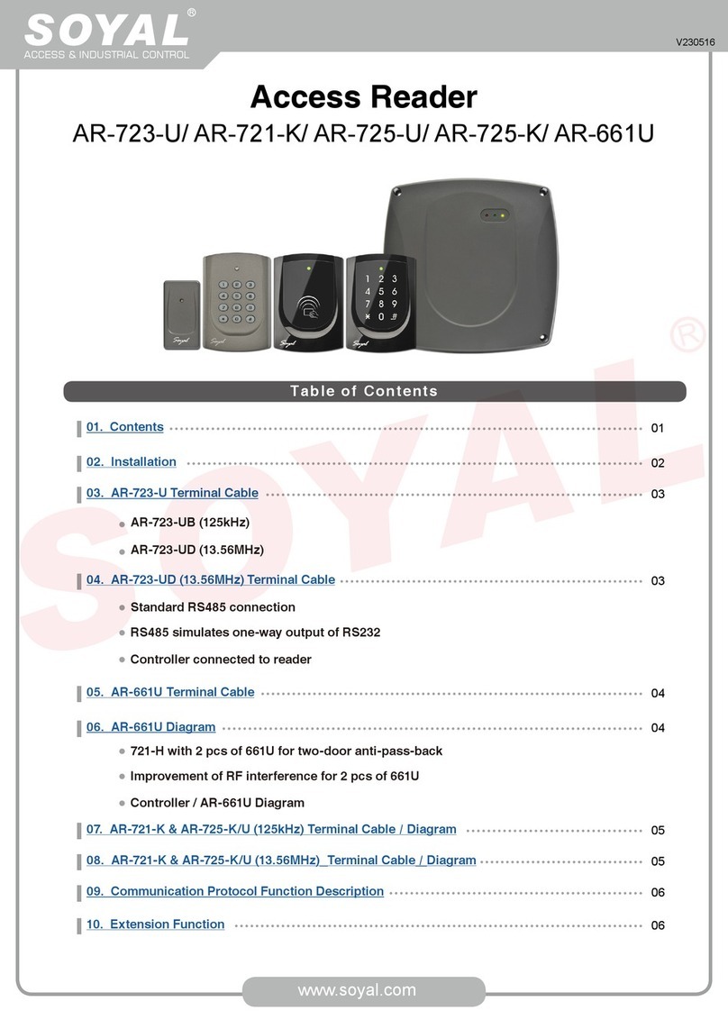
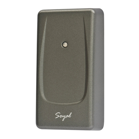
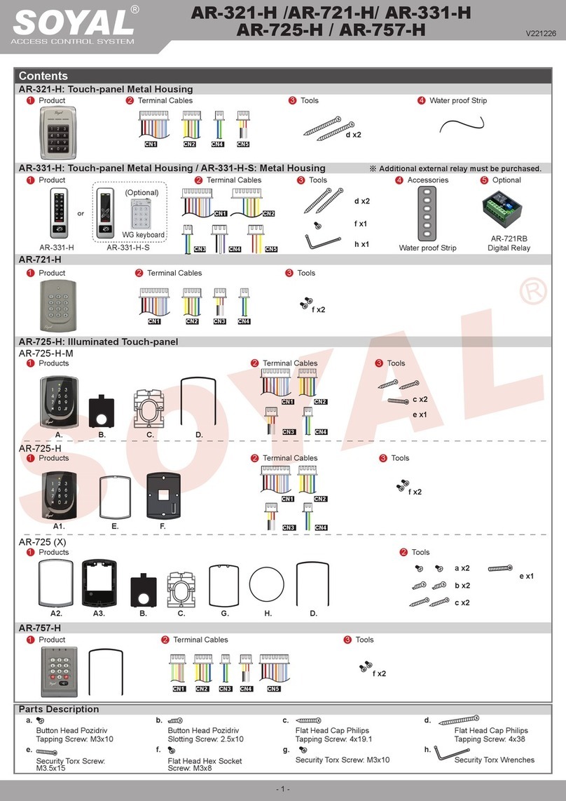
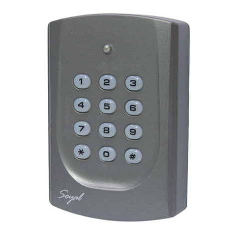
Soyal AR-888H User manual

SOYAL
ACCESS CONTROL SYSTEM
®AR-888 (H/K/U) / PBI-888 V190419
Contents
AR-888(H): Access Controller - LED Ring (Green/Red Only)
AR-888(K/U): Wiegand Reader (K: With Touch Key Panel, U: W/O Touch Key Panel) - LED Ring (Green/Red Only)
AR-PBI888: Capacitive Touch-Less Sensor / Exit Button - LED Ring (Standard: Green/Red ; By Order: Blue/Red)
Product (US/EU)
Product (US/EU)
Product (US/EU)
CN12
Terminal Cables
Terminal Cables
Terminal Cables
(S/N since 1609XXXXXX)
www.soyal.com
Tools
Tools
Tools
Flat Head Hex
Socket Screw:
M3x8
Flat Head Hex
Socket Screw:
M3x8
Flat Head Hex
Socket Screw:
M3x8
Bottom Cover
Bottom Cover
Bottom Cover
Allen key
2MM
48*15MM
Allen key
2MM
48*15MM
Allen key
2MM
48*15MM
X1
X1
X1
X1
X1
X1
CN5
Duress
CN5
Duress
CN4
RS-485
CN2
WG-Input
CN2
WG-Input
CN1 Terminal Connector
NO. 1 2 3 4 5
Printing V G NC COM NO
Function Power Relay Output
Descrption 12VDC V- N.C. COM N.O.
Easy Install Kit
(By Order)
Easy Install Kit
(By Order)
Easy Install Kit
(By Order)
1
1
1
2 3
3
3
2
2
A.
A.
A.
4
4
4
MPLA-888XA18/19 (US / EU)
CN1
CN1
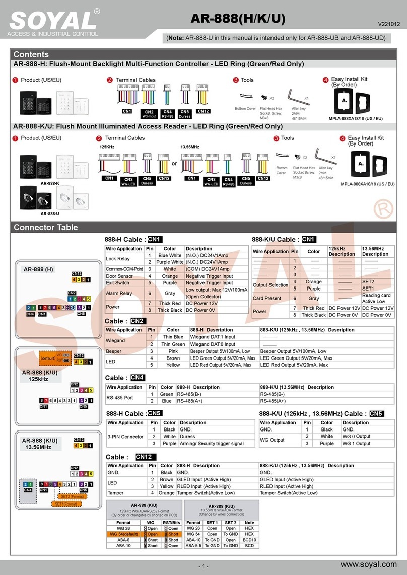
Connector Table
CN12
888H Cable : CN1 888K/U Cable : CN1
Wire Application Pin Color Description
Lock Relay 1 Blue White (N.O.) DC24V1Amp
2 Purple White (N.C.) DC24V1Amp
Common-COM-Point
3 White (COM) DC24V1Amp
Door contact 4 Orange Negative Trigger Input
Exit Switch 5 Purple Negative Trigger Input
Alarm Relay 6 Gray Low output; Max 12V/100mA
(Open Collector)
Power 7 Thick Red DC Power 12V
8 Thick Black DC Power 0V
Wire Application Pin Color Description
1
2
3
Output Selection 4 Orange SET2
5 Purple SET1
Card Present 6 Gray Reading card
Active Low
Power 7 Thick Red DC Power 12V
8 Thick Black DC Power 0V
888H Cable : CN5
Wire Application Pin Color Description
3-PIN Connector
1 Black GND.
2 White Duress
3 Purple Arming/ Security trigger signal
888K/U Cable : CN5
Cable : CN4
Wire Application Pin Color 888H Description 888K/U Description
RS-485 Port 1 Green RS-485(B-) RS-485(B-)
2 Blue RS-485(A+) RS-485(A+)
Cable : CN2
Wire Application Pin Color 888H Description 888K/U Description
Wiegand 1 Thin Blue Wiegand DAT:1 Input
2 Thin Green Wiegand DAT:0 Input
Beeper 3 Pink
Beeper Output 5V/100mA, Low
LED 4 Brown
LED Green Output 5V/20mA, Max
5 Yellow
LED Red Output 5V/20mA, Max
Wire Application Pin Color 888H Description 888K/U Description
GND. 1 Black GND. GND.
LED 2 Brown GLED Input (Active High) GLED Input (Active High)
3 Yellow RLED Input (Active High) RLED Input (Active High)
Tamper 4 Orange Tamper Switch(Active Low) Tamper Switch(Active Low)
Cable : CN12
CN1CN4 CN5
CN2
CN12
AR-888 (K/U)
78
CN1
CN4 CN5
CN2
CN12
AR-888 (H)
Wire Application Pin Color Description
GND. 1 Black GND.
WG Output 2 White WG 0 Output
3 Purple WG 1 Output

V190419
www.soyal.com
Flush-Mounted Series
Access Controller / Wiegand Reader / Infrared Touch-less Sensor (Exit Button)
75
81
84
118
20
15
51
3.3
3.3
24
23
86
88
52
51
13
10
60
18
13
16
12
66
3.3
Cable selection: Use AWG 22-24 Shielded Twist Pair to avoid star wiring.
Use CAT5 for TCP/IP connection.
A.B.C.
D.
2
(Excluded)
By order
5
4
3
3
Installation
Pull the cables from the square holes of the eva foam gasket and mounting plate.
Use a screwdriver to screw the mounting plate B onto the wall with Flat Head Cap Philips Tapping Screws (Excluded, the Installer
should prepare before installation.
Connect the cables to the backside of body Cand attach C to Bat lower position of B. Push Cup to make the cogging hooked completely.
Use the Allen key and screws to assemble the body C onto the mounting plate B. Attach the Back Cover Dto C.
Hands-o and clear any objects around the 888H/K. Turn on the power and LED will light-up and beep will sound. Wait the Touch
IC start for 10 sec. to operate.
(Excluded)
In-wall
Depth
28mm
~35mm
Proportion 1:1
Unit: mm
Proportion 1:1
Unit: mm
Indicators:
AR-888
(H/K/U)
1*Bi-Color Green-Red
3*One Color
LED
Green
(Optional)
White
(Stand-By)
Red
(Optional)
AR-PBI-888 1*Bi-Color Green-Red
(Exchangeable)
US Mounting Hole: 73x48x40mm(HxWxD)
/ Screw hole pitch : 84mm
Suitable for 70X118 1-module ush-
mounting box.( Australian, Italy,
USA(501E) Standard)
EU Mounting Hole: 57x53x40mm(HxWxD)
/ Screw hole pitch: 60mm
Suitable for 86X86 ush-mounting box.
(UK, Continental Europe, Germany
Standard)
1

V190419
29 20
Basic Commands Wiring Diagrams
www.soyal.com
Door Lock Wiring
Door Sensor Wiring
WG Reader Wiring
Networking Connection Wiring
Exit program mode
PIN=0000 (Disable)
PIN=0000 (Disable)
Add PIN User
M4/M8 Mode
13 00001 4321
M6 Mode
17 4321
Add Card+PIN User
Set up Door Relay Time
Set up Door Close Time
TTT: 001~600=1~600 sec.
601~609=0.1~0.9sec.
000=On/ O (Latch)
TTT: 001~600=1~600 sec.
Add Card User
Ex.: 00001 start user address at
00001 and scanned 50 pcs of
card one by one; next time, input
19*00051*00001#
User Range: 00000~03000
(Please list down each User Address
and its Card ID)
M4/M8 Mode
19 00001 00001
M6 Mode
(Must set up 17*0000#)
22 1
Delete Card User
Delete All User Cards
Reset to Factory
Default Value
Ex.:
00001 start user address at 00001
00005 end user address at 00001
Totally 5 user cards will be
disabled.
User Range: 00000~03000
(Delete all cards and parameters)
M4/M8 Mode
10 00001 900005
M6 Mode
10 00001 00005
29 29
Attach/Present Card
One by One
02 007
18 015
M4/M8 Mode (4/8 beeps
while engtering progrm
mode)
12 00001 1234
M6 Mode (6 beeps)
15 1234
Electric Bolt
or
Magnetic Lock
Door Contact
Electric Strike
AR-888 (K/U)
125kHz WG/ABA/RS232 Format
(By order or changable by shorted on PCB)
Format WG RST/Bits
WG 26 Open Open
WG 34(default) Open Short
ABA-8 Short Short
ABA-10 Short Open
AR-888 (K/U)
13.56MHz WG/ABA Format
(Change by wires connection)
Format SET 1 SET 2 Note
WG 26 Open Open HEX
WG 34 Open To GND HEX
ABA-10 To GND Open BCD10
ABA-5-5 To GND To GND BCD
Exit Button Wiring
CN1
Push Button
AR-PBI888
At every 32 units or at every300M
connection to add a RS485 Booster.
Suggest to connect up to 32 units for
each CH of AR-727CM
Notice:
032=Node ID of Access Controller
032=Virtual 716E Node ID
032=Door number
(All Range:001~254)
009=Node ID of Access Controller
Range: 001~254)
Set up Node ID
Ex. Node 32 connected to PC
00 032 032 032
Ex. Node 9 conected to 716E
00 009
Alarm Output 1- Alarm Wiring
Enable Door Open Too Long Alarm
24 064 (Enable)
24 000 (Disable)
Stop Alarm by Push Button
Alarm Output 2- WG Dual Door
Control Wiring
Lock 28 064 (Enable)
28 128 (Disable)
Occupied Alarm Output to support
SET Floor/ Stop
FFFFFFFF
0 87654321
1 16 15 14 13 12 11 10 9
2 24 23 22 21 20 19 18 17
3 32 31 30 29 28 27 26 25
Alarm Output 3-Lift Control Wiring
B-
A+
Host
AR-401RO16B
Node ID 001
Lift
Controller
B-
A+
AR-321L485
Converter
RX
24 002 (Enable)
24 000 (Disable)
Enable Life Control
21 UUUUU SFFFFFFFF
Assign Floor User (Multi-Floor)
S=Set=0~3
FFFFFFFF=0 (Disable) / 1 (Enable)
Ex. Assign user
address 1 to access
to 1, 3, 5, 7 oor
21*00001*0*01010101
#
Assign Users (Single Floor)
27 UUUUU FF
UUUUU=User Address=00000~03000
FF=Floor number=1~32
123456
Enter program mode
Change program code
Input 6-digit PWD twice
POWER
12VDC
External
Relay
Alarm Enable Arming while exit
program mode
Flush-Mounted Series
Access Controller / Wiegand Reader / Infrared Touch-less Sensor (Exit Button)
09 654321654321
AR-888(H)
Node ID
002
AR-888(H)
Node ID
032
AR-888(H)
Node ID
254
B-
A+
B-
A+
B-
A+ Host
CH1
CH2
Each CH up to
8 Nodes Node ID
001
Multi-Door
Controller
Converter
AR-321CM
AR-727CM
DC12V
Card Present
GND
SET1 (WG 格式 )
SET2 (WG 格式 )
CN1
CN1
CN2
CN2
CN5
CN5
CN4
DC12V
DC12V
COM
N.C.
N.O.
GND
GND
AR-888 (H)
RX
1.
GND
2.GLED Input
3. RLED Input
4.
Tamper Switch
GND
GND
Duress
Duress
Arming
Arming
Alarm
PB
Door SEN.
WG0
WG1
Buzzer
GLED
RLED
Buzzer
WG-GLED
RLED
LA+
LB-
CN12
CN12
WG Reader
AR-888 (K/U)
13.56MHz
CN4
LA+
LB-
FW Only
(AR 888-UD)
13.56MHz
SET1(Format)
SET2(Format)
125kHz
WG
RST
Stand-Alone
/Networking
Controller
3. RLED Input
4.
Tamper Switch
2.GLED Input
1.
GND
N.C.
CN1
COM
N.C.
GND
DC12V
N.O.
DC24V/1Amp
N.C.
N.O.
COM
CTL
12V
External
Relay
N.C.
N.O.
COM
CTL
12V
(default)

V190419
www.soyal.com
Flush-Mounted Series
Access Controller / Wiegand Reader / Infrared Touch-less Sensor (Exit Button)
Mode
M4/M6/M8
M4//M6M8
M4/M8
M4/M8
M4/M8
M4/M8
M4/M6/M8
M4/M6/M8
M4/M6/M8
M4/M6/M8
M4/M6/M8
M4/M8
M4/M6/M8
M4/M6/M8
M4/M6/M8
M6
M4/M8
M4/M8
M4/M8
M4/M8
M4/M6/M8
M4/M8
M4/M6/M8
M4/M6/M8
M4/M8
M4/M6/M8
M4/M8
M6
M4/M8
M4/M6/M8
M4/M6/M8
M4/M8
M4/M8
M4/M6/M8
M4/M6/M8
M4/M6/M8
Function
Enter program mode
Exit program mode
Exit program mode and enter arming mode
Node ID setting (Connected to 716E)
Node ID setting (Connected to the PC directly
without 716E)
Mifare tag / card format (Optional)
Door Relay Time setting
Alarm Relay Time setting
Control mode setting
Arming Delay Time setting
Alarm Delay Time setting
Master card (Administrator) setting
Auto-open time zone setting
Master code setting
Suspend / Delete tag
Add a batch of sequential cards by inputting card
number (M6)
Recover the suspended cards
Set the access mode of the user at the designated
User Address as "Card or PIN"
Set the access mode of the user at the designated
User Address as "Card & PIN"
Arming Pulse Time setting
M4/M8:Duress code setting
M6:Public PIN setting for access mode "Card or PIN"
Card number modication
M4/M8:Arming PWD setting
M6:Public PIN setting for access mode "Card & PIN"
Door Close Time
Add card by presenting(M4/M8)
Reader additional setting
Lift control setting: multi-oor
Add/Delete tag by presenting (M6 only)
AR-401RO16 Lift Relay Activated TM
Controller parameter setting
Controller time clock setting
Anti-pass-back (Enable user)
Lift control setting: single oor
Double Door Control / Force Open Alarm
Delete all tags
Enable the security trigger signal
( with AR-721RB)
Description
PPPPPP=Master Code, default value=123456
NNN=Node ID of Access Controller (range: 001~016)
NNN=Node ID of Access Controller (range: 001~254)
VVV=Virtual 716E Node ID, nnn=Door number (range:001~254)
N: 0=ISO14443A; 1=ISO14443B; 2=ISO15693;
3=I Code1; 4=I Code2
PS.1. Please select the transmission standard rst.
2. Ensure both reader and card using the same transmission standard.
TTT=Door relay time 000= Output continuously
001~600=1~600 sec.
601~609=0.1~0.9 sec.
TTT=Alarm relay time 000= Output continuously 001~600=1~600 sec.
N=4: M4; N=6: M6; N=8: M8
TTT=the buer time before entering arming mode 001~600=1~600 sec.
TTT=the buer time before the alarm is activated 001~600=1~600 sec.
SSSSS-EEEEE=00000-01023 (00000-03000 for AR-725H);
SSSSS=Starting User Address; EEEEE=Ending User Address
N= 0 (1st time zone) / 1 (2nd time zone)
HHMM= Starting time; hhmm= ending time
(i.e.: 08301600=08:30 to 16:00)
7123456H= 7 days of week (Sun/Mon/Tue/Wed/Thu/Fri/Sat)+ Holiday
(H= 0: disable; 1: enable); Holidays can be set by 701Client software.
PPPPPP=6-digit new master code
RRRRRR=Reconrm the new master code
=Suspend =Delete;
SSSSS=Starting User Address, EEEEE=Ending User Address
SSSSS=Starting card number
EEEEE=Ending card number
SSSSS=Starting User Address
EEEEE=Ending User Address
Access mode: Card or PIN; UUUUU=User Address;
PPPP=4-digit private PIN (0001~9999); 0000=Card Only for this user
Access mode: Card & PIN; UUUUU=User Address;
PPPP=4-digit private PIN (0000~9999)
TTT=Arming output time; 000=output continuously 001~250=0.1~2.5 sec.
PPPP=4-digit duress code (0001~9999; default value=4321; 0000=disable
the function of simply inputting PIN to get access in M6)
UUUUU= User Address; SSSSS=5-digit site code; CCCCC=5-digit card code
PPPP=4-digit Arming PWD (0001~9999; default value=1234; 0000= access
mode will become "Card Only" in M6)
TTT=Door Close Time: 001~600=1~600 sec.; default value: 15 sec.
UUUUU=User Address; QQQQQ=Card quantity (00001: for adding a single
card or a batch of random numbering cards)
Please refer to function default value for details.
UUUUU=User Address, S=4 sets of lift control (0~3); FFFFFFFF=8 assigned oor
(F=0: Disable, 1: Enable)
N=0(Delete tag); N=1(Add tag)
NNN=site number, TTT= relay time: 000~600=1~600 sec.
Please refer to function default value for details.
YYMMDDHHmmss: Year/ Month/ Day/ Hour/ Min./ Sec.
SSSSS=Starting User Address; EEEEE=Ending User Address;
N=0: Enable; N=1: Disable; N=2: Reset
UUUUU=User Address; FF=Floor (01~32 oor)
Please refer to function default value for details.
Change the "Arming" (in ) to the security trigger signal,
when controller is connected with AR-721RB.
9
CN5
Command
PPPPPP
00 NNN
00 NNN VVV nnn
01 N
02 TTT
03 TTT
04 N
05 TTT
06 TTT
07 SSSSS EEEEE
08 N HHMMhhmm 7123456H
09 PPPPPPRRRRRR
10 SSSSS EEEEE (M6)
10 SSSSS EEEEE (M4/M8)
11 SSSSS EEEEE
11 SSSSS EEEEE
12 UUUUU PPPP
13 UUUUU PPPP
14 TTT
15 PPPP
16 UUUUU SSSSSCCCCC
17 PPPP
18 TTT
19 UUUUU QQQQQ
20 DDD
21 UUUUU S FFFFFFFF
22 N
23 NNN TTT
24 DDD
25 YYMMDDHHmmss
26 SSSSS EEEEE N
27 UUUUU FF
28 DDD
29 29
34 128 (321H/721H/725H/757H/888H)
34 064 (723H/331H)
34 000 (Disable)
9
Command List
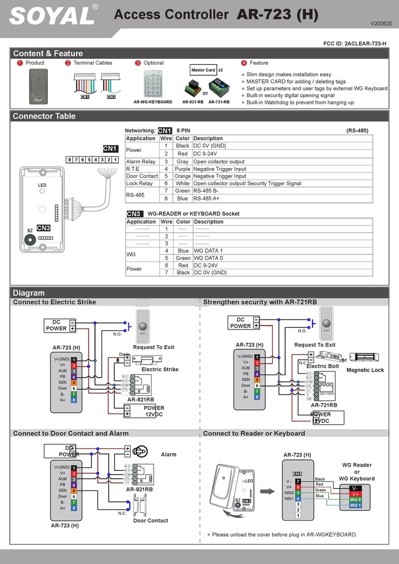
Other manuals for AR-888H
1
This manual suits for next models
4
Other Soyal IP Access Controllers manuals

Soyal
Soyal AR-829E User manual

Soyal
Soyal AR-725E User manual

Soyal
Soyal AR-723-H User manual

Soyal
Soyal AR-363-E User manual

Soyal
Soyal AR-331-E User manual

Soyal
Soyal AR-881-EF9DO User manual

Soyal
Soyal AR-327-E User manual

Soyal
Soyal AR-721K User manual

Soyal
Soyal AR-725E User manual

Soyal
Soyal AR-327-E User manual

Soyal
Soyal AR-723 User manual

Soyal
Soyal AR-721U User manual

Soyal
Soyal AR-837-E User manual

Soyal
Soyal AR-327 User manual

Soyal
Soyal AR-837-E User manual

Soyal
Soyal AR-888-PBI-S User manual

Soyal
Soyal AR-837 E User manual

Soyal
Soyal AR-327-E User manual

Soyal
Soyal AR-727iV3 User manual

Soyal
Soyal AR-888-PBI User manual