Euro Systems Carry Series User manual

Istruzioni d’uso
Operating instructions
Bedienungsanleitung
Mode d’emploi
Instrucciones para la utilización
MOTOCARRIOLA
WHEELBARROW
MOTORSCHUBKARRE
MOTOBROUETTE
CARRETILLA MOTORIZADA


1
3 4
2

5 6
7

8

Leggere il manuale prima di usare la
macchina.
Read the instructions manual before
operating on the machine.
Lesen Sie die
Gebrauchsanweisung vor der
Inbetriebnahme.
Lire le mode d'emploi avant l'usage.
Leer el manual antes de usar la
máquina.
Etichetta schema bloccaggio/sbloccaggio ruote.
Label scheme for wheels block/unblock.
Aufkleber mit Schema zur Ver-/Entriegelung der Räder.
Étiquette schéma de blocage/déblocage des roues.
Etiqueta esquema bloqueo/desbloqueo ruedas.
Etichetta carico massimo e pendenza massima consentita.
Label showing the maximum permissible load and maximum
allowed slope.
Bitte beachten Sie die zulässige Maximalbelastung, sowie die
höchstzugelassene Steigung wie auf dem Aufkleber beschrieben.
Etiquette de charge limite et de la pente maximale permise.
Etiqueta carga máxima y pendiente máxima permitida.
Etichetta istruzioni per sollevamento vasca.
Label instructions for tank overturning.
Hinweis gemäß Aufkleber für die Entleerung der Wanne.
Etiquette d’instructions pour l’élévation maximum du bac.
Placa instrucciones para elevación contenedor .

Etichetta innesto marcia avanti.
Label: forward gear clutch.
Aufkleber zum Einschalten der
Vorwärtsgänge.
Étiquette introduction de la marche avant.
Etiqueta conexión marcha adelante.
Etichetta innesto retro marcia.
Label instruction for reverse gear
clutch.
Aufkleber für
Rückwärtsgangeinschaltung.
Étiquette introduction de la marche
arrière.
Etiqueta conexión marcha atrás.

INDICE
Introduzione
Condizioni di utilizzo
Norme di sicurezza
Dispositivo di sicurezza
Montaggio
Regolazioni
Descrizione comandi
Istruzioni d’uso
Rimessaggio
e manutenzione periodica
Rumore aereo
Dati Tecnici
Accessori
INTRODUZIONE
Gentile Cliente, la ringraziamo per la fiducia accordata al nostro prodotto, le auguriamo un piacevole e sicuro
utilizzo di questa macchina.
Questo libretto contiene tutte le informazioni per un uso corretto e senza problemi, perciò si consiglia di leggere
attentamente le NORME DI SICUREZZA e le ISTRUZIONI D’USO qui di seguito riportate, per avere un funzio-
namento senza inconvenienti e una durata sicura, della macchina, nel tempo.
Per garantire questo, è necessario utilizzare esclusivamente ricambi originali.
L’utilizzatore perde ogni diritto di garanzia qualora vengano utilizzati ricambi non originali.
Con riserva di variazioni tecnico-costruttive.
Per informazioni e per ordinazioni di pezzi di ricambio si prega citare il numero dell’articolo relativo, nelle
eventuali richieste di Assistenza Tecnica o nelle ordinazioni delle Parti di Ricambio citare sempre il
numero di matricola della macchina interessata, rilevando i dati dall’etichetta di identificazione posta
sul fianco sinistro della macchina. (Fig.1)
CONDIZIONI DI UTILIZZAZIONE – LIMITI D’USO
La motocarriola è progettata e costruita per eseguire operazioni di trasporto di oggetti e materiali inerti. Ogni
utilizzo diverso da quello sopra descritto è illegale; comporta, oltre al decadimento della garanzia, anche un
grave pericolo per l’operatore e le persone esposte.
NORME DI SICUREZZA
Sulla macchina ed all’interno di questo libretto sono presenti scritte ed indicazioni accompagnate
da questo segnale, che stanno ad indicare la presenza di un potenziale pericolo. E' opportuno
utilizzare una particolare prudenza per la propria sicurezza e di quanti si possono trovare nel
raggio di azione della macchina.
ATTENZIONE: prima del montaggio e la messa in funzione leggere attentamente il libretto istruzione. Le
persone che non conoscono le norme di utilizzazione non possono usare la macchina.
1 Impedire l’uso ai minori di 16 anni.
2 Controllare che i bambini stiano lontani. Siete responsabili dei danni causati a terzi.
3 Avviare il motore rimanendo dietro il manubrio di guida.
4 Durante il trasporto della macchina e tutte le operazioni di manutenzione, pulitura, cambio degli attrezzi,
il motore deve essere spento.
5 Allontanarsi dalla macchina non prima di aver spento il motore. Non lasciare la macchina incustodita.
6 Non avviare la macchina in locali chiusi dove si possono accumulare esalazioni di carbonio.
7 AVVERTENZA La benzina è altamente infiammabile:
- Non fare il pieno di benzina in locali chiusi né con il motore in moto, non fumare e fare attenzione alle 1
ITALIANO

fuoriuscite di combustibile dal serbatoio.
- In caso di fuoriuscita non tentare di avviare il motore, ma allontanare la macchina dall’area interessata evitando di creare fonti di accensione
finché non si sono dissipati i vapori della benzina
- Rimettere a posto correttamente i tappi del serbatoio e del contenitore della benzina.
8Attenzione al tubo di scarico. Le parti vicine possono arrivare a 80° centigradi. Sostituire i silenziatori usurati o difettosi.
9 Non usare la motocarriola su pendenze superiori ai 35°, potrebbe ribaltarsi. Sui pendii lavorare sempre in salita o discesa e non trasversal-
mente, porre sempre la massima cautela nei cambi di direzione.
10 Non caricare pesi superiori a quelli riportati sull’etichetta posta all’interno della vasca od oggetti che sporgano in altezza oltre la visibilità del
conducente ed in larghezza oltre le dimensioni della vasca, poiché questo potrebbe compromettere la stabilità e la guidabilità della motocarriola.
11 Sganciare la vasca, per il rovesciamento, rimanendo esclusivamente dalla parte del manubrio. Fare attenzione alla natura del carico, se è
ghiacciato o appiccicoso ci sono rischi di ribaltamento.
12 Prima di iniziare il lavoro con la macchina procedere ad un controllo visivo del serraggio di tutti i componenti, dell’integrità macchina e della
pressione dei pneumatici, quindi verificare che tutti i sistemi antinfortunistici, di cui essa è dotata, siano perfettamente funzionanti. E’ severa-
mente vietato escluderli o manometterli.
13 Ogni utilizzo improprio, le riparazioni effettuate da personale non specializzato o l’impiego di ricambi non originali, comportano il decadimen-
to della garanzia e il declino di ogni responsabilità della ditta costruttrice.
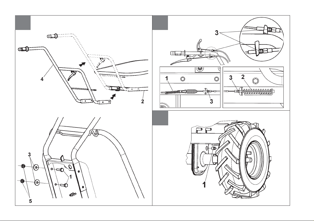
DISPOSITIVO DI SICUREZZA
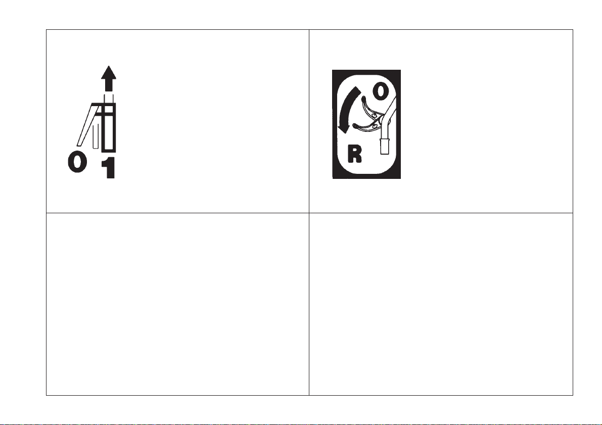
Tutte le motocarriole sono dotate di dispositivo antinfortunistico. Detto dispositivo causa il disinnesto della frizione e di conseguenza l’arresto della
macchina in marcia avanti o a marcia indietro, al rilascio della relativa leva di comando; inoltre questo dispositivo evita l’inserimento della retromarcia
mentre è inserita la marcia avanti.
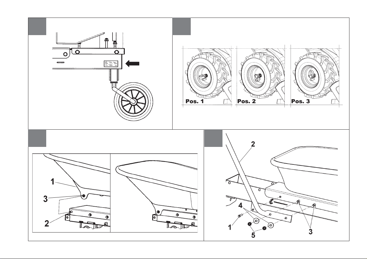
Dispositivo innesto ruote a tre posizioni: (Fig.2) La motocarriola è dotata di uno speciale dispositivo chiamato “FORCELLA A TRE POSIZIONI”.
Nella posizione 1(libero) la ruota gira libera sull’albero così da permettere gli spostamenti della macchina a motore fermo.
Nella posizione 2(bloccato) la ruota risulta solidale con l’albero, diventando motrice, cioè pronta per il lavoro, normalmente la più usata. Questa
posizione è obbligatoria quando si usa la motocarriola su piani in pendenza.
Nella posizione 3(semidifferenziale) la ruota ha la possibilità di fare circa un giro libera sull’albero, così da permettere inversioni di marcia.
ATTENZIONE Tutti gli interventi sulla forcella a tre posizioni, devono essere eseguiti a motore spento e su una superficie piana.
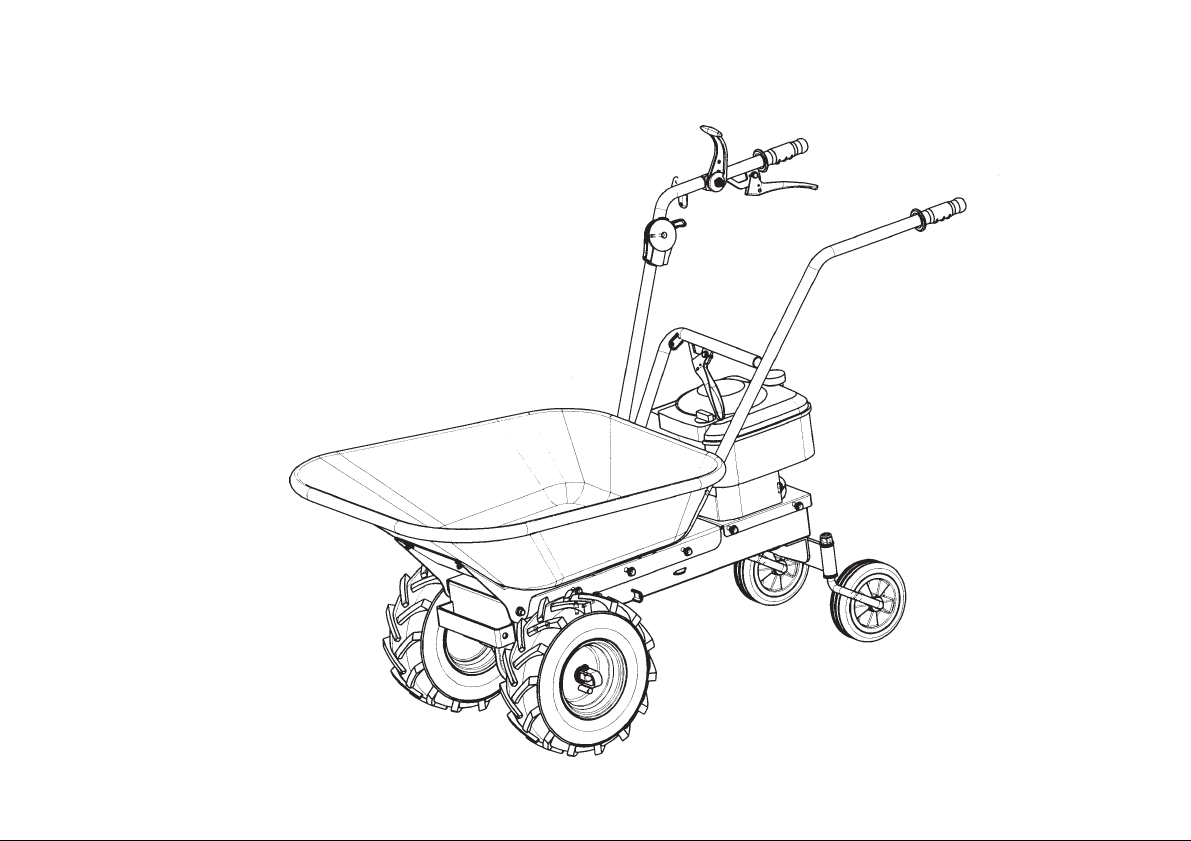
MONTAGGIO DELLA MOTOCARRIOLA
La motocarriola viene consegnato a destinazione, salvo accordi diversi, parzialmente smontata e sistemata nel suo imballo. Per rendere la motocarriola
funzionante bisogna completare il montaggio delle parti smontate osservando la seguente procedura.
MONTAGGIO PIASTRA RIBALTABILE CON VASCA (Fig. 3)
Prelevare la piastra e la vasca già assemblati fra loro (part.1) dall’imballo, sovrapporre il tutto alla macchina in prossimità dei perni di sbloccaggio (2),
ed esercitando una pressione su di essi (non contemporaneamente) bloccare la piastra ribaltamento facendo passare i perni (2) attraverso i fori (3)
presenti sulla piastra.
2
ITALIANO

MONTAGGIO MANUBRIO DESTRO (Fig. 4)
Smontare la vite (1) dalla macchina, fissare il manubrio destro (2) direttamente al corpo della macchina in prossimità delle viti saldate (3) per mezzo
delle rondelle (4) e dadi (5) e riavvitare la vite (1) dopo aver inserito il manubrio.
MONTAGGIO MANUBRIO SINISTRO (Fig. 5)
Fissare il manubrio sinistro (4) alla piastra ribaltamento (2) negli appositi fori per mezzo delle viti (1), delle rondelle (3) e dei dadi (5); abbassare il tutto
in modo tale che la piastra ribaltamento ed il manubrio sinistro risultino agganciati alla macchina (part.2).
REGOLAZIONI (Fig. 6) Registrazione del tendicinghia comando marcia avanti e marcia indietro:
Attenzione, le ruote devono iniziare a girare solo quando la leva di comando ha superato la metà della propria corsa. Quando la leva è completa-
mente tirata (posizione di lavoro), la molla di carico del tendicinghia (part.1 marcia avanti) e (2 marcia indietro) si deve allungare di circa 6-8 mm. Per
ottenere le condizioni sopracitate, occorre agire sul registro (3) installato nelle vicinanze delle relative leve di comando.
DESCRIZIONE COMANDI (Fig. 8)
1) Leva comando acceleratore Start-Stop 2) Leva comando marcia avanti 3) Leva comando marcia indietro 4) Leva comando sgancio vasca per
ribaltamento. 5) “Forcella a tre posizioni” 6) Maniglia di avviamento motore.
ISTRUZIONI D’USO Dopo le operazioni di montaggio e regolazione la motocarriola è pronta per lavorare.
ATTENZIONE Prima di avviare il motore controllare sempre che la motocarriola sia in perfette condizioni di funzionamento.
- Istruzioni Motore: Leggere attentamente il libretto istruzioni allegato del relativo motore.
-Controllare che il filtro aria sia ben pulito.
-Riempire il serbatoio di carburante del tipo indicato dalle specifiche nel libretto del motore usando un imbuto con filtro.
-Non modificare la taratura del regolatore di velocità di rotazione del motore e non far raggiungere ad esso una condizione di sopravvelocità.
-Posizionare la forcella (Fig.2) nella posizione 1(libero) la ruota gira libera sull’albero così da permettere gli spostamenti.
- Posizionare la forcella (Fig.2) nella posizione 2 (bloccata) posizione di lavoro.
- Messa in moto del motore: Aprire il rubinetto del carburante (per i motori provvisti), spingere fino a metà la levetta dell’acceleratore posto sul
manubrio (Fig.8 part.1) se il motore è freddo, azionare il dispositivo di starter sul carburatore, afferrare la maniglia di avviamento e dare uno
strappo energico.
- Avviato il motore riportare, dopo i primi scoppi, lo starter nella posizione di riposo.
-Impugnare il manubrio, inserire la marcia agendo su apposita leva.
-Tirare la leva frizione part.2 (Fig.8) per tutta la sua corsa.
- Marcia indietro: lasciare la leva frizione part.2 (Fig. 8) e tirare verso di sè la leva posta sul manubrio part. 3 (Fig. 8) fino a che la macchina
non cominci ad indietreggiare. Porre particolare attenzione alle condizioni del terreno ed agli eventuali ostacoli presenti.
- Ribaltamento vasca: La motocarriola è provvista di una leva part. 4 (Fig.8) per lo sgancio della vasca, in modo da permettere il rovesciamento
del contenuto, questa si aggancia automaticamente quando si riporta la vasca in piano. Controllare il corretto aggancio.
- Fine lavoro: Terminato il lavoro, per arrestare il motore, portare la leva acceleratore nella posizione di minimo o azionare l’interruttore di stop sul
motore.
3
ITALIANO

RIMESSAGGIO E MANUTENZIONE PERIODICA Mantenere serrati tutti i dadi, i bulloni e le viti per garantire il funzionamento della
macchina nelle condizioni di sicurezza. Lasciar raffreddare la macchina prima di immagazzinarla e comunque non riporla con benzina nel serbatoio
all’interno di un edificio, dove i vapori possono raggiungere una fiamma libera od una scintilla. Per ridurre il pericolo di incendio mantenere il motore,
il silenziatore e la zona di immagazzinamento della benzina liberi da foglie, erba e grasso in eccesso.
Eseguire le operazioni sottoelencate agli intervalli prescritti (per “ore” si intendono le ore di lavoro della macchina).
Scatola cambio (Fig. 7)
Controllo livello olio: Lubrificante: usare olio SAE 80. Verificare il livello dell’olio ogni 60 ore: mettere la macchina in piano, svitare il tappo (1) e
controllare che l’olio sia al margine inferiore del foro, nel caso sia necessario il ripristino del livello rabboccare dallo stesso foro, fino a che l’olio non
cominci ad uscire. Riavvitare il tappo.
Cambio olio: Sostituire l’olio ogni 150 ore. Lo scarico dell’olio deve essere effettuato a macchina calda: svitare il tappo (1), inclinare la macchina per
svuotarla completamente, quindi, rifornirla di olio dallo stesso foro (1), fino che l’olio non cominci ad uscire. Riavvitare il tappo.
Attenzione: L’olio di scarico è un materiale inquinante non disperdere nell’ambiente, ma servirsi degli appositi centri di raccolta.
RUMORE AEREO E VIBRAZIONI
Valore di pressione acustica al posto di lavoro secondo la Dir. 98/37/CE LA e q = 84,6 dB (A). Vibrazione alle stegole secondo EN 1033 e ISO 5349.
Valore massimo rilevato = 3,9 m/s². Valore di potenza acustica secondo la EN ISO 3744 LWA = 97,2 dB (A).
DATI TECNICI
Lunghezza massima
Larghezza massima
Altezza massima
Massa
Larghezza esterna ruote
Velocità marcia avanti
Velocità retromarcia
Carico massimo trasportabile in piano
Volume massimo
1435 mm
705 mm
910 mm
56 kg
570 mm
3,6 km/h
2,0 km/h
100 kg
85 Lt.
Per i dati tecnici relativi al motore, vedere l’allegato manuale di istruzioni.
ACCESSORI
Lama da neve frontale con maniglia di regolazione - Coppia catene da neve per ruote pneumatiche - Piattaforma in lamiera cm. 59x81 completa di
contenitore in materiale plastico.
4
ITALIANO

INDEX
Introduction
Conditions of use
Safety norms
Safety device
Assembly
Adjustments
Control system
Operating Instructions
Garaging & scheduled
maintenance
Noise level
Technical details
Accessories
INTRODUCTION
Dear Customer,
thank you for the confidence in purchasing our product .We hope you will spend many enjoyable hours using it.
The present instructions are issued to ensure a right and correct use of the product : for this reason we beg
you to carefully follow such working and safety instructions so that the machine could operate with complete
satisfaction and have a long service life.
To guarantee what above it is necessary to fit the machine with original components/spare parts.
The user/operator forfeits any claims which may arise if the machine is fitted with components other
than original spare parts.
Subject to changes in design and construction without notice.
In order to process customers’ technical information and spare parts orders, please always state the
machine serial number you can see printed on the label placed on the machine left side (Fig. 1).
CONDITIONS AND LIMITATIONS OF USE
The wheelbarrow is designed and built to transfer items and inert substances. The wheelbarrow must only be
used with original equipment and spares. Any use other than those here described is prohibited and will
involve, in addition to cancellation of the warranty, serious risk for the operator and bystanders.
SAFETY PRECAUTIONS & ACCIDENT PREVENTION MEASURES.
Both on the machine body and in the present instructions booklet can be found indications and
notices linked to the a.m. symbol: in such cases please be careful because you can face potential
danger so it is recommended to use a special caution both for operator’s own sake and
bystanders’.
WARNING! Before assembly and putting the machine into operation , please read carefully the operating
instructions. Persons not familiar with such instructions are not authorized to use the machine.
1 Persons under 16 should not be allowed to use the machine.
2 When operating the machine, the user should ensure that no others, particularly children, are
standing in the area. Please, remember that you are responsible for the safe operating of your machine
vis-a-vis third persons.
3 Start the engine standing behind the handlebars.
4 During the machine transport and all the maintenance, cleaning, equipment change operations, the
engine must be switched off.
5 Before leaving the machine, please switch the engine off.
6 Do not switch the machine on in closed rooms/areas where you can have carbon monoxide exhalations.
7 WARNING !! The petrol/gasoline is highly inflammable: Don’t fill the tank neither in closed areas, nor 5
ENGLISH

when engine is on, don’t smoke and be careful to the petrol/gasoline loss from the tank. In case of leak, don’t try to switch the engine on but
move the machine away from the area in order to avoid ignition source until the gasoline vapours fade away. Re-place the tank caps and the
gasoline box.
8Keep attention to the exhaust pipe. The parts near the pipe can reach 80°C. Replace the defective and/or worn out silencers.
Burn hazards !!!
9Do not use the wheelbarrow on slopes higher than 35°, as it could overturn. If you are working on slopes, go up/go down straightly, avoid to
drive the unit crosswise. Be careful when you change your direction.
10 Do not load the wheelbarrow with higher weights than the ones shown on the label sticked on the internal tank side, neither fill with objects
overhanging the driver sight nor objects extending beyond the tank dimensions: such behaviour could compromise the wheelbarrow stability
and guidability.
11 When you overturn the tank, we recommend you to stay exclusively on the handlebar side. Please, be careful about the kind of loading
with your unit: if the contents are iced or sticky you risk to overturn the wheelbarrow.
12 Before putting the machine into operations, check it visually and make sure all the accident prevention measures are working. It is
absolutely forbidden to exclude and/or to tamper with them.
13 In case the machine is incorrectly used, and/or the repairs are performed by non-authorized technical staff, and/or fitted by non-original
spare parts: any use other than that described above is prohibited and will involve the cancellation of the warranty and the refuse all
responsability from the manufacturer.
SAFETY DEVICE
All the wheelbarrows are equipped with an accident prevention device. Such device causes the clutch release and the machine stopping on the single
or reverse speed position, to the release of the control lever, furthermore such device avoids the reverse speed insertion if the single speed is on.
Wheels insertion device on 3 positions : (Fig.2)
The wheelbarrow is provided with a special device called “FORK 3 POSITIONS”
On position 1(free) the wheel turns free on the shaft in order to let the machine to move even if the engine is not working;
On position 2(blocked) the wheel is working with the shaft, working as on motion, i.e. ready to start working, such position is the most common used;
On position 3(semi-differential unit) the wheel can perform about a half-turn turning on the shaft, in order to allow turns.
WARNING ! All the works on the fork must be performed when the engine is stopping .
WHEELBARROW ASSEMBLY
The wheelbarrow is delivered to destination, partially assembled in its own packaging, unless otherwise agreed.
TO ASSEMBLE THE OVERTURNING PLATE WITH THE TANK (FIG. 3)
Take the plate and the tank (you can find them assembled part. 1 in the packaging), lay them on the unit close to the unblock pins (2) and press on
them (not at the same time), lock the overturning plate making the pins (2) to pass through the plate holes (3).
RIGHT HAND HANDLEBAR ASSEMBLY (FIG. 4)
6
ENGLISH

Unscrew the screws (1) from the unit, fix the right –hand handlebar (2) directly to the chassis next to the welded screws (3) using the enclosed
washers (4) and nuts (5). Then screw again (1) after inserting the handlebar.
LEFT SIDE –HAND HANDLEBAR (FIG. 5)
Fix the left-hand handlebar (4) to the overturning plate (2) into the holes using the enclosed screws (1), the washers (3) and the nuts (5): lower the
whole in order to make the overturning plate and the left handlebar to couple the unit (part. 2).
ADJUSTMENTS (Fig.6)
Adjustment of the belt stretcher driving wire single speed and reverse: Attention, the wheels have to start working only when the control lever
has moved halfway its travel. When the lever is completely pulled (working position), the spring load of the belt stretcher (part. 1 single speed) and
(part.2 reverse speed) must extend for 6-8 mm. In order to obtain he a.m. conditions you have to act on the regulator (3) you can see near the drive
control lever.
CONTROLS DESCRIPTION (Fig.8)
1) Accelerator lever control Start-Stop 2) Forward speed lever control. 3) Reverse speed lever control. 4) Drive control lever for the tank overturning.
5) “Fork on 3 positions” 6) Starter handle.
INSTRUCTIONS
Following the assembly & adjustment operations the wheelbarrow is ready to start working.
ATTENTION ! Before switching the engine on, carefully check if the wheelbarrow is in perfect good conditions.
-Engine instructions: Carefully read the istructions booklet anclosed to the relevant engine.
-Check if the air filter is clean.
-Fill the tank in as per the fuel described in the engine specifications and using a filter filling funnel.
-Do not change the calibration of the speeds control rotation device of the engine in order not to over-speed it.
-Put the fork (Fig.2) into position 1 (free) so that the wheel could freely turn on the shaft to allow the movements.
-Put the fork (Fig.2) into position 2 (block) working position.
- How to switch the engine on (Fig.8): Open the fuel cap (for the engine equipped like this), push to halway the accelerator lever on the
handlebar (part.1) if the engine is cold, operate the starter device on the carburetor, bring the starter handle and pull energetically.
When the engine is on, after some bursts/bangs, put the starter again at rest position.
-Pull the clutch lever (part.2) to the end of its way.
-Reverse speed: release the clutch lever (Fig.8) (part.2) and pull towards ourselves the lever on the handlebar (3) until the machines starts to
draw back. Please, take care to the ground conditions and about any obstacles you may face.
-Tank overturning: the wheelsbarrow is equipped of a lever (part.4 fig. 8) for the tank overturning in order to allow you empty the contents. Such
lever automatically hooks when the tank comes back to a flat surface.
-At the end of the work: when you finish the work, to stop the engine, bring the accelerator lever to the bottom gear or press the stop switcher
on the engine. 7
ENGLISH

GARAGING AND SCHEDULED MAINTENANCE
Keep attention that all the nuts, screws and bolts are tightened in order to guarantee a good machine working on safety conditions. Leave the machine
to cool before garaging anyhow don’t room it if the tank still contains some fuel as the vapours could reach some blazes or sparks. To lower the fire
danger, keep the engine, the silencer and the fuel area free from leaves, grass or greasy substances.
Perform the following operations as per the described intervals. (with the word “Hours”, we mean the machine working hours).
Gearbox (Fig. 7)
Oil level control: Use oil SAE 80. Verify the oil level every 60 hours: put the machine on flat surface, remove the cap (1) and check if the oil reaches
the hole bottom edge. In case you need to fill it on you have to perform it from the same hole. Go on with such operation until you see the oil coming
out. Screw both cap again.
Oil change: change the oil every 150 hours. The oil drain has to be performed when the machine is hot: remove cap (1) and tilt the machine to a
complete emptying, then put the machine on flat land, fill it in with oil through the hole until the oil starts coming out from it. Screw both cap again.
ATTENTION ! Waste fuel oil is a polluting material: don’t waste it in the sorroundings, please apply to suitable waste material centres.
NOISE LEVEL AND VIBRATION LEVEL
Acoustic pression value (working place) accordino to the Directive 98/37/CE LA e q = 84,6 dB (A). Handlebars vibrations accordino to EN 1033 and
ISO 5349. Maximum measured value = 3,9 m/s². Acoustic power value according to EN ISO 3744 LWA = 97,2 dB (A).
TECHNICAL DETAILS
Maximum lenght
Maximum width
Maximum high
Mass
External wheels width
Forward speed
Reverse speed
Maximum load on a flat surface
Maximum volume
1435 mm
705 mm
910 mm
56 kg
570 mm
3,6 km/h
2,0 km/h
100 kg
85 Lt.
As far as concerns the engine technical specifications, please see the enclosed instructions booklet.
ACCESSORIES
Front snow blade with adjustable handle - Snow chains pair for pneumatic wheels - Sheet platform cm. 59x81 equipped with plastic collector.
8
ENGLISH

Inhaltsverzeichnis
Einleitung
Einsatzbedingungen
Sicherheitsbestimmungen
Sicherheitsvorrichtung
Montage
Einstellungen
Beschreibung der
Bedienelemente
Betriebsanleitung
Lagerhaltung und laufende
Wartung
Lärmpegel
Technische Daten
Zubehöre
EINLEITUNG
Sehr geehrter Kunde, wir danken Ihnen für das Vertrauen, das Sie unserem Produkt geschenkt haben. Wir
wünschen Ihnen eine angenehme und sichere Benutzung dieser Maschine. Dieses Handbuch enthält alle
Informationen für einen korrekten und problemlosen Gebrauch. Daher empfehlen wir Ihnen, die auf den folgenden
Seiten stehenden SICHERHEITSBESTIMMUNGEN und GEBRAUCHSANLEITUNGEN aufmerksam zu lesen,
damit Sie die Maschine auf lange Zeit störungsfrei und sicher benutzen können.
Um dies zu gewährleisten, ist es erforderlich, ausschließlich Originalersatzteile zu verwenden. Der
Anwender verliert jeden Anspruch auf Garantie, wenn er Ersatzteile verwendet, die kein Original sind.
Konstruktionsänderungen sind vorbehalten. Für Informationen und zum Bestellen von Ersatzteilen geben Sie
bitte immer die Artikel-Nr. an, bei den etwaigen Anforderungen des Kundendienstes oder beim Bestellen
von Ersatzteilen ist immer die Seriennummer der fraglichen Maschine anzugeben, wobei diese Daten
auf dem Typenschild abzulesen sind, das sich auf der linken Seite der Maschine befindet. (Abb. 1)
EINSATZBEDINGUNGEN - EINSATZGRENZEN Der Einachsschlepper ist zur Ausführung von
Hackarbeit. Der Einachsschlepper darf nur mit Original-Zusatzgeräten und Original-Ersatzteilen arbeiten. Jede
Benutzung, die von der hier beschriebenen abweicht, ist nicht gestattet. Es führt nicht nur zum Verfall der
Garantiegewährung, sondern stellt auch eine große Gefahr für den Bediener und alle Personen die sich in
Reichweite der Maschine befinden dar.
SICHERHEITS- UND UNFALLVERHÜTUNGSBESTIMMUNGEN
Auf der Maschine und in diesem Handbuch stehen einige Meldungen und Angaben, die von diesem
Signal begleitet werden. Sie geben das Vorhandensein einer potentiellen Gefahr an, so dass es
angemessen ist, der eigenen Sicherheit und der Sicherheit derer wegen, die sich in der Reichweite der
Maschine befinden könnten, eine besondere Vorsicht walten zu lassen.
Achtung: Vor der Montage und der Inbetriebnahme unbedingt die Betriebsanleitung aufmerksam
durchlesen. Personen, welche die Bestimmungen zur Benutzung nicht kennen, dürfen die Maschine
nicht verwenden.
1 Jugendlichen unter 16 Jahren ist der Gebrauch zu verbieten.
2 Sicherstellen, dass keine Kinder in der Nähe sind. Sie sind für die Schäden verantwortlich, die Dritten
entstehen.
3 Achten Sie darauf, daß Sie beim anwerfen des Motores hinter dem Gerät bzw. dem Holmen stehen.
4 Während des Transports der Maschine und aller Wartungsarbeiten, dem Reinigen und dem Wechsel
der Geräte muss der Motor immer abgeschaltet sein.
5 Entfernen Sie sich erst dann von der Maschine, wenn man den Motor abgeschaltet hat.
6 Die Maschine nicht in geschlossenen Räumen laufen lassen, wo die entstehenden Abgase sich
anhäufen könnten.
7 HINWEIS Benzin ist ein feuergefährlicher Stoff: Nicht in geschlossenen Räumen und nicht bei laufendem 9
DEUTSCH

Motor tanken, nicht rauchen und auf den aus dem Tank auslaufenden Treibstoff achten. Bei auslaufendem Treibstoff nicht versuchen, den
Motor zu starten, sondern die Maschine von der betroffenen Stelle entfernen und vermeiden, Zündquellen zu erzeugen, bis die Benzindämpfe
nicht abgezogen sind. Die Stopfen des Tanks und des Benzinbehälters wieder ordentlich aufschrauben.
8Auf das Auspuffrohr achten. Die nahe am Auspuff liegenden Teile können bis zu 80° heiß werden. Verschlissene oder defekte Auspufftöpfe
ersetzen.
9 Die Motorschubkarre sollte an Steigungen oder Gefällen, die größer als 35° sind nicht verwendet werden - die Gefahr, daß sich die
Motorschubkarre überschlägt ist zu hoch.An Hängen sollte nicht quer gearbeitet werden, sondern immer bergauf/bergab. Richtungsänderungen
bzw. das Umdrehen sollte immer sorgfältig durchgeführt werden.
10 Der Aufkleber im Wanneninneren mit den Maximalwerten sollte beachtet werden. Bitte die maximale Traglast nicht überschreiten. Die zu
transportierenden Gegenstände dürfen den Lenker in seinem Sichtfeld und seiner Sichtweite nicht behindern. Auch sollten die zu
transportierenden Gegenstände nicht breiter als die Wanne sein.
11 Um die Wanne zu Entleeren muß der Betätigunshebel am Holmen entriegelt werden. Somit kann der Kippvorgang beginnen. Zur
Unterstützung des Kippvorgangs dient der entriegelte Holmen. Bitte beachten Sie, daß das zu entleerende Gut nicht schlagartig aus der
Wanne rutscht - Kippgefahr! Hier sind zum Beispiel vereiste oder klebrige Gegenstände gemeint.
12 Bevor man die Arbeit mit der Maschine beginnt, eine Sichtprüfung vornehmen und sicherstellen, dass alle Unfallschutzvorkehrungen, mit
denen sie versehen ist, vollkommen funktionstüchtig sind. Es ist streng verboten, diese zu umgehen oder zu manipulieren.
13 Jede bestimmungswidrige Benutzung, nicht vom Fachmann vorgenommene Reparaturen oder die Benutzung von Ersatzteilen, die kein
Original sind, führen zum Verfall der Garantie und dem Verlust der Herstellerhaftung.
SICHERHEITSVORRICHTUNGEN Alle Motorschubkarre sind mit einer Unfallverhütungsvorrichtung ausgestattet. Diese Vorrichtung
führt zum Ausschalten der Kupplung und folglich zum Anhalten der Maschine beim Vorwärts- oder Rückwärtsfahren, wenn man den entsprechenden
Schalthebel loslässt; außerdem verhindert dieser Vorrichtung das Einschalten des Rückwärtsgangs, während der Vorwärtsgang eingeschaltet ist.
Vorrichtung zum Radeinrasten mit drei Positionen: (Abb. 2) Die Motorschubkarre ist mit einer speziellen Vorrichtung ausgestattet, die wir
„GABEL MIT DREI POSITIONEN“ nennen.
In der Position 1(frei) dreht sich das Rad frei auf der Welle, damit die Maschine bei stehenden Motor bewegt werden kann.
In der Position 2(blockiert) dreht sich das Rad zusammen mit der Welle, wobei es Triebrad wird, d.h. betriebsbereit, in der Regel die am häufigsten
benutzte Position.
In der Position 3(Halbdifferential) hat das Rad die Möglichkeit, circa eine freie Umdrehung auf der Welle auszuführen, damit die Umkehr der
Fahrtrichtung möglich ist.
ACHTUNG. Alle Eingriffe auf der Gabel mit drei Positionen müssen bei stehendem Motor ausgeführt werden.
MONTAGE DER MOTORSCHUBKARRE Die Motorschubkarre wird, wenn nichts anderes vereinbart worden ist, am Bestimmungsort
zerlegt und in seiner Verpackung ausgeliefert. Um die Motorschubkarre benutzen zu können, ist die Montage der abgebauten Teile vorzunehmen,
wobei die folgende Prozedur zu beachten ist.
MONTAGE DER KIPPVORRICHTUNG MIT DER WANNE (BILD 3) Nehmen Sie die bereits zusammengebaute Kippvorrichtung
und die Wanne aus der Verpackung heraus (Ref. 1). Setzen Sie die Wanne auf dem Maschinenschlitten paralell übereinander in Höhe des Kippbolzens
(2). Durch den jeweiligen Druck der Wanne auf die Bolzen werden diese, und zwar einer nach dem anderen mit der Platte fest verbunden (3).
10
DEUTSCH

MONTAGE DES RECHTEN HOLMEN (BILD 4) Demontieren Sie die Schraube (1) aus dem Grundrahmen der Maschine. Nun können
Sie den rechten Holmen (2) direkt auf die eingeschweißten Schrauben (3) schieben und mit den Scheiben (4) und den Muttern (5) befestigen.
Achtung: Die Schraube (1) wieder in das vorgesehende Loch montieren.
MONTAGE DES LINKEN HOLMEN (BILD 5) Befestigen Sie den linken Holmen (4) an die Grundplatte (2) in die dafür vorgesehenen
Löcher, mit den Schrauben (1), den Scheiben (3) und den Muttern (5). Um die Montage zu Erleichtern, sollten Sie die Grundplatte in die Senkrechte
stellen. Somit kann der linke Holmen einfacher von oben montiert werden.
EINSTELLUNGEN (BILD 6) Einstellung des Riemenspanners zum Vorwärts- und Rückwärtsfahren: Achtung: Die Räder dürfen erst
dann anfangen, sich zu drehen, wenn der Schalthebel schon über die Hälfte seines Schaltweges zurückgelegt hat. Wenn der Schalthebel ganz
gezogen ist (Arbeitsposition), muss sich die Ladefeder des Riemenspanners (Teil 1 Vorwärtsfahren) und (2 Rückwärtsfahren) um circa 6-8 mm
verlängern. Um diesen Zustand zu erhalten, ist die Einstellvorrichtung (3) zu benutzen, die in der Nähe der Schalthebel vorhanden ist.
BESCHREIBUNG DER BEDIENELEMENTE (BILD 8) 1) Gasschalthebel Start-Stop 2) Schalthebel für Vorwärtsfahren. 3) Schalhebel
für Rückwärtsfahren. 4) Kippeinrichtung der Wanne. 5) „Gabel mit drei Positionen“ 6) Griff zum Motoranlassen.
BETRIEBSANLEITUNGEN
Nach der Montage und der Ausführung der Einstellungen ist die Motorschubkarre bereit, seine Arbeit aufzunehmen. ACHTUNG Vor dem
Starten des Motors immer sicherstellen, dass die Motorschubkarre einen einwandfreien Betriebszustand aufweist.
- Anweisungen für den Motor: Lesen Sie aufmerksam die Betriebsanleitung durch, die den Motor beiliegt.
- Sicherstellen, dass der Luftfilter sauber ist.
-
Den Kraftstofftank mit dem Treibstoff füllen, der in den Angaben der Betriebsanleitung des Motors steht. Zum Einfüllen einen Trichter mit Filter benutzen.
Die Einstellung des Drehzahlreglers des Motors nicht ändern. Der Motor darf keine Übergeschwindigkeit erreichen.
- Die Gabel (Abb. 2) auf die Position 1 (frei) stellen. Das Rad dreht sich dann frei auf der Welle und man kann die Maschine bequem verfahren.
- Fahren Sie die Maschine an den Rand des zu fräsenden Bodens.
- Die Gabel (Abb. 2) in die Position 2 (blockiert), d.h. die Arbeitsposition bringen.
- Anlassen des Motors (Abb. 8) Den Kraftstoffhahn (bei den Motoren, die damit ausgerüstet sind) öffnen. Den Gasschalthebel auf dem Lenkholm
(Teil 1) auf die Position von Standgas bringen. Wenn der Motor kalt ist, den Starter auf dem Vergaser betätigen, den Startgriff in die Hand nehmen
und kräftig daran ziehen. Wenn der Motor gestartet ist, den Starter wieder in die Ruhestellung bringen.
- Den Kupplungshebel (Teil 2) ganz herausziehen.
- Rückwärtsfahren: Den Kupplungshebel für den Vorwärtsgang loslassen Bild 8 (2) und nach Stillstand der Maschine den Hebel (3) am Lenkholmen
nach hinten ziehen, bis die Maschine rückwärts fährt. Um die Rückwärtsfahrt zu beenden, Hebel (3) einfach wieder loslassen. Bitte achten Sie
beim Rückwärtsgehen auf Unebenheiten im Gelände und auf sonstige Hindernisse.
- Wanne kippen bzw. entleeren: Mit dem Hebel Bild (8) Ref. 4 wird die Veriegelung der Wanne entsichert, so daß sich die Wanne in die Senkrechte
stellt und der Inhalt entleert werden kann. Nach der Entleerung wird die Wanne mit Hilfe des linken Holmen in die Ausgangsposition zurück-
gebracht. Die Veriegelung rastet automatisch ein. Vor jeder neuen Beladung sollte die Veriegelung überprüft werden.
- Ende der Arbeit: Am Ende der Arbeit zum Abstellen des Motors den Gasschalthebel in die Position für Standgas bringen oder den Stop-Schalter auf
dem Motor betätigen.
11
DEUTSCH

LAGERHALTUNG UND LAUFENDE WARTUNG
Alle Muttern, Bolzen und Schrauben angezogen halten, um den sicheren Betrieb der Maschine zu gewährleisten. Die Maschine abkühlen lassen,
bevor man sie auf Lager stellt und auf keinen Fall Benzin in den Tank füllen, wenn man sie in einem Gebäude abstellt, weil die Dämpfe eine freie
Flamme oder Funken erreichen könnten. Um Brandgefahr zu vermeiden, den Motor, den Auspufftopf und den Lagerhaltungsbereich für das Benzin
frei von Laub, Gras oder zu viel Fett halten. Die untenstehend angeführten Vorgänge zu den vorgeschriebenen Zeitabständen ausführen (unter
„Stunden“ verstehen wir die Betriebsstunden der Maschine).
Getriebegehäuse (Abb. 9) Prüfung des Ölstands
Schmie
rstoff: Verwenden Sie Öl SAE 80. Prüfen Sie den Ölstand alle 60 Stunden: Stellen Sie
die Maschine auf eine ebene Fläche, schrauben den Stopfen 1an und prüfen, dass das Öl unterhalb der unteren Lochkante steht. Falls Ö nachgefüllt
werden muss, ist das Ö durch die Öffnung von Stopfen einzufüllen, bis das Öl aus der Öffnung austritt. Die Stopfen wieder aufschrauben.
Ölwechsel: Das Öl alle 150 Stunden wechseln. Um das Öl zu wechseln, muss die Maschine warm sein. Dann die Schraube 1abschrauben, die
Maschine schräg stellen, um das Öl ganz auslaufen zu lassen. Die Maschine dann wieder auf eine ebene Fläche stellen, durch die Öffnung von
Stopfen 1 Öl einfüllen, bis das Öl durch die Öffnung von Stopfen austritt. Die Stopfen dann wieder aufschrauben.
Achtung. Das auslaufende Öl ist ein Schadstoff, der nicht in die Umwelt gelangen darf, sondern den Sammelstellen für Altöl zuzuführen ist.
LÄRMPEGEL UND VIBRATIONEN
Schalldruckwert an der Arbeitsstelle gemäß den Richtlinien 98/37/CE LA und q=84,6 dB (A). Holmenvirbratioin gemäß den Richtlinien EN 1033 und
ISO 5349 Ermittelter Maximalwert = 3,9 m/s². Scallleistungswert gemäß den Richtlinien EN ISO 3744 LWA = 97,2 dB (A).
TECHNISCHE DATEN
Maximale Länge
Maximale Breite
Maximale Höhe
Gewicht
Radstand Außenkante
Geschwindigkeit vorwärts
Geschwindigkeit rückwärts
Maximale Zuladung
Maximaler Inhalt
1435 mm
705 mm
910 mm
56 kg
570 mm
3,6 km/h
2,0 km/h
100 kg
85 Lt.
Die technischen Daten des Motors und dazugehörenden Bedienungsanweisungen entnehmen Sie bitte der beiliegenden Bedienungsanleitung
des Motorenherstellers.
ZUBEHÖRE
Front-Schneeräumschild mit Handhebel-Verstellung - Paar Schneeketten für pneumatische Räder - Blech-Plattform cm. 59x81 mit Kunststoffswanne.
12
DEUTSCH

Table des matières
Introduction
Conditions d'utilisations
Règles de sécurité
Dispositif de sécurité
Montage
Réglages
Description des
commandes
Mode d’emploi
Entreposage et entretien
périodique
Bruit aérien
Données techniques
Accessoires
INTRODUCTION
Cher client, nous vous remercions de la confiance que vous avez bien voulu accorder à notre produit et vous en
souhaitons une agréable utilisation. Cette notice contient toutes les informations pour vous permettre d’utiliser
correctement et facilement votre machine; nous vous conseillons donc de lire attentivement les NORMES DE
SÉCURITÉ et le MODE D’EMPLOI ci-dessous rapportés pour un fonctionnement sans inconvénients et durable.
Pour que ces conditions soient garanties, il est nécessaire de n’utiliser que des pièces de rechange
d’origine. L’utilisateur perd tous ses droits à la garantie en cas d’utilisation de pièces de rechange
n’étant pas d’origine. Sous réserve de modifications techniques et de fabrication. Pour toutes questions ou
commandes concernant les pièces de rechange, nous vous prions de bien vouloir indiquer le numéro de l’article
correspondant; pour toute demande d’Assistance Technique ou commande de pièces de rechange, nous
vous prions de toujours indiquer le numéro de matricule de la machine concernée, en relevant les
données rapportées sur l’étiquette d’identification placée sur le côté gauche de la machine (Fig. 1).
CONDITIONS D'UTILISATION - LIMITES D'EMPLOI
La brouette a été projetée et construite pour effectuer des opérations de transport d’objets et de materiels
inertes. Elle peut travailler exclusivement avec des outils et des pièces de rechange originelles. Toute utilisation
différente de celle préconisée est illégale et entraîne l'expiration de la garantie, mais représente aussi un danger
grave pour l'opérateur et les personnes exposées.
RÈGLES DE SÉCURITÉ ET CONTRE LES ACCIDENTS DU TRAVAIL
Sur la machine et à l’intérieur de cette notice sont présentes des inscriptions et des indications
suivies de ce signal dont le but est d’indiquer la présence d’un danger potentiel: il est par
conséquent opportun d’agir avec prudence afin de garantir sa propre sécurité et celle des
personnes éventuellement présentes dans le rayon d’action de la machine.
Attention: lire attentivement le manuel d’instruction avant de procéder au montage et à la mise en
service de la machine. Cette dernière ne doit être utilisée que par des personnes qui en connaissent le
mode d’emploi.
1 Interdire l’emploi de la machine aux personnes de moins de 16 ans.
2 Veiller à ce qu’aucun enfant ne se trouve à proximité. N’oubliez pas que vous êtes responsables des
dommages éventuels causés à des tiers.
3Mettre le moteur en marche en restant derrière le guidon.
4Durant le transport de la machine et toutes les opérations d’entretien, de nettoyage ou de changement
d’outils, le moteur doit être à l’arrêt.
5 Ne jamais s’éloigner de la machine avant d’en avoir éteint le moteur.
6 Ne pas jamais mettre en route la machine dans des locaux clos dans lesquels pourraient s’accumuler des 13
FRANÇAIS
Table of contents
Languages:
Other Euro Systems Outdoor Cart manuals