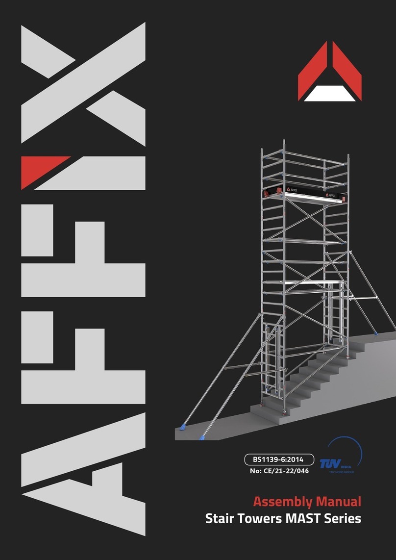
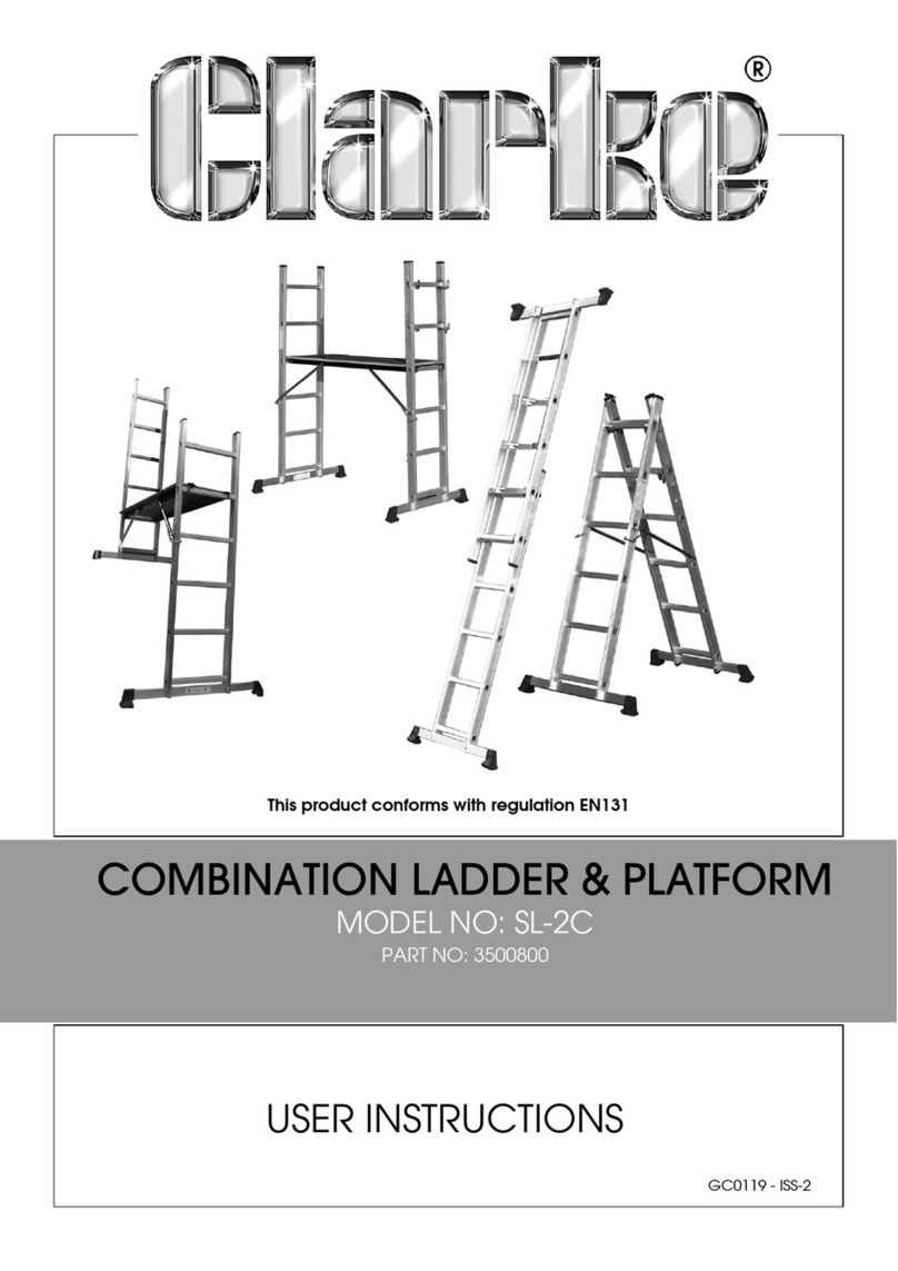
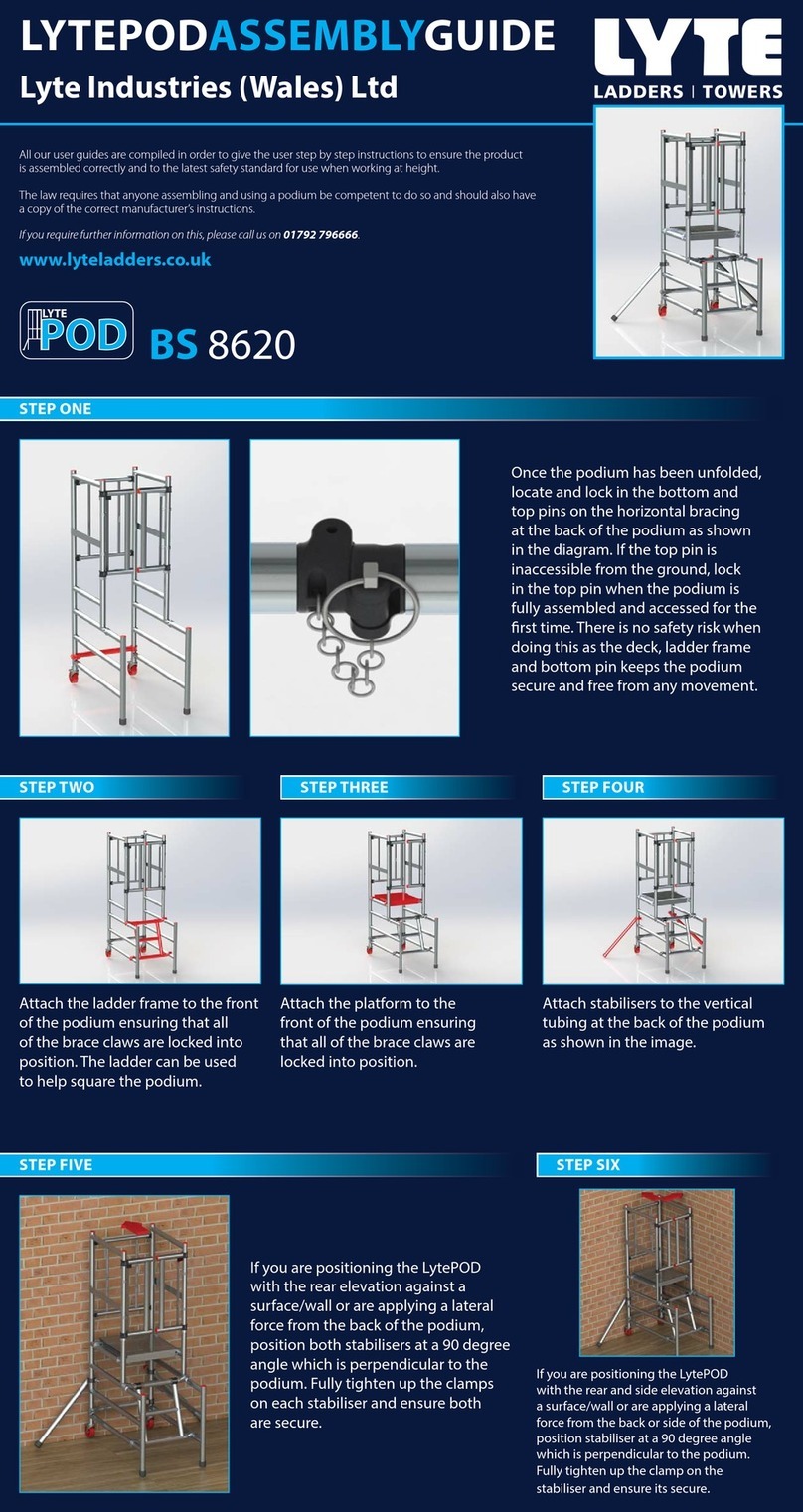
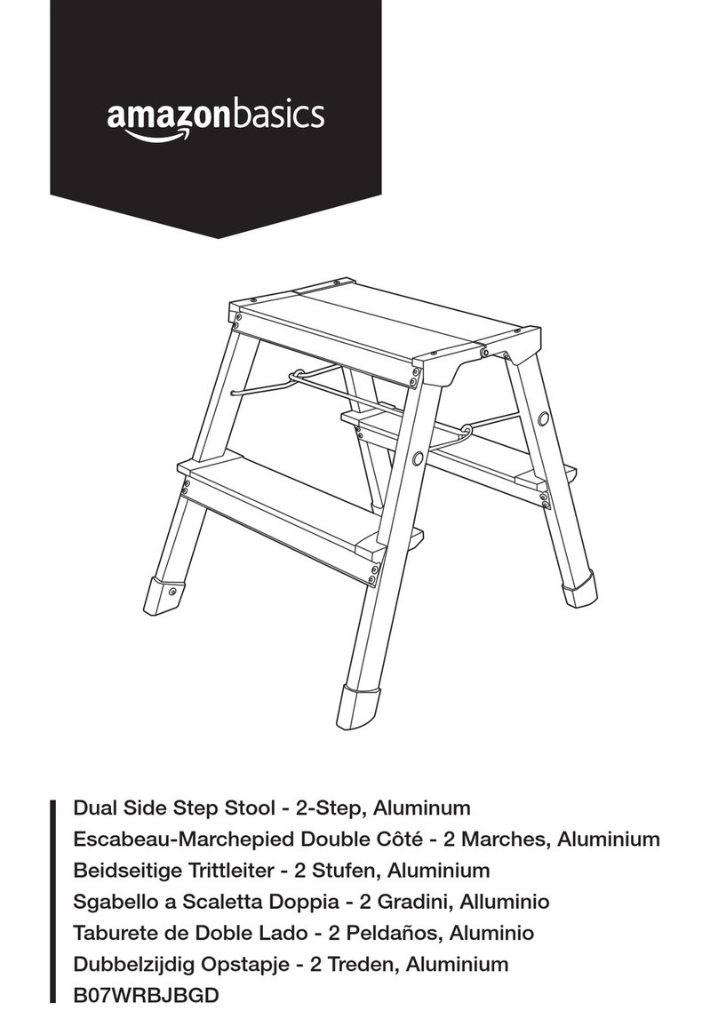
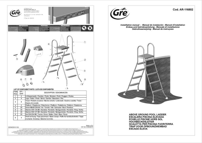
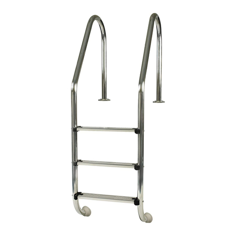
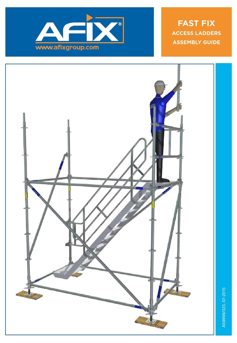
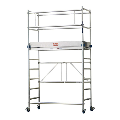
Euro Towers 3T User manual

Before You Start
• Familiarize yourself with these instructions paying attention to
these safety notes before you use the equipment supplied. Mo-
bile towers may only be assembled and dismantled by persons
familiar with these instructions.
• You will require the following Personnel Protective Equipment
(PPE) to help avoid personal injury, Hard Hat, Safety Gloves,
Safety Shoes or Boots.
• Inspect the individual components to ensure that they are not
damaged and that they function properly. Damaged components
shall not be used. Only use genuine Euro Towers components
with this tower, incorrect components shall not be used.
• Check the quantity of components supplied corresponds correct-
ly to the kitting list of the tower height you are planning to build.
Do not start assembly if you do not have the correct number of
components. Do not use any tower that has missing or damaged
parts or has not been properly assembled.
• Check the surface on where you are going to assemble the
tower is clear of excessive debris and can support the weight
of the tower, equipment and persons to be on the tower. Do not
assemble the scaold tower on unstable ground such as drain
grates, covers or duct covers or objects such as loose bricks,
boxes or blocks.
• Check for overhead hazards such as power lines. Do not
assemble a tower near un-insulated, live or energised electrical
machinery or circuits, or near machinery in operation.
• Euro Towers recommend a minimum of 2 persons to build this
tower system. For taller towers you may require additional
persons.
• Mobile Scaold Towers are not designed to be lifted or suspend-
ed by a crane or any other lifting device.
Inspection, Maintenance and Transport
• Regularly inspect the individual components to ensure that they
are not damaged and that they function properly. Damaged
components shall not be used and shall be removed from use.
Damaged components should be replaced, sent for repair or be
destroyed.
• Inspect all tubes on frames, stabilizers and braces for dents, cuts
and holes, damaged equipment should not be used. Check all
joints for cracked welds and that they are secure.
• Inspect brace hooks, check the clicker works freely, and that the
hook is not distorted from abuse. Check the brace is not bent
out of shape.
• Inspect platforms for damage to the decking and xings, and that
(if tted) trapdoors open and close freely. Check the aluminium
framework for damage and weld condition, look out for cracked
welds due to overloading. Check the hooks are not distorted
from abuse.
• Inspect stabilizer couplers tighten and can be loosened freely,
ensure rubber foot is in securely tted and not worn out, check
for adjusting pins on telescopic stabilizers are tted and secured.
• Inspect castors, checking that the wheel turns and spins freely,
that the brake engages and stops the wheel from spinning and
that the wheel has no at spots.
• Inspect the adjustable leg threads are clean from burrs and the
nut run freely up and down the thread. Check the nut housing for
abuse or missing nodules.
• Light oil or a lubricating spray may be used to free up jammed
clickers, castors, adjustable leg nuts, trapdoor hinges and
latches.
• When transporting the components do not use excessive
strapping forces when securing the load, this may distort
components if not done properly.
Further information on inspection and maintenance can be found
on Euro Towers Inspection Posters. For further safety information
or downloading instructions call Euro Towers or visit our website.
Assembly & Dismantling
• All components should be passed up or down by hand where
possible, where this is not possible use a suitable material for
lifting (e.g. Heavy, corded rope) and sucient knot ties (e.g. Hitch
knot or Timber Hitch). Do not use mechanical hoists.
• Always climb the inside of the tower using the ladders provided.
Never climb up the outside on any tower.
• If outside be aware of adverse weather or windy conditions. Be
aware of changes to the environment in which you are using your
tower that could make it unsafe.
• Do not lean ladders against the tower or climb the outside of the
tower, only ascend and descend via the supplied access system
from inside the tower, use the trapdoor for access.
Safe Use
• Should you require additional platform height, add further
components. Never extend your adjustable legs to achieve extra
height, these are for levelling only. Never use a ladder or other
objects on the platform to achieve additional height.
• Before use, check that all components listed have been used in
the tower in the correct position.
• Be aware of imposing side loads onto your tower by the work you
are carrying out, such as the use of power tools or high-pressure
jets. The maximum side load allowed is 20Kg.
• Do not exceed the safe working load of the platform or structure
by accumulating debris, material or tools on platforms as these
can be a signicant additional load. Loads must be evenly spread
and not block trapdoors.
• It is not permissible to attach and use hoisting facilities on towers,
unless specically provided for by Euro Towers Ltd.
• Never climb on horizontal or diagonal braces. Do not gain access
or descend from the working platform other than by the included
access system. Never jump on to or o platforms.
• Guardrails and Toeboards must be tted to working platforms.
• It is not permissible to attach bridging sections between a scaold
tower and a building.
Stability
• Ensure that the scaold tower is always level and the adjustable
legs are engaged. Check that you have taken all necessary pre-
cautions to prevent the tower being moved or rolling away. Always
apply all castor brakes or use base plates.
• Ensure that the scaold tower is within the maximum platform
height as stated, and that the appropriate stabilizers are tted.
• A scaold tower must not be used or moved in winds stronger
than 7.7 meters per second. Beaufort scale 4. (17mph).
• If the wind speed is likely to get up to or exceed 25mph the tower
should be tied to a suit adjacent structure, if no structure is availa-
ble you must dismantle the tower completely before it is exposed
to these strong winds.
• When moving a tower plan the route, remove all persons and
equipment from the tower, walk the route checking that the
ground can take the weight of the tower and looking out for ob-
structions and hazards on the ground and overhead. If you have
any doubt about the route dismantle the tower and re-assemble in
the new required location.
• To move a tower safely, adjust the top clamp of the stabilizers and
lift the rubber foot no more than 25mm from the ground, release
the braked wheels and push the tower at normal walking speed
to the required position. Once in position reapply brakes, level
tower and reposition all stabilizer feet to ensure rm contact with
the ground. The maximum height you can move a tower is 4.2m
platform
• Ballast weights can be used where it is not possible to t the
required stabilizers. They must be solid materials and cannot
be granular or liquid, they must be secured to the tower and
placed as low down as possible, this can be on extra platform(s).
Stabilizers or Ballast weights must be used when stated in the kit
list. For further information on the use of Ballast Weights contact
your supplier or Euro Towers Ltd.
GENERAL SAFETY RULES
KLIK DOUBLE WIDTH LADDER FRAME
3T - THROUGH THE TRAPDOOR METHOD
TUV CERTIFIED QUALITY SYSTEM
TO ISO 9001:2015
GS PRODUCT APPROVAL TO
BS.EN.1004 3 8/12 XXXD
INSTRUCTIONS FOR USE TO BE
FOLLOWED CAREFULLY
MAX SAFE WORKING LOAD FOR TOWER 750KG
MAX SAFE WORKING LOAD PER PLATFORM 250KG
Euro Towers Ltd, Unit 5 Edgemead Close, Round Spinney, Northampton, NN3 8RG JUNE 19
NEVER CLIMB A MOBILE TOWER
ON THE OUTSIDE OF THE FRAME
MANUFACTURED BY EURO TOWERS LTD
Trapdoor Platform
Side Toe-Board
Plain Frame
3, 4 or 5 Rung
Diagonal Brace
2M White / Green / Red
2.5M White / Green / Yellow
3M White / Green / Blue
Castor / Adjustable Leg
Stabiliser
Ladder Frame
3, 4 or 5 Rung
End Toe-Board
Horizontal Brace
2M Black / Green / Red
2.5M Black / Green / Yellow
3M Black / Green / Blue

JUNE 19
LADDER FRAME SCAFFOLD TOWER DOUBLE WIDTH KIT LIST
AVAILABLE IN THREE LENGTHS: 2m, 2.5m or 3m
This range of Double Width Klik Towers gives an exceptional versatile system ideal for working in normal applications.
All frames can be used as uppers or lowers, simply place the platform on the third rung below the top of the tower
and the correct guardrail height is achieved.
The platform levels marked * indicate that these
platforms and handrails are repositioned.
PLEASE NOTE
If temporary platforms are used during assembly, reposition them during dismantling.
MOVING A TOWER Remove people and materials from the tower, and reduce the height of the
tower to 4.2m. Adjust and raise the stabilizers 25mm from the ground, ensure the couplers are tight,
and push from at or near the base by manual eort only, never use mechanical means. Recheck
level and reposition stabilizers before use.
MAXIMUM VERTICAL DISTANCE BETWEEN PLATFORMS MUST NOT EXCEED 4M

DOUBLE WIDTH LADDER FRAME ERECTION INSTRUCTION MANUAL
The tower requires a minimum of 2 people for assembly; do not attempt to assemble a tower by yourself
JUNE 19
Fit in 2 horizontal braces to the vertical member
of the frames, as low as possible, below the 1st
rung. All horizontal braces t on from inside the
tower facing out.
Insert two Adjustable legs and castors into your
base frames.
1. 2. 3. 4. 5.
6. 7. 8. 9. 10.
11. 12. 13. 14. 15.
16. 17. 18.
Lock all 4 castors. Fit 2 diagonal braces from the 1st rung to the 3rd.
Braces should be added in a continuous pattern.
When tting a full intermediate work platform it is
permissible to interrupt the continuous pattern.
Fit plain platform on appropriate rung of frame.
See tower kit guide for illustration. This will
indicate which rung to t trapdoor platform
depending on nal tower height.
Level your tower using a spirit level as a guide.
The scaold must be verticle in both planes
within an inclination of 1%
Fit four horizontal braces at appropriate height.
Two on the outside hooks outwards and two
in the middle of the tower as shown, hooks
downwards.
On lower levels this may not be required.
To add further frames, stand on the platform
disengage your interlock clips and add your
frames ensuring the ladder is continuous.
After adding frames, always remember to
engage all interlock clips.
Fit diagonal braces to continue in a regular
pattern. Double width towers always have
diagional braces either side of the tower
opposing each other as illustrated.
Secure stabilisers as soon as possible to
increase tower stability. Check tower kit list to
ensure the correct stabilisers are tted.
Fit trapdoor platform on appropriate rung.
See tower illustration guide.
From a seated position, using the through
the trapdoor (3T) method, t four horizontal
braces. Two on the frame verticle hooks facing
out and two in the middle hooks facing down
as show.
Continue erecting tower to nal tower height
repeating the 3T process as illustrated. Always
ensure that there is side protection to prevent falls.
Maximum verticle distance between platforms
must not exceed 4m.
Remove the plain platform from the base of
your tower and reposition to appropriate rung,
3rd rung down from the top.
Position trapdoor platform alongside the plain
platform.
From a seated position, using the through the
trapdoor (3T) method, t four horizontal braces
to the verticle member of the frames above the
appropriate rungs, hooks facing out.
When handrails have been correctly tted, t
the toe-boards.
When INTERMEDIATE PLATFORMS are to
be used as working platforms, t a plain
platform beside the trapdoor platform,
ensure there are guard rails and mid rails
on both sides of the tower and that
toeboards are used.
Dismantling is the reverse except when dismantling
the handrails. Unclip the four end hooks and from the
sitting position remove the handrails.
Do not remove the handrails whilst standing on the
platform, this would leave you at risk.
Other Euro Towers Ladder manuals


