euro verbau EG PV 4000 User manual
TRENCH SHORING SYSTEMS FROM SHORING PROFESSIONALS
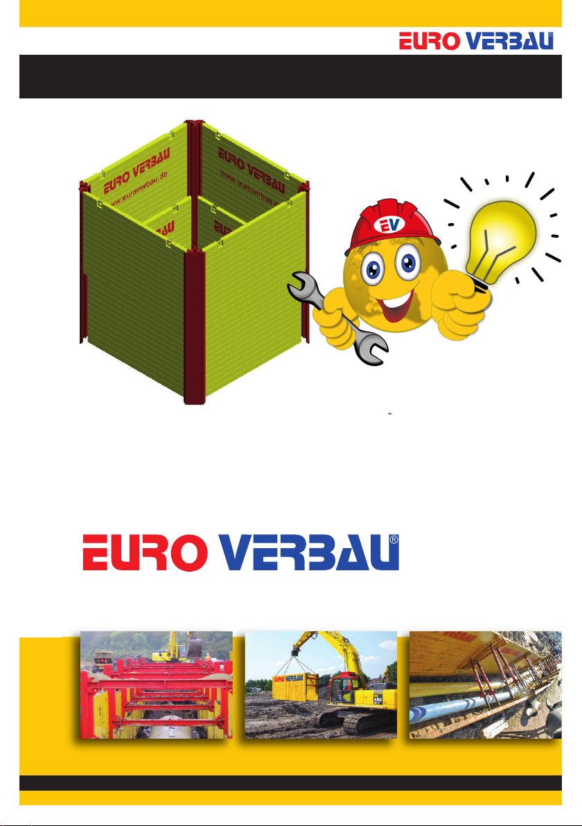
Trench shoring equipment
Production - Sales - Rental - Service
MANUAL
GmbH
CORNER SLIDE RAIL SYSTEM
EG- / DG-CORNER
Hoc ks teiner Weg 30
Tel:
+49 21 66-3 98 63 60
Site:
www.euroverba u.de
D-41189 Mönchengladbach
Fax:
+49 2166-3 98 63 78
Mail:
info@euroverb au.de
MANUAL
CORNER SLIDE RAIL SYSTEM EG-CORNER / DG-CORNER
2
These instructions for use must be presented to the bui ding site personne .
1. Genera purpose of use
Shafts and excavations with head shoring.
2. Specifications EG PV 4000
Description Type Dimensions [mm] Weight [kg]
Single-corner slide rail EG corner L=3 00 189
Double-corner slide rail DG Corner L=4 00 469
Double-corner slide rail DG Corner L= 00 73
3. Safety regu ations
We refer to the fact that the above shoring system is only for the intended use and may only be
assembled, installed, dismantled and extracted in the sequence listed under the following points,
exclusively with the use of all relevant ”original construction elements”. The shoring plates used are
slide-rail plates of the KRA/KRI VS 100 type (plate thickness 10 mm) and KRA/KRI VS 120 (plate
thickness 12 mm).
Failure to obeserve these unser instructions make the manufacturer’s liability and warranty are invalid.
Observe the load-bearing capacity of the shoring elements.
Note:
All of the requirements of BG-Bau (the professional association) as well as DIN 4124 ”Excavations and
trenches, embankments, workroom widths, shoring” are applicable. In the event of conditions deviating
from the standard conditions, construction site statics must be prepared.
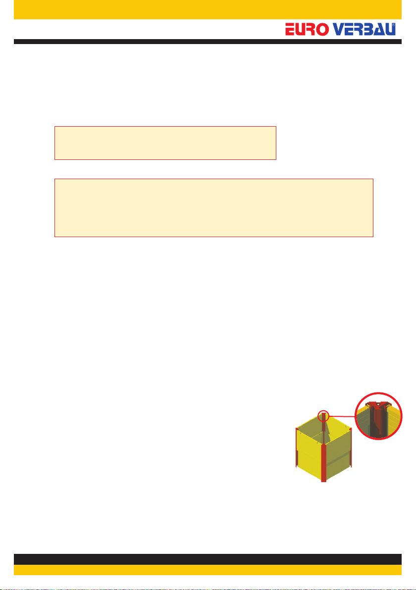
4. Shoring widths for sing e pits, EG (single slide ail) or DG (double slide ail) corner
Shoring widths for EG corner
Shoring plate bc b b
Inner plate [mm] Trench width [mm] Outer rail [mm]
Shoring widths for DG corner
Shoring plate bc b b
Inner plate [mm] Trench width [mm] Outer rail [mm]
WARNING
Trench shoring equipment
Production - Sales - Rental - Service
KRA
KR 8000 8185
KR 7000 7210
KR 6000 6210
KR 5000 5210
KR 4500 4710
KR 4000 4210
KR 3500 3710
KR 3000 3210
KR 2500 2710
KR 2000
KRI
8090
7106
6106
5106
4606
4106
3646
3146
2646
2146 2210
KRI KRA
8485
7460
6460
5460
4960
4460
3920
3420
2920
8390
7356
6356
5356
4856
4356
3856
3356
2856
2356 2420
8437
7433
6433
5433
4933
4433
3933
3433
2933
2433
KR 8000
KR 7000 7106 7210
KR 6000 6210
KR 5000 5210
KR 4500 4710
KR 4000 4210
KR 3500 3710
KR 3000 3210
KR 2500 2710
KR 2000
6106
5106
4606
4106
3646
3146
2646
2146 2210
KRI KRA
8090 Innenplatte
KRI KRA
8737
76567760 7733
66566760 6733
56565760 5733
51565260 5233
46564760 4733
41564220 4233
3656 3720 3733
31563220 3233
26562720 2733
8785 Außenplatte

Trench shoring equipment
Production - Sales - Rental - Service
MANUAL
CORNER SLIDE RAIL SYSTEM EG-CORNER / DG-CORNER
3
Excavation with outside walert and foot rest (lost)
5. Insta ation
a) Depending on the soil conditions, create an advance excavation for the pit. Set up one plate and se-
cure it against falling over or hold it in position with a second machine
b) Thread one corner slide rail at one end of the plate, into the outer guide, push in with the excavator
and secure it. Insert one plate at right angles to the first plate.
c) Thread the second corner slide rail into the outer guide, push in with the excavator to secure it.
d) Repeat steps C and D on the other side. Make sure that the two plates are at right angles to the head
plate. Insert 2 corner rails on the free plate ends and press them down.
e) Insert one plate into the outer guides of the corner rails. Align the pit system. Lower the plates and
corner rails gradually. At a depth of approx. 2.3 m, affix a support plate to the EG corner, secure it with
bolts and gradually lower it. Max. depth 3.7 m. If necessary, use protection rails and a protection anvil.
On the DG corner, the additional plates in the inner guide are built into the DG corner. At greater
depths, a top plate can also be used in the outer guide. The maximum depth is 6.1m. The plates should
lead ahead of the corner slide rails so that the guides of the slide rail remain free.
Image 2a Image 2b Image 2c
a)b)c)
d) e) e)

Trench shoring equipment
Production - Sales - Rental - Service
MANUAL
CORNER SLIDE RAIL SYSTEM EG-CORNER / DG-CORNER
4
f) If the plate head has reached the upper edge of the pit, in-
sert a second plate into the inner guide of the corner slide
rail if necessary, as far as the height of the blade of the first
plate. Press in the inner plate further, as described in e) If
necessary, slide support plates into the outer slide-rail guide
and connect them to the lower plate by means of locking
bolts and safety clips.
g) When the excavation is finished, the plate head should lie
approx. 10 cm above the base and serve as a scree pro-
tector.
6. Dismant ing
a) Insert the backfill material in layers (observing the compac-
tion level).
b) Pull out the plates and corner slide rails up to the filled
area. In doing so, start from the inner plate. The height of
the respective pullout is according to compaction level.
c) Compact the backfill material.
d) Restart at point 6.a, until the shoring iscompletely pulled
out of the earth.
7. Disassemb y
Before transporting away the shoring unit, it is disassembled
analogously to the assembly but in the reverse sequence.
8. Maintenance / Service
On each disassembly, the corner rails should be cleaned. The
entire shoring unit must be protected against corrosion cau-
sed by handling damage by the use of appropriate protective
measures.
9. Transport
When unloading, you should store the supplied wooden
blocks and the rubber plates appropriately. These parts must
always be re-used for the return transport. As the shipper, you
are co-responsible for the appropriate shipping of the return
transport.
©2012 EUROVERBAU • Die hie ve öffentlichten Inhalte sind u hebe echtlich geschützt. De Inhalt da f ohne sch iftliche Genehmigung de He ausgebe wede bea beitet, übe setzt, ve vielfältigt ode ve b eitet we den. 2012A
Manufacturer Certification in Compliance
with DIN EN 1090-2
f)f)g)
Table of contents


