EURO ED4EW Guide

533166 Libretto P -4P -6 neutro AUSTRALIA.FH11 Fri Feb 22 09:25:48 2008 Pagina 1
Colori compositi
INSTALLATION AND USER INSTRUCTIONS
NOTE TO INSTALLER: LEAVE THE OWNERS GUIDE MANUAL WITH THE APPLIANCE.
(Keep For Fu ure Reference)
- AU -

533166 Libretto P -4P -6 neutro AUSTRALIA.FH11 Fri Feb 22 09:25:48 2008 Pagina 2
Colori compositi

533166 Libretto P -4P -6 neutro AUSTRALIA.FH11 Fri Feb 22 09:25:48 2008 Pagina 3
Colori compositi
INDEX
INSTALLATION INTRUCTIONS...................pag. 3 - 7
SERVICE INSTRUCTIONS..........................pag. 8 - 9
USERS INSTRUCTIONS .............................pag. 10 - 14
ENVIRONMENTAL WARNING
Waste packaging
Do no hrow he packaging of your appliance in o he dus bin, bu pick
ou he differen ma erials (e.g. foil, paperboard, polys yrene) according
o he local rules for rubbish elimina ion.
This appliance mus only be used for he purpose of domes ic cooking.
WHERE THIS APPLIANCE IS INSTALLED IN MARINE CRAFT OR
IN CARAVANS IT SHALL NOT BE USED AS A SPACE HEATER.
DO NOT SPRAY AEROSOLS IN THE VICINITY OF THIS APPLIANCE
WHILE IT IS IN OPERATION.
Congratulations on he purchase of your new Hot Plate
which is buil o give you years of sa isfac ory service and pleasure when properly cared for and used.
Producing an efficien Ho pla e ha conserves energy required a considerable inves men of ime, effor and money.
Your Ho pla e is engineered o surpass all performance and safe y requiremen s. However, safe y is also YOUR responsibili y
hrough proper use and care.
Wi h his in mind, i is impor an ha you read his bookle . Acquain yourself wi h he fea ures and follow he use and care
sugges ions carefully for comple e sa isfac ion.
Remember: only authorised personnel must make the necessary gas and electrical connections.
Be sure you know he correc model and serial model of your Ho pla e. The da a pla e is sealed on he ou side of he lower
case of your Ho pla e.
RECORD HERE FOR EASY REFERENCE
Model Colour Serial Number
Ins alla ion Da e
Dealer's Name and Address
3
- WARNING
This appliance is not intended for use by persons (including
children) with reduced physical, sensory or mental capabilities,
or lack of experience and knowledge, unless they have been
given supervision or instruction concerning use of the appliance
by a person responsible for their safety.
Children should be supervised to ensure that they do not play
with the appliance.

533166 Libretto P -4P -6 neutro AUSTRALIA.FH11 Fri Feb 22 09:25:48 2008 Pagina 4
Colori compositi
INSTALLATIONS INSTRUCTIONS
IMPORTANT NOTICE TO THE INSTALLER
GAS CONNECTION
The appliance shall be ins alled by an au horized person in accordance
wi h he manufac urers ins alla ion ins ruc ions, relevan local fi ing
regula ions, municipal building regula ions, he AS 5601 ( AGA 601
) gas ins alla ions. For gas burning appliances and equipmen and
o her relevan s a u ory code band regula ions. If you have some
doub s, please con ac he au hori ies for confirma ion concerning he
charac eris ics of he gas and elec rici y ou pu .
This appliance can be connec ed wi h rigid pipe as specified in AS5601
able 3.1 or wi h a Flexible Hose which complies wi h AS/ANZ 1869
(AGA Approved), 10mm ID, class B or D, no more ha 1.2m long and
in accordance wi h AS5601. Ensure that the Hose does not contact
the hot surfaces of the hotplate, oven, dishwasher or other
appliance that may e installed underneath or next to the hotplate.
The Hose should not e su jected to a rasion, kinking or
permanent deformation and should e a le to e inspected along
its entire length. Unions compati le with the hose fittings must
e used and connections tested for gas leaks. The supply
connection point shall e accessi le with the appliance installed.
The appliance is generally prese for na ural gas (so no o her adjus men
is necessary) and equipped wi h a regula or wi h pressure es poin .
Ensure ha all foreign ma er has been cleared from he gas supply
line and also purge all air from he gas sys em. Connec o regula or,
igh en and check he ins alla ion o ensure no gas leaks occur. Check
gas pressure, no e he correc se ing from he da a pla e sealed on
he lower side of he case. A duplica e label is supplied and adhered
o he fron of his ins ruc ion manual.
Four burner models: burner pressure is o be se a 1 kpa wok fas
burner only opera ing a full ra e. 5 burner models: "burner pressure
4 BURNER UNIT / 4 ELECTRIC PLATES
DIMENSIONS
Overall Heigh above work surface......................45 mm (13/4 in)
Wid h ........................................................580 mm (22 13/16 in)
Dep h........................................................500 mm (19 11/16 in)
Minimum space above ho pla e .........................600 mm (24 in)
5 BURNER UNIT
DIMENSIONS
Overall Heigh above work surface......................45 mm (13/4 in)
Wid h ........................................................860 mm (33 14/16 in)
Dep h........................................................500 mm (19 11/16 in)
Minimum space above ho pla e...........................600 mm (24 in)
CONNECTIONS
Gas..............................................................RC 1/2 (1/2" B.S.P.)
Elec ric igni ion...........1 mm2 3 core cable (3 amp fuse required)
4 Elec ric pla es ..................................... 2.5 mm2 3 core cable
Should conform o local gas au hori y requiremen s.
Also refer o rangehood manufac urers recommenda ions.
GAS HOT PLATE
is o be se a 1 kpa wi h middle fron and righ fron burners opera ing
a full ra e. Apply a manome er o he es nipple and rese he regula or
if necessary.
Do no forge o replace he es nipple screw and o leave he
ins ruc ions book wi h he user.
For he adjus men s o TLP or U-LPG gas, please opera e as specified
in he paragraph GAS CONVERSION AND ADJUSTMENT (Page.
8).
Impor an : several par s are pro ec ed wi h a special an i-scra ch film.
Please remove i before use.
This appliance from he fac ory sui able for NATURAL gas bu , if
necessary, can be adjus ed for U-LPG or TLP gas by au horised
person.
4
533166 Libretto P -4P -6 neutro AUSTRALIA.FH11 Fri Feb 22 09:25:48 2008 Pagina 5
Colori compositi
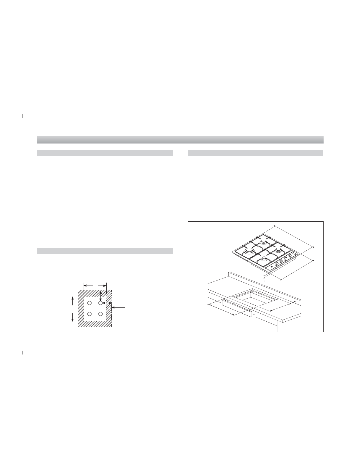
x - Cooking Surface Area
INSTALLATIONS INSTRUCTIONS
POSITIONING
The Ho pla e uni should be placed in a posi ion free from draugh s
and wi h good ligh . The uni mus no be fi ed closer han 30 mm
on lef hand side o non-combus ible cupboards or wall. No shelf
or overhang should be closer han 600 mm (23 5/8 in) above he
uni unless pro ec ed by a sui able fireproof ma erial. In addi ion,
here should be a clearance of a leas 110 mm (4 5/16 in) be ween
he back wall and he back edge of he uni .Pro ec ed Area: Any
combus ible surface wi hin his area, excep upward facing surfaces,
mus be pro ec ed by an approved noncombus ible ma erial.
The pro ec ed area ex ends:
(a) above he prohibi ed area by 150 mm ver ically for he full wid h
and dep h of he cooking surface area and; (b) horizon ally beyond
he edge of he cooking surface area o a poin 200 mm from any
burner, as shown, in he plan view, and o a heigh of 450 mm
above he op of he burner.
VENTILATION
Ven ila ion mus be in accordance wi h AS5601/AG 601 - Gas
Ins alla ions. In general, he appliance should have adequa e
ven ila ion for comple e combus ion of gas, proper flueing and o
main ain empera ure of immedia e surroundings wi hin safe limi s.
X
200 mm
X
PLAN VIEW
INSTALLATION 4 BURNER UNIT
This Ho pla e uni is sui able for ins alla ion in o a work surface
which has a minimum dep h of 600 mm (23 5/8 in) and which is
resis an o empera ure up o 100°C). Prepare a cu -ou in he
work op wi h dimensions 480 mm (18 7/8 in) back o fron and 560
mm (21 5/8 in) side o side. The cu -ou should no be less han 45
mm (1 3/4 in) from he rear edge of he work surface.
When he HP is ins alled here mus be a minimum clearance of
110 mm (4 5/16 in) be ween bo h he lef hand edge and he rear
edge of he Ho pla e and any adjacen walls or cabine s (See Fig.
1).
MEASURES APPLIANCE
MEASURES BUILDING-IN Fig. 1
20
5
500
30
580
480
560
533166 Libretto P -4P -6 neutro AUSTRALIA.FH11 Fri Feb 22 09:25:48 2008 Pagina 6
Colori compositi
INSTALLATIONS INSTRUCTIONS
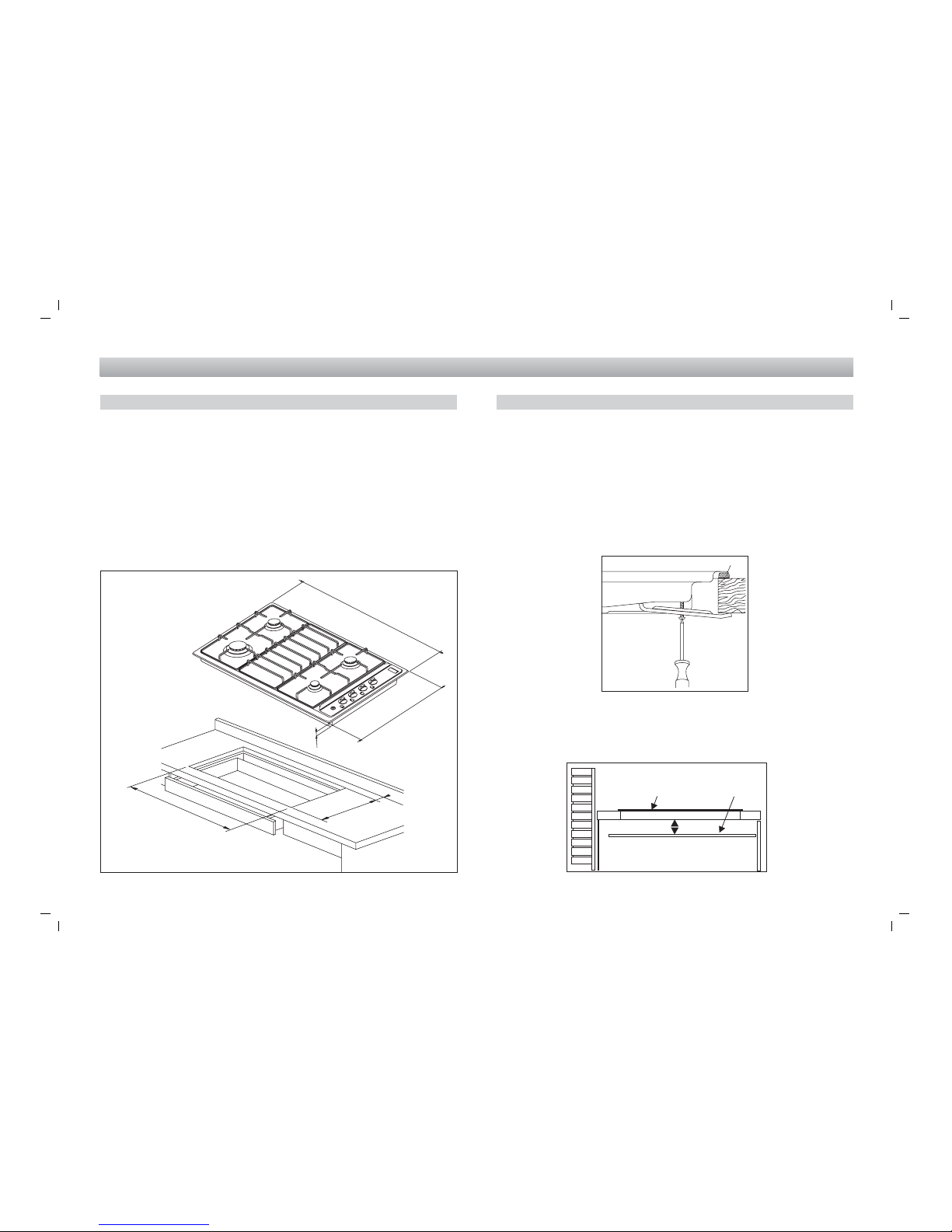
MEASURES APPLIANCE
MEASURES BUILDING-IN Fig. 2
INSTALLATION 5 BURNER UNIT
This Ho pla e uni is sui able for ins alla ion in o a work surface
which has a minimum dep h of 600 mm. (23 5/8 in) and which is
resis an o empera ures up o 100°C. Prepare a cu -ou in he
work op wi h dimensions 480 mm. (18 7/8 in) back o fron and
840 mm. (33 2/16 in) side o side. The cu -ou should no be less
han 45 mm. (1 3/4 in) from he rear edge of he work surface.
When he Ho pla e is ins alled here mus be a minimum clearance
of 110 mm. (4 5/16 in) be ween bo h he lef hand edge and rear
edge of he Ho pla e and any adjacen walls or cabine s (See Fig.
2).
BENCH TOP FIXINGS
The Ho pla e uni is fixed o he work op by me al clamps wi h a
self-adhesive rubber seal be ween he uni and he work op.
Ensure ha he self-adhesive seal is adhered o he underside of
he uni surface and near as possible o he ou er edge of he uni
as illus ra ed in Figs. 3. Secure he Ho pla e o he work op by
means of he fixing clamps and ensure ha he join be ween he
uni and he work op is air igh by igh ening he fixing clamps.
The clamps supplied are sui able for work ops wi h hickness from
25 o 40 mm. (1 in. o 1 9/16 in).
When he appliance is ins alled so ha he base can be ouched,
we recommend fi ing a pro ec ing shield. This shield mus projec
a leas 20mm from he lower par of he appliance and be capable
of wi hs anding he appliance empera ures.
min 20
gas ho pla e screening pla e
Fig. 3
Sealing S rip
6
480
840
500
30
860
20

533166 Libretto P -4P -6 neutro AUSTRALIA.FH11 Fri Feb 22 09:25:48 2008 Pagina 7
Colori compositi
INSTALLATION INSTRUCTIONS
GAS CONNECTION
The gas inle is RC 1/2 (1/2 in. B.S.P.) and is si ua ed a he rear
of he uni on he righ hand side. If necessary, cu a sui able hole
in he back of he cabine for he en ry of he gas supply and
elec ric cable.
IT IS RECOMMENDED THAT A SERVICE TAP AND UNION BE
FITTED ADJACENT TO THE APPLIANCE INLET TO FACILITATE
FUTURE SERVICING. ENSURE THE REGULATOR SUPPLIED
(FOR NATURAL GAS) IS FITTED BEFORE APPLIANCE.
Data Label
The Da a Label is loca ed base of he appliance. A duplica e Da a
Label is supplied o adhere in an accessible area nex o he appliance.
This appliance is sui able for Na ural Gas and U-LPG; ensure ha
he available gas supply ma ches he Da a Label.
VERY IMPORTANT FOR THE INSTALLER
Do no a emp o urn or s ress he hreaded elbow of he manifold:
you risk damage o his par of he gas appliance which may void
he manufac urers warran y.
BEFORE LEAVING - Check all connec ions for gas leaks wi h
soap and wa er. DO NOT use a naked flame for de ec ing leaks.
Igni e all burners o ensure correc opera ion of gas valves, burner
and igni ion. Turn gas aps o low flame posi ion and observe
s abili y of he flame. When sa isfied wi h he ho pla e, please
ins ruc he user on he correc me hod of opera ion. In case he
appliance fails o opera e correc ly af er all checks have been
carried ou , refer o he au horised service provider in your area.
Fig. 5
Elec ric diagram
for mul i-sparks
ligh er
ELECTRICAL CONNECTION
IMPORTANT
The wires in he mains lead are coloured in accordance wi h he
following code:
GREEN & YELLOW.........................................................EARTH
BLUE...........................................................................NEUTRAL
BROWN ..............................................................................LIVE
This ho pla e is supplied wi h a plug & cord, simply plug in o a 3
pin household socke ou le wi ch is properly ear hed. In order o
avoid hazard, any elec rical work performed on his equipmen or
i s associa ed wiring, should only be done be persons au horised
by he supplier or similarly qualified persons.
WARNING: THIS APPLIANCE MUST BE EARTHED.
The flexible mains lead and plug mus no be in con ac wi h ho
surfaces.
7
Elec ric diagram
for mul i-sparks
ligh er
533166 Libretto P -4P -6 neutro AUSTRALIA.FH11 Fri Feb 22 09:25:48 2008 Pagina 8
Colori compositi
SERVICE INSTRUCTIONS
SERVICING FOR HOT PLATES
Servicing shall be carried ou only by au horised personnel.
8
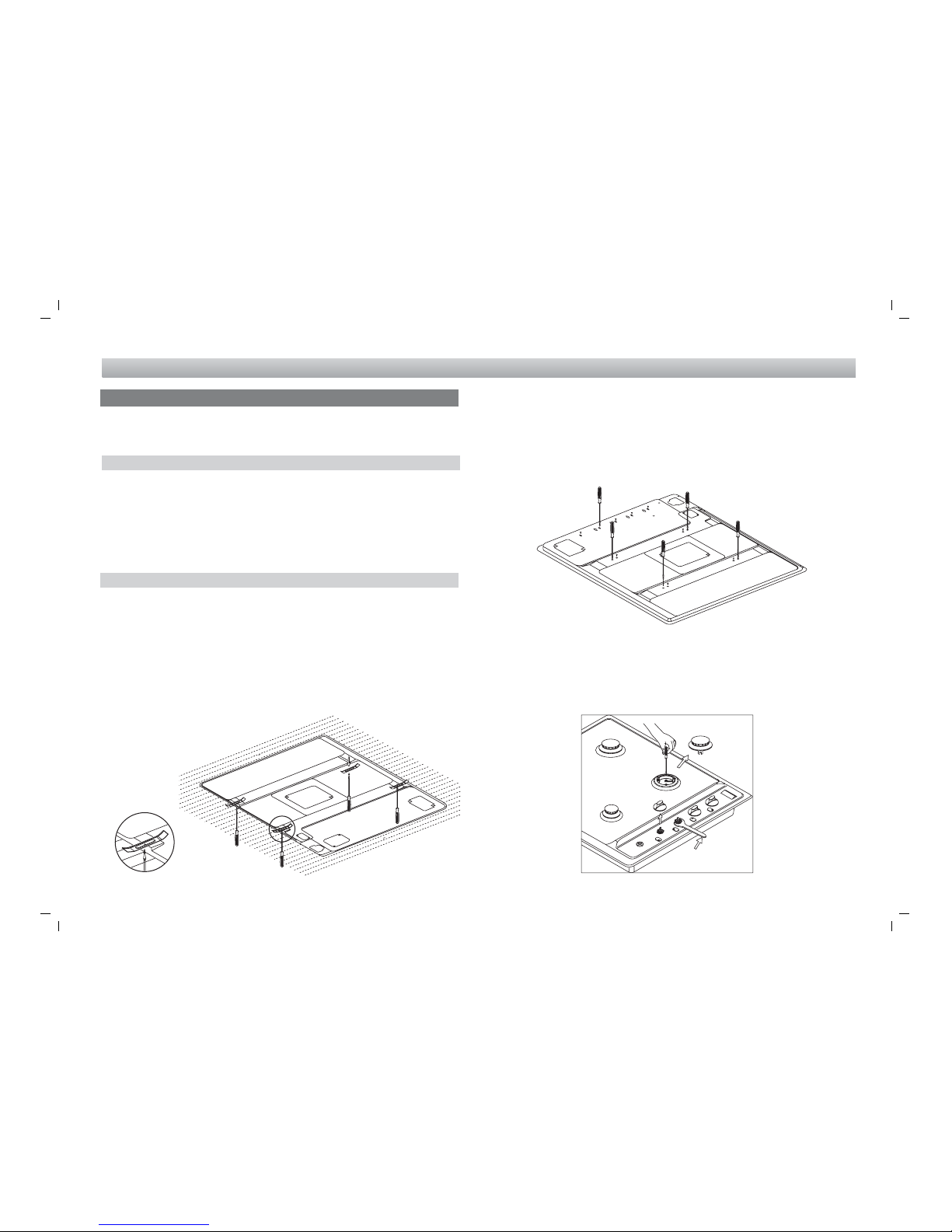
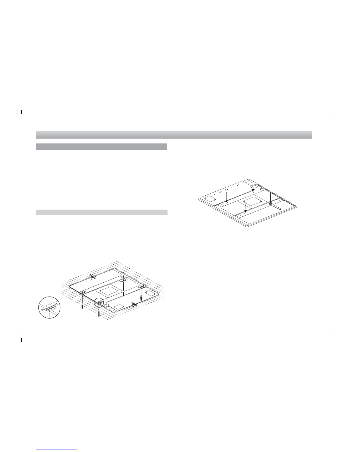
A) On he lower pla e of he hob, on he ou side here are some
visible screws fixing he burners and he gas manifolds o he
chassis or some screw-nu s fixing he elec rical pla es for all
elec ric or combined versions.
Once hese screws or screw-nu s are unscrewed, i is possible
o replace he componen s inside he hob (see pic ure below).
B)The hob is fixed in i s upper par o he burners by means of
some visible screws. If hese screws and he nu blocking he
aps o he hob are screwed, i is possible o open he appliance
and o reach he inside componen s (see pic ure below).
WARNINGS
Before performing any repair or operation switch the appliance
off and close the gas tap.
The manufac urer declines all responsibili y for any damage o
persons, animals or hings caused by failure o observe he rules
indica ed above. In case i is necessary o repair or replace he
inside componen s, ac as follows:
DISASSEMBLY OF WORK-TOP
- disconnec he elec rical supply cable
- disconnec he gas supply ube
- remove he grids
- remove burners and flame-spreaders
- remove he knobs from he facia-panel
- disassemble he work- op from he cabine unscrewing screws
blocking locking bridles.
Remove he hob from he op.
533166 Libretto P -4P -6 neutro AUSTRALIA.FH11 Fri Feb 22 09:25:48 2008 Pagina 9
Colori compositi
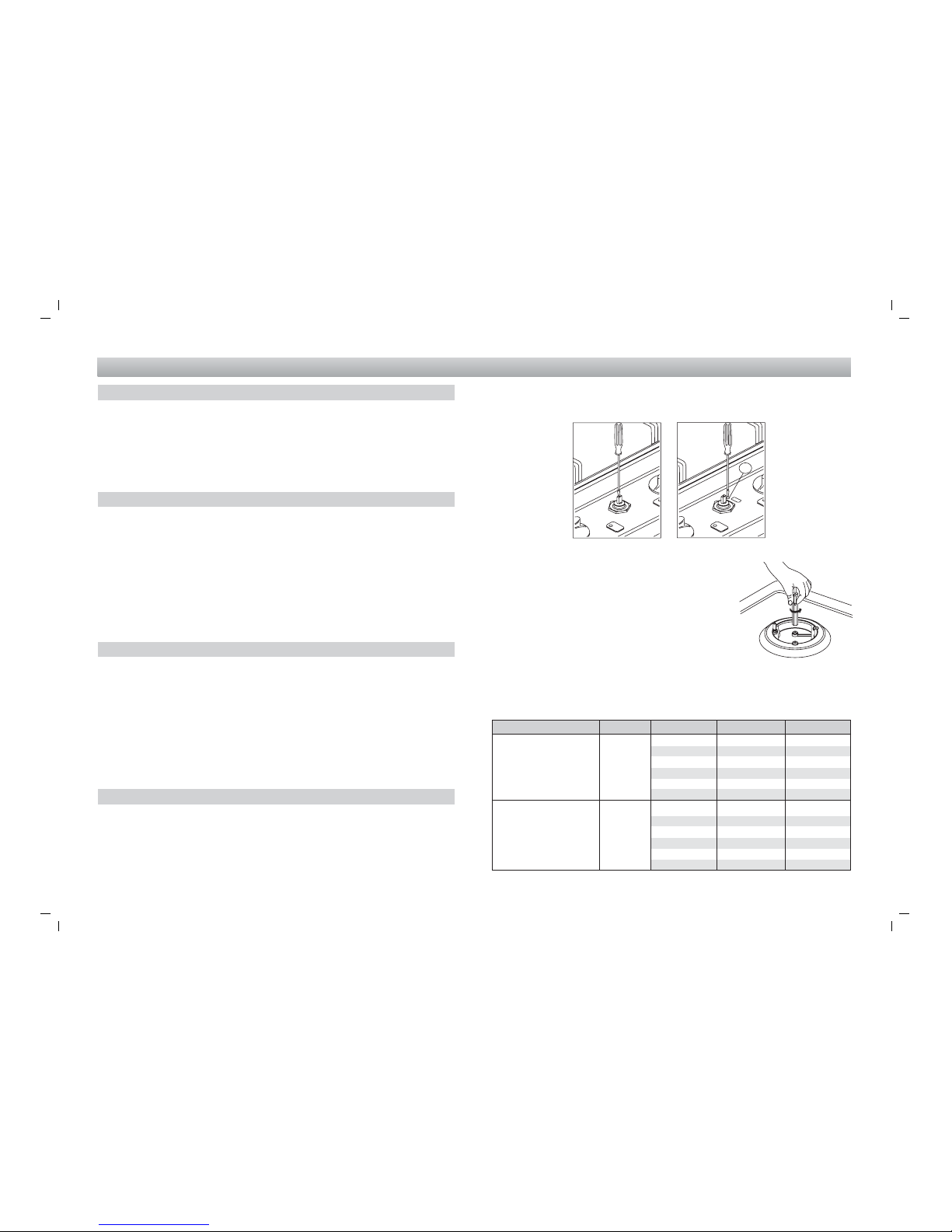
- Adjus he in ensi y of flame by loosening
or ligh ening screw A.
- For LP gas he screw A mus be comple ely
ligh ened.
- Make sure ha he flame does no
ex inguish passing quickly from he max.
flow (big flame) o he minimum flow (li le
flame).
- Assemble he knob again.
Fig. 10
GAS CONVERSION AND ADJUSTMENT
When used wi h na ural gas all burners have been prese a our
fac ory and fur her adjus men should no be necessary. Conversion
ki s o o her gases are available from he place of purchase. Do
no a emp o fi he conversion ki yourself. Conversion o LPG
or TLP gas should only be carried ou by an au horized echnician.
REPLACEMENT OF THE INJECTORS
When required o opera e on o her gas replace he injec ors in
accordance wi h informa ion referred o in char below (Fig.10).
In order o change he work- op injec ors, i is necessary o ac
as follows:
- remove he grids
- remove burners and flame-spreaders
- change he injec or (see Fig. 8) and replace i wi h ano her one
sui able for he new ype of gas.
SPECIAL NOTE
When conver ing from Na ural Gas o U-LPG ensure ha he NG
regula or is removed and replaced wi h he Tes Poin Assembly.
A gas regula or sui able for a supply pressure of 2,75kPa should
be par of he gas ank supply.
Af er ins alla ion or any servicing opera ion, always ensure ha
he appliance is gas sound and ha he componen s are now
opera ing correc ly. I ems removed during servicing should be
replaced in he reverse order o heir removal.
LOW POSITION ADJUSTMENT
- Swi ch he burner on, and urn he knob owards he minimum
flow posi ion (small flame).
- Remove he knob from he ap.
- In roduce a li le screwdriver in he ap rod (see pic ure).
A en ion: in aps wi h securi y valve, he minimum adjus ing screw
(A) is placed ou side he rod ap (see fig. 7).
Fig. 7
SERVICE INSTRUCTIONS
Fig. 8
A
9
Gas Type kPa Jet mm Ø Burners Power MJ/h
1,50 Quick 11,50
Na ural gas 1,00 1,14 Semiquick 6,50
0,85 Auxiliary 3,60
1,35 Fish 9,30
1,63 T. crown 13,70
0,95 Quick 11,80
Universal LPG 2,75 0,70 Semiquick 6,30
0,56 Auxiliary 4,00
0,80 Fish 7,90
1,05 T. crown 14,20

533166 Libretto P -4P -6 neutro AUSTRALIA.FH11 Fri Feb 22 09:25:48 2008 Pagina 10
Colori compositi
USER INSTRUCTIONS
USING THE GAS HOT PLATE
NOTE: This ho pla e is for domes ic use only (4 burner model
only)
4 GAS BURNERS
L
K
M
N
Q
R
A
B
E
C
10
S
L
K
M
N
Q
R
A
B
E
4 GAS BURNERS WITH TRIPLE CROWN
5 GAS BURNERS WITH LONG "FISH" BURNER
DESCRIPTION
A Work- op
B Lef grid for hob
C Rapid righ burner
E Semirapid lef burner
I Fish burner
F Cen ral grid for fish burner
K Semirapid righ burner
L Righ grid for hob
M Holder for mark label
N Gas knob
Q Igni ion bu on (some models only)
R Auxiliary burner
S Triple crown burner
M
N
A
B
Q
R
E
F
K
L
I
S

533166 Libretto P -4P -6 neutro AUSTRALIA.FH11 Fri Feb 22 09:25:48 2008 Pagina 11
Colori compositi
APPLIANCES WITH SAFETY VALVE
Follow he same procedure described above o igni e he burners. In
his case, however, once you have urned he knob o he open se ing,
hold i pressed in for 10 seconds. If for any areason he burner flame
goes ou , he safe y valve au oma ically shu s off he gas supply o
he burner in ques ion.
I is recommended ha pans sui able o he size of he burner should
de used as follows:
Large burner........................................................................13-24 cm
Small burner ........................................................................13-20 cm
Auxiliary burner ...................................................................12-18 cm
WARNING
I is no recommended o press push bu on for igni ion if all he
burners are no loca ed in he proper posi ions. The burner heads,
burner skir s and pan suppor s are removable for be er cleaning:
Always ensure ha he burner skir s and heads are replaced correc ly
so ha he burners func ion safely and correc ly.
During he use of he appliance pay a en ion ha wa er or any liquid
does no en er in o he appliance hrough he holes of he burners
or around he rods of he valves or he push bu on elec ronic ligh er.
Wa er or juice will produce dangerous shor -circui s and can seriously
damage he working of he Ho pla e. The base of he Ho pla e casing
will become ho in use and mus no be ouched hrough a drawer
or cupboard openings.
CLEANING
Cleaning should only be carried ou when he appliance is COOL
and is SWITCHED OFF. Always clean off spillage as quickly as
possible o preven burning which will make removal more difficul .
Do no use harsh abrasive rags or produc s; hey can seriously
damage he appliance. For Ho pla e op and enamelled pan suppor s
use a we clo h wi h liquid de ergen .
USERS INSTRUCTIONS
11
Automatic electric ignition (on some models)
To ligh he burner of he hob selec ed for cooking, push in he
corresponding knob and urn in he direc ion o he fully on posi ion
; when pressed fully in, he spark will be genera ed au oma ically,
igni ing he burner. To adjus he burner o he full-on posi ion, urn
he con rol knob clockwise o he appropria e se ing (marked wi h a
large flame symbol ).
Where his appliance is ins alled in marine craf or in caravans, i shall
NOT be used as a space hea er".
To urn he burner OFF, urn he con rol knob clockwise o he OFF
se ing (marked wi h a do ).
Manual ignition
To ligh he burner, place a ligh ed ma ch near he burner and urn
he appropria e knob an iclockwise o he low posi ion (marked wi h
a small flame symbol ) If burner does no igni e repea he procedure.
To adjus he burner o he full-on posi ion, urn he con rol knob
clockwise o he appropria e se ing (marked wi h a large flame symbol
).
Always use pans wi h all fla base diame er, which are well balanced
and s able in use, a pan which overhangs he ho pla e should no be
used. Avoid using old, misshapen pans, or pans which are uns able
when placed on a fla surface. Do no use spli pans as hey are
inheren ly uns able. To save gas, always posi ion pans cen rally over
he burners and adjus he flames so ha hey do no lick up he sides
of he panand only he base is hea ed. Always pu lids on a saucepans
and boil only he amoun of liquid you use. When he liquid has boiled
adjus he se ing o main ain a simmer. Do no ligh he burner un il
he pan is in posi ion and urn off he burner
before removing he pan. In hard wa er areas,
descale ke les regularly. For safe y, keep
saucepan handles urned o a safe posi ion
so hey are ou of reach of small children and
canno be acciden ally knocked. Fig. 15

533166 Libretto P -4P -6 neutro AUSTRALIA.FH11 Fri Feb 22 09:25:48 2008 Pagina 12
Colori compositi
USERS INSTRUCTIONS
Fig. 16A
Fig. 16D
Fig. 16E
Af er cleaning, make sure
head C and covers A
and B are properly
placed on heir sea as
figure D and no off-
cen er as in figure E.
B
A
C
Fig. 16
burner cap
l cating pegs
n tch f r electr de
in burner head
electr de
Elec ric diagram
3 4 2 1 3 4 2 1
2145
S
1
2
3
4
S
1
2
3
4
N
L
3 4 2 1 3 4 2 1
S
1
2
3
4
S
1
2
3
4
N
L
HOB
3
1
1 Elec ric pla e - 2 Elec ric pla e commu a or - 3 Warning ligh pla e - 4 Terminal box
yellow-green
ELECTRIC HOTPLATE
IMPORTANT NOTICE TO THE INSTALLER
ELECTRICAL CONNECTION
All connec ions o he supply mains should be made by
au horised personnel, in compliance wi h he regula ions in
force.
The ins aller will be responsible for complying wi h he safe y
regula ions.
The connection can also be made direct to the supply
mains by Installing-between the supply mains and the
appliance a switch having minimum 3mm distance
between the poles suitable for the power Input and
complying with the regulation In force.
Be sure ha he ear h wire is no in errup ed by he swi ch.
The supply cable mus no come in o con ac wi h any
componen s he empera ure of which exceeds he ambien
empera ure by 50°C. Before making any elec rical connec ion,
make sure ha :
he elec rical supply is correc for he appliance (see
specifica ions wri en on he da a pla e).
he fuses and your domes ic sys em are sui able for he
power requiremen s of he appliance (see da a pla e).
easy access o he plug or he swi ch is ensured once he
appliance is ins alled.
NOTE: Brown and black wires are bo h ac ive.
Da a pla e is glued on he underside of he Ho pla e.
Impor an : several par s are pro ec ed wi h a special an i-scra ch
film. Please remove i before use.
This appliance mus no be connec ed in egrally wi h any o her
appliance on he same sub-circui .
WARNING: THIS APPLIANCE MUST BE EARTHED.
NOTE: For cu ou dimensions see Pages 5 & 6.
12
BA
BA
533166 Libretto P -4P -6 neutro AUSTRALIA.FH11 Fri Feb 22 09:25:48 2008 Pagina 13
Colori compositi
13
SERVICING FOR HOT PLATES
17
USERS INSTRUCTIONS
NO
NO
These ins ruc ions are for a au horised person when i is necessary
o repair or adjus in ernal par s of he appliance.
WARNINGS
Before performing any repair or operation switch the appliance
off.
In case i is necessary o repair or replace he inside componen s,
ac as follows:
DISASSEMBLY OF WORK-TOP
3) On he lower pla e of he hob, on he ou side here are some
visible screw-nu s fixing he elec rical pla es o he chassis.
Once hese screw-nu s are unscrewed, i is possible o replace
he componen s inside he hob (see pic ure below).
1) Remove he con rol knobs (pulling up) from he elec ric he
swi ches
2) Disassemble he work- op from he cabine unscrewing screws
Z blocking locking bridles Y(see paragraph " Assemblage and
ins alla ion of he appliance".
Remove he hob from he op.

533166 Libretto P -4P -6 neutro AUSTRALIA.FH11 Fri Feb 22 09:25:48 2008 Pagina 14
Colori compositi
USERS INSTRUCTIONS
USING THE ELECTRIC HOB
USING THE HOT PLATES
The Ho pla e may have wo differen ypes of ho pla es; rapid
ac ion pla e compared wi h he s andard one, offers he advan age
of fas er hea ing and more power for fas er cooking The ho pla es
opera e a a fixed se ing according o he posi ion selec ed on
he con rol knob. To swi ch on, urn he appropria e con rol knob
o he required se ing (se ing 6 opera es a full ra e). To swi ch
off, urn he con rol knob o he OFF posi ion (marked ). The
elec ric pla e working is indica ed by a warning ligh on he con rol
panel. Turn he appropria e con rol knob clockwise o he required
se ing according o he cooking ask. The following able may be
used as a guide for se ings.
Setting Cooking Tasks
1 - Very low Warming, mel ing bu er or chocola e.
2 - Low S ews, milk pudding, cream sauces, fried
eggs.
3 - Low-medium S ewed frui , frozen foods, boiling milk.
4 - Medium Boiled po a oes, fresh vege ables soups, fish.
5 - High Large quan i ies of s ew e c. fish, omele es,
s eaks.
6 - Fas S eaks, escalopes, frying, boiling wa er.
WARNING
Always use pans wi h a fla base o ensure even con ac wi h he
ho pla e. The correc size of pan should be used so ha he whole
of he ho pla e is covered. Never swi ch on he ho pla es wi hou
a pan in posi ion, as he ho pla e will become dis or ed. To ensure
even con ac and o prolong he life of ho pla es, he base of he
pans should be kep clean and dry. Do no use spli pans as
uneven hea ing of he ho pla es will occur. For safe y, keep
saucepan handles urned o a safe posi ion so ha hey are ou
of reach of small children and canno be acciden ally knocked.
Take care never to reach over an electric hotplate and allow
time to cool before attempting to clean.
14
DESCRIPTION
ELECTRIC PLATE
A Work- op
F Elec ric pla e Ø 180 - lef
I Elec ric pla e Ø 145 - righ
L Holder for mark label
N Warning ligh for pla e
O Elec ric knob
R Elec ric pla e Ø 180 - righ
T Elec ric pla e Ø 145 - lef
M Holder for mark label
A
R
I
L
N
O
T
F

533166 Libretto P -4P -6 neutro AUSTRALIA.FH11 Fri Feb 22 09:25:48 2008 Pagina 15
Colori compositi
CLEANING
Cleaning should only be carried ou when he appliance is COOL
and is SWITCHED OFF. Always clean off spillage as quickly as
possible; o preven burning which will make removal more difficul .
Do no use harsh abrasive rags or produc s; hey Can seriously
damage he appliance. For Ho pla e op use a we clo h wi h liquid
de ergen and dry by means of a sof clo h. For elec ric ho pla es;
wipe wi h a clean clo h soaked in ho soapy wa er o remove
excess spillage. For s ubborn marks use a mild pas e cleaner or
mois soap pad. Dry he pla e horoughly af er cleaning. To main ain
he pla es, rub he surface wi h a li le neu ral oil periodically.
Ensure all cleaning agen s are horoughly removed.
FOR YOUR SAFETY
1) If you smell gas:
open he windows
don ouch elec rical swi ches
ex inguish any open flame
never use a flame o loca e such a leak, use soapy wa er
only
con ac au horised echnician.
2) Keep children away from he appliance: hey can suffer serious
personal harm by ouching he ho par s of he appliance and
he pans.
3) Don s ore i ems ha are a rac ive o children above or near
he appliance.
4) Do no s ore or use gasoline or o her flammable vapours, liquid
or i ems in he vicini y of his or any o her appliance.
5) In order o avoid any unin en ional fall down, pan handles
should be urned o he back of he cooker, no ou o he room
or over adjacen burners.
6) When cooking, don wear clo hes wi h flammable sleeves.
When this appliance is installed in marine craft or in
caravans it shall not be used as a space heater.
WARNING
Before i s firs use or, if he pla e has no been used for some
ime, i is necessary o elimina e he humidi y absorbed by he
insula ing layer mix ure. To provide for he drying of such, engage
he elec ric pla e for 30 minu es on posi ion 1 of he swi ch.
During he use or he cleaning of he appliance, pay a en ion ha
wa er or any liquid does no en er in o he appliance hrough he
holes around he rods of he swi ches. Wa er or juice or sauce
will produce dangerous shor -circui s and can seriously damage
he working of he Ho pla e. The base of he Ho pla e casing will
become ho in use and mus no be ouched hrough a drawer or
cupboard openings.
USERS INSTRUCTIONS
15

533166 Libretto P -4P -6 neutro AUSTRALIA.FH11 Fri Feb 22 09:25:48 2008 Pagina 16
Colori compositi
TROUBLE - SHOOTING GUIDE
16
USERS INSTRUCTIONS
a blown fuse or ripped circui breaker.
Ho pla e no properly grounded or polarized. This can effec
igni ion on spark igni ion models.
Check for power wa age.
Gas supply no connec ed or no urned on.
A pan is si ing on he burner gra e. This may par ially clock he
free air flow needed for combus ion. Remove he pan and ry
again.
Burners no adjus ed properly.
Food clogging burners or burner assembly misaligned. Make
sure ha burner por s on side of burner are no clogged. Make
sure ha burners are posi ioned correc ly.
WHEN YOU CALL FOR SERVICE
When you call for service or order par s for you Ho pla e be sure
o give:
1. MODEL
2. SERIAL NUMBER
3. COLOUR
4. PART NAME and/or descrip ion of problem
5. YOUR FULL NAME, ADDRESS, and HOME TELEPHONE
NUMBER and BUSINESS TELEPHONE NUMBER IF
APPROPRIATE
ABNORMAL OPERATION
Any of he following are considered o be abnormal opera ion and
may require servicing:
Yellow ipping of he hob burner flame.
Shoo ing up of cooking u ensils.
Burners no igni ing properly.
Burners failing o remain aligh .
Burners ex inguished by cupboard doors.
Gas valves, which are difficul o urn.
In case he appliance fails o opera e correc ly, con ac he
au horised service provider in your area.Burners ex inguished by
cupboard doors.
Gas valves, which are difficul o urn.
In case he appliance fails o opera e correc ly, call he number
on he da a label loca ed on he fron of his manual.
BEFORE YOU CALL THE SERVICE MAN
A review of he following may save you a service call and if no
i may help you explain he malfunc ion o he serviceman. Read
he opera ing ins ruc ions carefully. Be sure you know how to
opera the appliance.
If base of cooking u ensils show signs of carbon (soo ) deposi ,
his could indica e an incorrec burner flame. Please con ac local
service number (refer o he da a label on he fron of his ins ruci on
manual).
THE BURNER DOES NOT LIGHT
Check o ensure Ho pla e cord is plugged in o ou le . Check for
Tipoli ografia Mon agnani - I aly - Cod. 533166 1107
6."FOR NUMBER SERVICE CONTACT" SEE DATA LABEL
LOCATED ON BASE OF THE APPLIANCE
Maintenance schedule:
To ensure he appliance con inues o opera e a peak performance,
we recommend a rou ine service call every 2 years for he life of
he appliance.
Table of contents
Other EURO Cooktop manuals


Popular Cooktop manuals by other brands

Gaggenau
Gaggenau VG 264 220 CA installation instructions

Gaggenau
Gaggenau VG 264 234 AU instruction manual

Smeg
Smeg SAI63 instruction manual

Whirlpool
Whirlpool SC8640ED Use and care guide

Fisher & Paykel
Fisher & Paykel CE244C Installation instructions and user guide

Electrolux
Electrolux FPIC3677RF installation instructions


Clatronic
Clatronic EKI 3569 instruction manual

Kuppersbusch
Kuppersbusch EWI 457.1 installation instructions

Bompani
Bompani BO 297 MB/N Instructions for the installation and use

Miele
Miele KM 2312 Operating and installation instructions

Electrolux
Electrolux EW30IC60IS - 30" Induction Cooktop Manuel d’utilisation et d’entretien

Gaggenau
Gaggenau CI 283 instruction manual