EURO EG75GS Guide
INSTALLATION AND USER INSTRUCTIONS
NOTE TO INSTALLER: LEAVE THE OWNERS GUIDE MANUAL WITH THE APPLIANCE.
(Keep For Fu ure Reference)
X - GB -
Model No's
Montagnani - Modena - I aly - Cod. 534593 1107
USER INSTRUCTIONS
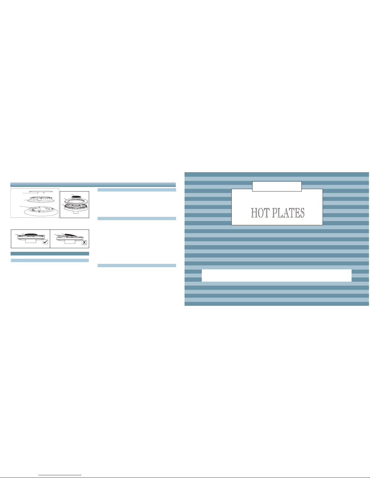
Fig. 16 Fig. 16A
After cleaning, make sure head C and covers A and B are
properl placed on their seat as figure D and not off-center as
in figure E.
TROU LE - SHOOTING GUIDE
EFORE YOU CALL THE SERVICE MAN
A review of he following may save you a service call and if no
i may help you explain he malfunc ion o he serviceman. Read
he opera ing ins ruc ions carefully. e sure you know how to
opera the appliance.
If base of cooking u ensils show signs of carbon (soo ) deposi ,
his could indica e an incorrec burner flame. Please con ac local
service number (refer back page).
THE URNER DOES NOT LIGHT
Check o ensure Ho pla e cord is plugged in o ou le . Check for
a blown fuse or ripped circui breaker.
Ho pla e no properly grounded or polarized. This can effec
igni ion on spark igni ion models.
Check for power wa age.
Gas supply no connec ed or no urned on.
A pan is si ing on he burner gra e. This may par ially block he
free air flow needed for combus ion. Remove he pan and ry
again.
Burners no adjus ed properly.
Food clogging burners or burner assembly misaligned. Make
sure ha burner por s on side of burner are no clogged. Make
sure that burners are positioned correctl .
WHEN YOU CALL FOR SERVICE
When ou call for service or order parts for our Hotplate be sure
to give:
1.MODEL
2.SERIAL NUMBER
3.COLOUR
4.PART NAME and/or description of problem
5.YOUR FULL NAME, ADDRESS, and HOME TELEPHONE
NUMBER and BUSINESS TELEPHONE NUMBER IF
APPROPRIATE.
Fig. 16E
Fig. 16D
burner cap
locating pegs
notch for electrode
in burner head
electrode
BA
BA
B
A
C
A NORMAL OPERATION
Any of he following are considered o be abnormal opera ion and
may require servicing:
Yellow ipping of he hob burner flame.
Soo ing up of cooking u ensils.
Burners no igni ing properly.
Burners failing o remain aligh .
Burners ex inguished by cupboard doors.
Gas valves, which are difficul o urn.
In case he appliance fails o opera e correc ly, con ac he au horised
service provider in your area.

211
INDEX
INSTALLATION INTRUCTIONS...................pag. 3 - 6
SERVICE INSTRUCTIONS..........................pag. 7 - 8
USERS INSTRUCTIONS .............................pag. 10 - 12
ENVIRONMENTAL WARNING
Waste packaging
Do no hrow he packaging of your appliance in o he dus bin, bu pick
ou he differen ma erials (e.g. foil, paperboard, polys yrene) according
o he local rules for rubbish elimina ion.
This appliance mus only be used for he purpose of domes ic cooking.
WHERE THIS APPLIANCE IS INSTALLED IN MARINE CRAFT OR
IN CARAVANS, IT SHALL NOT E USED AS A SPACE HEATER.
Congratulations on he purchase of your new Hot Plate
which is buil o give you years of sa isfac ory service and pleasure when properly cared for and used.
Producing an efficien Ho pla e ha conserves energy required a consider able inves men of ime, effor and money.
Your Ho pla e is engineered o surpass all performance and safe y requiremen s. However, safe y is also YOUR responsibili y
hrough proper use and care.
Wi h his in mind, i is impor an ha you read his bookle . Acquain yourself wi h he fea ures and follow he use and care
sugges ions carefully for comple e sa isfac ion.
Remember: only authorised personnel must make the necessary gas and electrical connections.
Be sure you know he correc model and serial model of your Ho pla e. The da a pla e is sealed on he ou side of he lower
case of your Ho pla e.
RECORD HERE FOR EASY REFERENCE
Model Colour Serial Number
Ins alla ion Da e
Dealer's Name and Address
USERS INSTRUCTIONS
CLEANING
Cleaning should only be carried ou when he appliance is COOL
and is SWITCHED OFF.
Always clean off spillage as quickly as possible o preven burning
which will make removal more difficul . Do no use harsh abrasive
rags or produc s; hey can seriously damage he appliance. For
Ho pla e op and enamelled pan suppor s use a we clo h wi h
liquid de ergen .
as hey are inheren ly uns able.
To save gas, always posi ion pans cen rally over he burners and
adjus he flames so ha hey do no lick up he sides of he
panand only he base is hea ed. Always pu lids on a saucepans
and boil only he amoun of liquid you use. When he liquid has
boiled adjus he se ing o main ain a simmer.
Do no ligh he burner un il he pan is in posi ion and urn off he
burner before removing he pan. In hard wa er areas, descale
ke les regularly. For safe y, keep saucepan handles urned o a
safe posi ion so hey are ou of reach of small children and canno
be acciden ally knocked.
WARNING
I is no recommended o press push bu on for igni ion if all he
burners are no loca ed in he proper posi ions. The burner heads,
burner skir s and pan suppor s are removable for be er cleaning:
Always ensure ha he burner skir s and heads are replaced
correc ly so ha he burners func ion safely and correc ly.
During he use of he appliance pay a en ion ha wa er or any
liquid does no en er in o he appliance hrough he holes of he
burners or around he rods of he valves or he push bu on
elec ronic ligh er.
Wa er or juice will produce dangerous shor -circui s and can
seriously damage he working of he Ho pla e. The base of he
Ho pla e casing will become ho in use and mus no be ouched
hrough a drawer or cupboard openings.
Where this appliance is installed in marine craft or in caravans,
it shall not be used as a space heater.
Do not spray aerosols in the vicinity of this appliance while
it is in operation.
1) If ou smell gas:
open the windows
dont touch electrical switches
extinguish an open flame
never use a flame to locate such a leak, use soap water
onl
contact authorised technician.
2) Keep children awa from the appliance: the can suffer serious
personal harm b touching the hot parts of the appliance and
the pans.
3) Dont store items that are attractive to children above or near
the appliance.
4) Do not store flammable products near the burners such as
fabric, cartons or plastic boxes and especiall aerosol containers.
5) In order to avoid an unintentional fall down, pan handles
should be turned to the back of the cooker, not out to the room
or over adjacent burners.
6) When cooking, dont wear clothes with flammable sleeves.
FOR YOUR SAFETY
DO NOT SPRAY AEROSOLS IN THE VICINITY OF THIS APPLIANCE
WHILE IT IS IN OPERATION.
- WARNING
This appliance is no in ended for use by persons (including
children) wi h reduced physical, sensory or men al capabili ies,
or lack of experience and knowledge, unless hey have been
given supervision or ins ruc ion concerning use of he appliance
by a person responsible for heir safe y.
Children should be supervised o ensure ha hey do no play
wi h he appliance.
10 3
INSTALLATIONS INSTRUCTIONS
IMPORTANT NOTICE TO THE INSTALLER
GAS CONNECTION
The appliance shall be ins alled by an au horized person in
accordance wi h he manufac urers ins alla ion ins ruc ions,
relevan local fi ing regula ions, municipal building regula ions,
he AS5601 ( AG601 ) - Gas Is alla ion . For gas burning appliances
and equipmen and o her relevan s a u ory code band regula ions.
If you have some doub s, please con ac he au hori ies for
confirma ion concerning he charac eris ics of he gas and elec rici y
ou pu .
This appliance can be connec ed wi h rigid pipe as specified in
AS5601 able 3.1 or wi h a Flexible Hose which complies wi h
AS/ANZ 1869 (AGA Approved), 10mm ID, class B or D, no more
ha 1.2m long and in accordance wi h AS5601. Ensure that the
Hose does not contact the hot surfaces of the hotp ate, oven,
dishwasher or other app iance that may be insta ed
underneath or next to the hotp ate. The Hose shou d not be
subjected to abrasion, kinking or permanent deformation and
shou d be ab e to be inspected a ong its entire ength. Unions
compatib e with the hose fittings must be used and
connections tested for gas eaks. The supp y connection point
sha be accessib e with the app iance insta ed.
The appliance is generally prese for na ural gas (so no o her
adjus men is necessary) and equipped wi h a regula or wi h
pressure es poin . Ensure ha all foreign ma er has been cleared
from he gas supply line and also purge all air from he gas sys em.
Connec o regula or, igh en and check he ins alla ion o ensure
no gas leaks occur. Check gas pressure, a duplica e label is
supplied and adhered o he fron of his ins ruc ion manual, no e
he correc se ing from he da a pla e sealed on he lower side
This appliance from he fac ory sui able for NATURAL gas bu , if
necessary, can be adjus ed for U-LPG or TLP gas by a compe en
licensed person.
5 URNER UNIT
DIMENSIONS
Overall Heigh above work surface ...................................45 mm
Wid h .........................................................................680 mm
Dep h.........................................................................510 mm
Minimum space above ho pla e ......................................600 mm
CONNECTIONS
Gas..............................................................RC 1/2 (1/2" B.S.P.)
Elec ric ......................1 mm2 3 core cable (3 amp fuse required)
Should conform o local gas au hori y requiremen s.
Also refer o rangehood manufac urers recommenda ions.
GAS HOT PLATE
USERS INSTRUCTIONS
To ligh he burner, urn he appropria e knob an iclockwise o he
low posi ion (marked wi h a small flame symbol ) and depress
he igni ion bu on and release. If burner does no igni e repea
he procedure. To adjus he burner o he full-on posi ion, urn he
con rol knob clockwise o he appropria e se ing (marked wi h a
large flame symbol ).
Where his appliance is ins alled in marine craf or in caravans,
i shall NOT be used as a space hea er".
To urn he burner OFF, urn he con rol knob clockwise o he
OFF se ing (marked wi h a do ).
B
A
A
B
C
Fig. 1
A-Burner cap
B-Lighting plug
C-Triple flame cap
APPLIANCES WITH SAFETY VALVE
Follow he same procedure described above o igni e he burners.
In his case, however, once you have urned he knob o he open
se ing, hold i pressed in for 10 seconds. If for any areason he
burner flame goes ou , he safe y valve au oma ically shu s off he
gas supply o he burner in ques ion.
I is recommended ha pans sui able o he size of he burner
should de used as follows:
urner minimum maxmum
diameter diameter
Large (rapid) 180mm 230mm
Medium (semi-rapid) 120mm 200mm
Small (Auxiliary) 80mm 160mm
Triple Flame 220mm 260mm
Always use pans wi h all fla base diame er, which are well balanced
and s able in use, a pan which overhangs he ho pla e should no
be used. Avoid using old, misshapen pans, or pans which are
uns able when placed on a fla surface. Do no use spli pans
of he case. 5 burner models: "burner pressure is o be se a 1
kpa wi h middle fron and righ fron burners opera ing a full ra e.
Apply a manome er o he es nipple and rese he regula or if
necessary.Do no forge o replace he es nipple screw and o
leave he ins ruc ions book wi h he user.
For he adjus men s o TLP or U-LPG gas, please opera e as
specified in he paragraph GAS CONVERSION AND
ADJUSTMENT (Page. 8).
Impor an : several par s are pro ec ed wi h a special an i-scra ch
film. Please remove i before use.
Dua trip e f ame version
no gas flow
maximum gas flow from central burner
minimum gas flow from central burner
maximum gas flow from outer and central burners
simultaneousl
minimum gas flow from outer and central burners
simultaneousl

4 9
INSTALLATIONS INSTRUCTIONS
POSITIONING
The Ho pla e uni should be placed in a posi ion free from draugh s
and wi h good ligh . The uni mus no be fi ed closer han 30 mm
on he lef hand side o non-combus ible cupboards or wall. No
shelf or overhang should be closer han 600 mm (23 5/8 in) above
he uni unless pro ec ed by a sui able fireproof ma erial. In addi ion,
here should be a clearance of a leas 110 mm (4 5/16 in) be ween
he back wall and he back edge of he uni .
Pro ec ed Area: Any combus ible surface wi hin his area, excep
upward facing surfaces, mus be pro ec ed by an approved
noncombus ible ma erial.
The pro ec ed area ex ends:
(a) above he prohibi ed area by 150 mm ver ically for he full
wid h and dep h of he cooking surface area and; (b) horizon ally
beyond he edge of he cooking surface area o a poin 200 mm
from any burner, as shown, in he plan view, and o a heigh of
450 mm above he op of he burner.
VENTILATION
Ven ila ion mus be in accordance wi h AS5601/AG601-Gas
Ins alla ions. In general, he appliance should have adequa e
ven ila ion for comple e combus ion of gas, proper flueing and o
main ain empera ure of immedia e surroundings wi hin safe limi s.
INSTALLATION
This Ho pla e uni is sui able for ins alla ion in o a work surface
which has a minimum dep h of 600 mm (23 5/8 in) and which is
resis an o empera ure up o 90°C). Prepare a cu -ou in he work
op wi h dimensions 480 mm (18 7/8 in) back o fron and 560 mm
(21 5/8 in) side o side. The cu -ou should no be less han 45 mm
(1 3/4 in) from he rear edge of he work surface.
When he HP is ins alled here mus be a minimum clearance of
110 mm (4 5/16 in) be ween bo h he lef hand edge and he rear
edge of he Ho pla e and any adjacen walls or cabine s (See Fig.
1).
MEASURES APPLIANCE
MEASURES BUILDING-IN Fig. 1
480
560
70 50
600
USER INSTRUCTIONS
USING THE GAS HOT PLATE
NOTE: This ho pla e is for domes ic use only.
2
5
3
6
2
4
1
3
4
2
1
2
5
3
2
6
1
5
6
5
2
1
x - Cooking Surface Area
X
X
PLAN VIEW
200 mm
Gas Type kPa Jet mm Ø urners Power MJ
1,50 Quick 11,00
Na ural gas 1,00 1,14 Semiquick 5,90
0,85 Auxiliary 3,50
0.78+1.75 T. crown 15,30
0.78+1.75 T. crown T.c. 15,30
0.78 Cen ral dual T.c. 2,20
0,95 Quick 11,00
propane 2,75 0,70 Semiquick 5,90
0,56 Auxiliary 3,50
0.44+1.05 T. crown 15,30
0.44+1.05 T. crown T.c. 15,30
0.44 Cen ral dual T.c. 2,20
680
510
1.Hob
2.Medium semi-rapid burner
3.Small auxiliar burner
4.Large rapid burner
5.Burner control knobs
6.Triple flame burner The hob contro knobs
The s mbols on the control knobs mean the following:
no gas flow
maximum gas flow
minimum gas flow
All operating positions must be set between the maximum and
minimum flow settings, and never between the maximum setting
and the closed position.
(s mbol present on version with lighting
integrated in the control knob.)
Instructions for use

8 5
INSTALLATIONS INSTRUCTIONS
When he appliance is ins alled so ha he base can be ouched,
we recommend fi ing a pro ec ing shield. This shield mus projec
a leas 20mm from he lower par of he appliance and be capable
of wi hs anding he appliance empera ures.
min 20
gas ho pla e screening pla e
Insertion and fixing
Before inser ing he hob in he ins alla ion opening, place he
special gaske around he bo om edge of he hob.
I is impor an o fix his gaske evenly, wi hou gaps or overlapping,
o preven liquid from seeping undernea h he hob.
1) Remove he pan s ands and he burner caps and urn he hob
upside down, aking care no o damage he igni ion plugs and
he hermocouples.
2) Place he gaske around he bo om edge of he hob as shown
in he illus ra ion on he righ fig.E).
3) Place he hob in he ins alla ion opening and push i down so
ha he hob is res ing firmly on he cabine , as shown in he
illus ra ion (fig.F).
The side springs will hold i in place.
4) Remove wi h a cu er he gaske in excess from he edges of
he hob (fig G).
Fig. G
a
a
Fig. F
A) gaske
SERVICE INSTRUCTIONS
The resul should be a small, homogeneous flame which is
uniform around he en ire burner ring. For he Dual Triple
Flame version see fig. P, by-pass 1 cen ral burner, by-pass
2 bo h burners.
5) Finally, check ha he burner does no go ou when he ap is
urned quickly from he maximum o he minimum posi ion.
LOW POSITION ADJUSTMENT
1) Ligh he burner as already described.
2) Turn he ap he minimum flame posi ion.
3) Remove he con rol knob.
4) Use a hin s raigh screwdriver o urn he by-pass pin loca ed
nex o he ap rod (see fig. M). For U-LPG, urn he by-pass
pin fully clokwise.
Fig. M Fig. P
A
A
1
2
B
Unscrew he screw " B " (fig. 6A) and disassemble he par " A "
(fig. 6B). Fig. 6A Fig. 6B
Change he injec ors 1 and 2 (fig. 6 CD).
1
2
Fig. 6C Fig. 6D
REPLACEMENT OF THE INJECTORS
When required o opera e on o her gas replace he injec ors in
accordance wi h informa ion referred o in char below (Fig.10).
In order o change he work- op injec ors, i is necessary o ac
as follows:
- remove he grids
- remove burners and flame-spreaders
- change he injec or (see Fig. 6 AB - 6 CD) and replace i wi h
ano her one sui able for he new ype of gas.
SPECIAL NOTE
When conver ing from Na ural Gas o Propane ensure ha he NG
regula or is removed and replaced wi h heTes Poin Assembly.
A gas regula or sui able for a supply pressure of 2.75kPa should
be par of he gas ank supply.
Fig. E

6 7
INSTALLATION INSTRUCTIONS
GAS CONNECTION
The gas inle is si ua ed a he rear of he appliance, 250mm from
he righ -hand side and 58mm from he rear of he cook op. If
necessary, cu a sui able hole in he back of he cabine for he
en ry of he gas supply and elec ric cable.
IT IS RECOMMENDED THAT A SERVICE TAP AND UNION BE
FITTED ADJACENT TO THE APPLIANCE INLET TO FACILITATE
FUTURE SERVICING. ENSURE THE REGULATOR SUPPLIED
(FOR NATURAL GAS) IS FITTED BEFORE APPLIANCE.
VERY IMPORTANT FOR THE INSTALLER
Do no a emp o urn or s ress he hreaded elbow of he manifold:
you risk damage o his par of he gas appliance which may void
he manufac urers warran y.
SERVICE INSTRUCTIONS
SERVICING FOR HOT PLATES
All service should be carried ou be a au horised service echnician
only.
GAS CONVERSION AND ADJUSTMENT
When used wi h na ural gas all burners have been prese a our
fac ory and fur her adjus men should no be necessary. Conversion
ki s o o her gases are available from he place of purchase. Do
no a emp o fi he conversion ki yourself. Conversion o U-
LPG or TLP gas should only be carried ou by an au horized
echnician.
Fig. 5
1 Spark plug for igni ion
2 Igni ion
3 Swi ch for igni ion
4 Terminal box
Elec ric diagram
for mul i-sparks
ligh er
LN
4
3333 3
HOB
WARNING: THIS APPLIANCE MUST E EARTHED.
The flexible mains lead and plug mus no be in con ac wi h ho
surfaces.
The wires in he mains lead are coloured in accordance wi h he
following code:
GREEN & YELLOW.........................................................EARTH
BLUE...........................................................................NEUTRAL
BROWN ...............................................................................LIVE
ELECTRICAL CONNECTION
IMPORTANT
A) On he lower pla e of he hob, on he ou side here are some
visible screws fixing he burners and he gas manifolds o he
chassis.
Once hese screws or screw-nu s are unscrewed, i is possible
o replace he componen s inside he hob .
B)The hob is fixed in i s upper par o he burners by means of
some visible screws. If hese screws and he nu blocking he
aps o he hob are screwed, i is possible o open he appliance
and o reach he inside componen s (see pic ure below).
WARNINGS
efore performing any repair or operation, switch the appliance
off and close the gas tap.
The manufac urer declines all responsibili y for any damage o
persons, animals or hings caused by failure o observe he rules
indica ed above. In case i is necessary o repair or replace he
inside componen s, ac as follows:
DISASSEM LY OF WORK-TOP
- disconnec he elec rical supply cable
- disconnec he gas supply ube
- remove he grids
- remove burners and flame-spreaders
- remove he knobs from he facia-panel
- disassemble he work- op from he cabine unscrewing screws
blocking locking bridles.
Remove he hob from he op.
This ho pla e is supplied wi h a plug & cord, simply plug in o
a 3 pin household socke ou le which is properly ear hed.
In order o avoid hazard, any elec rical work performed on
his equipmen or i s associa ed wiring, should only be done
EFORE LEAVING
Check all connec ions forgas leaks wi h soap and wa er. DO NOT use
a naked flame for de ec ing leaks. Igni e all burners o ensure correc
opera ion of gas valves, burners and igni ion. Turn gas aps o low
flame posi ion and observe s abili y of he flame. When sa isfied wi h
he ho pla e, please ins ruc he useron he correc me hod of opera ion.
In case he appliance fails o opera e correc ly af er all checks have
been carried ou , refer o he au horised service provider in your area.
by persons au horised by he supplier or similarly qualified
persons.
Table of contents
Other EURO Cooktop manuals


Popular Cooktop manuals by other brands


Thermador
Thermador CEM304 Care and use Care and use manual

Blue Seal
Blue Seal G57 Installation and operation manual

Kleenmaid
Kleenmaid CH605CM Instructions for use

Unold
Unold 58420 Instructions for use

Electrolux
Electrolux EW36EC55G S Specifications

KitchenAid
KitchenAid KGCP467JSS - 36" Sealed Burner Commercial-Style Gas... installation instructions