Euroflex MB-flex Q User manual

Quick installation guide
Conveyor system
MB-flex Q stainless steel

2
Quick installation guide_Conveyor system MB-flex Q N_20221114_EN.docx
Conveyor system
MB-flex Q stainless steel
Publisher
euroflex GmbH
Hohe-Flum-Strasse 62
79650 Schopfheim
Germany
Tel:
+ 49 (0) 07622 68 453-30
Fax:
+ 49 (0) 07622 68 453-01
E-Mail:
Internet:
www.euroflexgmbh.de
The document is protected by copyright. All rights are strictly reserved. Copying,
reproduction, translation or conversion to an electronic medium or machine-
readable form as an entire document or in parts is prohibited without approval of
euroflex GmbH.
Subject to modification.
Suggestions and
comments
… regarding this documentation or the system are to be sent to the address
above.
Last modification
14.11.2022

Content
3
Quick installation guide_Conveyor system MB-flex Q N_20221114_EN.docx
Content
1Reader information .................................................................................................4
1.1 Target group ........................................................................................................................... 4
1.2 Customer service....................................................................................................................4
1.3 Copyright protection................................................................................................................ 4
2Safety .......................................................................................................................5
2.1 Owner...................................................................................................................................... 5
2.2 Obligations of the owner......................................................................................................... 5
2.3 Instruction of the personnel .................................................................................................... 6
2.4 Qualification requirements...................................................................................................... 6
2.4.1 Specially trained personnel.......................................................................................6
2.4.2 Operating personnel ................................................................................................. 6
2.4.3 Maintenance personnel............................................................................................. 6
2.4.4 Qualified specialist personnel ................................................................................... 6
2.4.5 Electricians................................................................................................................7
2.4.6 Specialist pneumatic personnel................................................................................ 7
2.4.7 Specialist hydraulic personnel ..................................................................................7
2.5 Personal protective equipment ............................................................................................... 7
2.6 Protective enclosure/Protective cover ....................................................................................7
2.7 Spare parts and their purchase .............................................................................................. 8
3Assembly.................................................................................................................9
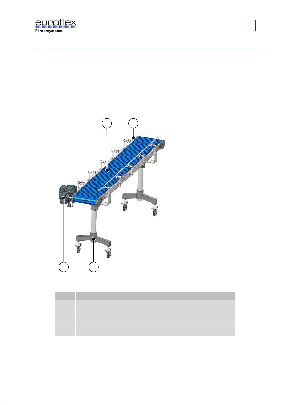
3.1 Overview of MB-flex O stainless steel.................................................................................... 9
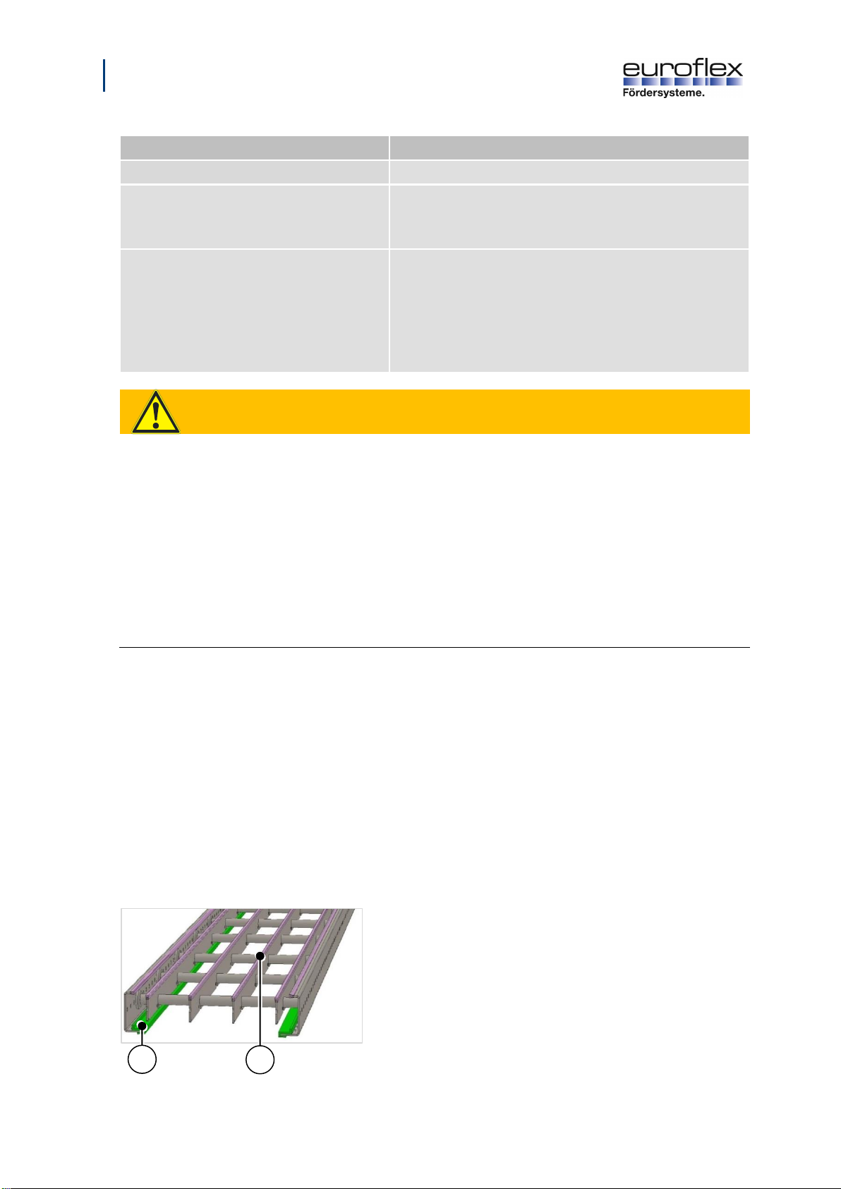
3.2 Assembly the chain guide profiles and slide profiles on the modular belt conveyor ............10
3.2.1 Assembly the chain guide profiles onto the bottom chassis profiles ...................... 11
3.2.2 Assembly the slide profiles on the modular belt conveyor......................................12
3.3 Assembling the modular chain belt.......................................................................................14
4Cleaning.................................................................................................................15
4.1 Personnel and Protective equipment....................................................................................15
4.2 Selection of the cleaning agent.............................................................................................15
4.3 Preparation ...........................................................................................................................16
4.4 Execution ..............................................................................................................................16
5Maintenance ..........................................................................................................17
5.1 Lubrication ............................................................................................................................17
5.2 Maintenance plan..................................................................................................................18
5.3 Maintenance log....................................................................................................................20
5.4 Repair ...................................................................................................................................20
5.4.1 Conveyor chain: Repair or adjust the chain tension...............................................21
6Table of figures .....................................................................................................23

Reader information
4
Quick installation guide_Conveyor system MB-flex Q N_20221114_EN.docx
1 Reader information
This chapter provides information on the usage of the installation guide:
▪Target group (Page 4)
▪Customer service (Page 4)
▪Copyright protection (Page 4)
1.1 Target group
This installation guide is intended for the owner, operators and the service personnel.
Info
The relevant personnel must have specific qualifications in order to work on or
with the system. The personnel qualification can be found in the section
„Qualification requirements“ (Page 6).
1.2 Customer service
Our customer service department will be happy to advise you on technical matters. Information on
ordering spare parts can be found in the section “Spare parts and their purchase”(Page 8).
Customer service
Designation
Specification
Company
euroflex GmbH
Street no.
Hohe-Flum-Straße 62
Postcode, place
79650 Schopfheim
Country
Germany
Telephone
+49 (0) 7622/68453-30
Fax
+49 (0) 7622/68453-01
Email
1.3 Copyright protection
This installation guide is protected by copyright.
The unauthorized forwarding of the installation guide to third parties, reproduction in any type and
form, including extracts, as well as the utilization and/or communication of the content are not
permitted without the written approval of the manufacturer.
Infringement will lead to compensation for damages. Rights reserved for further claims.

Safety
5
Quick installation guide_Conveyor system MB-flex Q N_20221114_EN.docx
2 Safety
This chapter provides information on the safe operation of the conveyor system:
▪Owner (Page 5)
▪Obligations of the owner (Page 5)
▪Instruction of the personnel (Page 6)
▪Qualification requirements (Page 6)
▪Personal protective equipment (Page 7)
▪Protective enclosure/Protective cover (Page 7)
▪Spare parts and their purchase (Page 8)
2.1 Owner
The owner is every natural and legal person that uses the conveyor system or permits it to be used
by third parties, and who is also responsible for the safety of the user, personnel or third party
during usage.
The owner is responsible for the correct assembly and accident-free operation of the system, in
accordance with the Machinery Directive 2006/42/EC.
For all work on the conveyor system, the safety regulations resulting from the specifications of the
Machinery Directive 2006/42/EC must be implemented and complied with.
2.2 Obligations of the owner
The owner is obliged to implement measures that result from the specifications provided by the
Machinery Directive 2006/42/EC.
The safety, accident prevention and environmental protection regulations valid for the conveyor
system's area of application must be complied with.
The owner is obliged to do the following in particular:
▪Provide information regarding the applicable occupational safety provisions and, via a risk
assessment, determine additional dangers that may result due to the special working
conditions at the conveyor system's deployment site. He must implement this in the form of
operating instructions for the operation of the conveyor system.
▪Regularly check the operating instructions and ensure that they correspond to the current
status of the regulations.
▪Instruct the utilized personnel on possible dangers and the corresponding protective
measures. These instructions should be repeated at appropriate intervals.
▪Instruct the utilized personnel on handling the conveyor system.
▪Equip the utilized personnel with the required protective equipment and check that it is worn at
all times.

6
Safety
Quick installation guide_Conveyor system MB-flex Q N_20221114_EN.docx
2.3 Instruction of the personnel
Each person assigned to carry out work must, before commencing, receive instruction from the
owner regarding their delegated activities and potential dangers during work.
For instruction, observe the following:
▪Repeat instruction at regular intervals.
▪Verifiably log each personnel instruction session.
2.4 Qualification requirements
Safety note: Risk of injury due to insufficient qualification.
If the conveyor system is used improperly, property damage may occur, or persons may be injured
or killed.
» All activities may only be carried out by personnel who have the required training,
understanding regarding the functioning of the conveyor system and the relevant experience.
Furthermore, special qualifications are required for certain tasks. These are defined as follows.
2.4.1 Specially trained personnel
Specially trained personnel are persons who have been instructed on the tasks delegated to them
and their potential dangers by the owner.
2.4.2 Operating personnel
Operating personnel are persons who have been instructed on the tasks delegated to them and their
potential dangers by the owner. The operating personnel are capable of operating the conveyor
system independently. The operating personnel have been instructed regarding possible dangers in
the event of improper behaviour. Cleaning and control tasks on the conveyor system are carried out
independently.
2.4.3 Maintenance personnel
Maintenance personnel are persons who, as a result of their technical training (e. g. mechanical,
electrical, pneumatic), knowledge, experience and awareness of pertinent norms and provisions, are
capable of correctly carrying out their delegated tasks. Maintenance personnel are capable of
recognizing potential dangers independently, and consequently avoiding them.
2.4.4 Qualified specialist personnel
Qualified specialist personnel are persons who have obtained and proven special experience,
knowledge and skills for the safe performance of tasks in particular specialist areas (e. g.
mechanical, pneumatic, hydraulic, electrical) and who fulfil the following defined requirements.

Safety
7
Quick installation guide_Conveyor system MB-flex Q N_20221114_EN.docx
2.4.5 Electricians
Electricians are persons who, as a result of their technical training, knowledge, experience and
awareness of pertinent norms and provisions, are capable of correctly carrying out work on electrical
systems. Electricians are capable of recognizing potential dangers independently, and consequently
avoiding personal injury and property damage caused by electrical currents.
All work on the electrical equipment may only be carried out by electricians.
2.4.6 Specialist pneumatic personnel
Specialist pneumatic personnel are persons who, as a result of their technical training, knowledge,
experience and awareness of pertinent norms and provisions, are capable of correctly carrying out
work on pneumatic systems. Specialist pneumatics personnel are capable of recognizing potential
dangers independently, and consequently avoiding personal injury and property damage caused by
pneumatic systems.
All work on pneumatic equipment may only be carried out by specialist pneumatic personnel.
2.4.7 Specialist hydraulic personnel
Specialist hydraulic personnel are persons who, as a result of their technical training, knowledge,
experience and awareness of pertinent norms and provisions, are capable of correctly carrying out
work on hydraulic systems. Specialist hydraulic personnel are capable of recognizing potential
dangers independently, and consequently avoiding personal injury and property damage caused by
hydraulic systems.
All work on hydraulic equipment may only be carried out by specialist hydraulic personnel.
2.5 Personal protective equipment
Wearing personal protective equipment is an important element of safety. Missing or unsuitable
personal protective equipment increases the risk of health damage and personal injury.
2.6 Protective enclosure/Protective cover
The conveyor system must be equipped with a protective enclosure/cover in areas where there is a
danger to persons. The protective enclosure/cover protects the operator and other persons from
injuries caused by danger points inside the enclosure/cover.
The owner is responsible for equipping the system with a protective enclosure/cover.

8
Safety
Quick installation guide_Conveyor system MB-flex Q N_20221114_EN.docx
2.7 Spare parts and their purchase
Spare parts and accessories can be ordered directly from the manufacturer via the following contact.
Spare parts: Contact
Designation
Specification
Company
euroflex GmbH
Street no.
Hohe-Flum-Straße 62
Postcode, place
79650 Schopfheim
Country
Germany
Telephone
+49 (0) 7622/68453-00
Fax
+49 (0) 7622/68453-01
Email

Assembly
9
Quick installation guide_Conveyor system MB-flex Q N_20221114_EN.docx
3 Assembly
This chapter provides information on the assembly of the conveyor system:
▪Overview of MB-flex O stainless steel (Page 9)
▪Assembly the chain guide profiles and slide profiles on the modular belt conveyor (Page 10)
▪Assembling the modular chain belt (Page 14)
3.1 Overview of MB-flex O stainless steel
Fig. 1: Overview of MB-flex O stainless steel (example)
Legend
No.
Designation
1
Modular chain belt
2
Side guide
3
Support
4
Motor
1
4
2
3

10
Assembly
Quick installation guide_Conveyor system MB-flex Q N_20221114_EN.docx
Information
Data
Designation or value
Personnel
Maintenance personnel
Personal protective equipment
Protective work clothing
Protective gloves
Safety shoes
Tools, aids
Mitre cutter
Steel pin (Ø 4 mm x approx. 200 mm long)
Hammer
Plastic mallet
Carpet knife
Drill and drill bit Ø 3.4 mm
WARNING
Risk of injury and serious damage to property due to improper installation!
A lack of knowledge about the system and experience in assessing and averting residual risks
during proper assembly can result in injury and even death.
» Before working on the system, turn it off and guard it from being switched back on.
» Prior to working in the system area, empty or clear the system.
» Regularly remove product residues and splitters from the entire system area.
» Check that the screw connections on all load-bearing and moving parts are tightened correctly
» Check correct function of bearings and links.
» Check the function of the safety devices.
» Wear appropriate personal protective gear in the system area.
Prerequisite:
▪System is switched off and safeguarded against being restarted.
3.2 Assembly the chain guide profiles and slide profiles on the
modular belt conveyor
Observe the following during assembly:
▪During assembly, align the butt joints of the components.
▪Avoid steps between the butt joints.
1. Fit the chain guide profiles (1) onto the bottom of
the chassis profiles as shown.
2. Fit the slide profiles (2) onto the top of the holding
profiles.
Fig. 2: Assembly the chain guide profiles and slide profiles on the modular belt conveyor
1
2

Assembly
11
Quick installation guide_Conveyor system MB-flex Q N_20221114_EN.docx
3.2.1 Assembly the chain guide profiles onto the bottom chassis profiles
1. Fit the chain guide profiles (1) onto the bottom of
the chassis profiles as shown.
2. Press the chain guide profile onto the chassis profile
in running direction as far as the stop with the bead
downwards (as shown).
ǃAvoid the development of “waves” in the chain
guide profiles by pressing it on completely
3. Check the chain guide profiles for damage.
ǃOnly use undamaged chain guide profiles.
4. Chamfer the chain guide profiles at the start (viewed
in running direction).
5. Mount the chain guide profile seams with a gap of
approx. 2 mm and offset.
ǃAlways mount the chain guide profiles over the
seams of the chassis profile.
6. Cut the chain guide profiles parallel in the running
direction.
7. Gently deburr the butt ends.
8. Each profile piece must be fixed at the beginning
(viewed in running direction).
9. Using the drill (drill bit ø 3.4 mm), drill a hole in the
chain guide profile and chassis profile.
10. Carefully knock in M4 x 8 plastic screw.
ǃSecure the chassis profile with a support against
bending!
11. Deburr after drilling.
12. Remove all chips.
13. Before intermediate elements or subsequent
elements, mount the chain guide profile flush with
the end of the chassis profile (viewed in running
direction).
14. At the end of the conveyor, mount the chain guide
profile flush with the drive.
Fig. 3: Assembly of the chain guide profiles onto the bottom chassis profiles
1
1

12
Assembly
Quick installation guide_Conveyor system MB-flex Q N_20221114_EN.docx
3.2.2 Assembly the slide profiles on the modular belt conveyor
1. Fit the slide profiles (2) onto the top of the holding
profiles.
2. Check the slide profiles for damage.
ǃOnly use undamaged slide profiles.
3. Chamfer the slide profiles at the start (viewed in
running direction).
4. Press the slide profiles in the running direction as
far as the stop.
ǃAvoid the development of “waves” in the slide
profiles by pressing it on completely.
5. Press the slide profiles at both ends onto the
chassis profile.
6. Press the slide profiles onto the holding profiles as
follows:
a) With straight holding profiles, press the slide
profiles onto the top side.
b) With bent holding profiles (in sliding bends),
press the slide profiles onto the top and bottom
side of the holding profiles.
7. Mount the slide profile seams with a gap of
approx. 2 mm and offset.
8. Cut the slide profiles at an angle in the running
direction.
9. Gently deburr the butt ends.
ǃAlways mount the slide profiles over the seams
of the holding profile.
10. Cut the slide profile straight at the end of the holding
profile ( viewed in running direction) and press it on
flush.
11. Gently deburr the butt ends.
2

Assembly
13
Quick installation guide_Conveyor system MB-flex Q N_20221114_EN.docx
12. Each slide profile piece must be fixed at the
beginning (viewed in running direction).
13. Using the drill (drill bit ø 3.4 mm), drill a hole in the
slide profile and holding profile.
ǃSecure the profile with a support against
bending!
14. After drilling, deburr and remove all chips.
15. Carefully knock in M4 x 8 plastic screw.
ǃSecure the profile with a support against
bending!
16. With holding profiles where the conveyor chain lies
on (chain running surfaces), cut the screw head
carefully and flush.
17. Rework possible supernatants with the file.
18. With chassis profiles, also cut the screw head
carefully from below (chain running surface) and
flush.
19. Rework possible supernatants with the file.
20. Before intermediate elements or subsequent
elements, mount the slide profile flush with the end
of the holding profile (viewed in running direction).
21. At the end of the conveyor, mount the slide profile
flush with the drive.
Fig. 4: Assembly the slide profiles on the modular belt conveyor

14
Assembly
Quick installation guide_Conveyor system MB-flex Q N_20221114_EN.docx
3.3 Assembling the modular chain belt
Observe the following during assembly:
▪Select the chain length so that the contraction of the chain ends is done with little effort.
ǃWith a tight chain, rattling will be heard at the drive station.
1. Check the run using a short piece of the chain.
2. Remove any clamping points and rework seams if
necessary.
3. Insert the chain centrally into the deflection and
push/pull until the chain has been completely pulled
through the conveyor.
4. To ensure that the sprockets engage exactly with
the chain, mount the sprockets in the same position
as the recesses in the chain.
5. Join the chain ends together.
6. Insert the connecting rod (1) (locking bead last) and
knock it in carefully.
Fig. 5: Assembling the modular chain belt
1

Cleaning
15
Quick installation guide_Conveyor system MB-flex Q N_20221114_EN.docx
4 Cleaning
This chapter provides information on the execution of the operating mode Cleaning:
▪Personnel and Protective equipment (Page 15)
▪Selection of the cleaning agent (Page 15)
▪Preparation (Page 16)
▪Execution (Page 16)
ATTENTION
Warning of material damage due to improper cleaning!
Improper cleaning leads to damage to the system or its surroundings.
» Cleaning the system according to the instructions in this installation guide.
» Do not use steam jet or high-pressure cleaning devices for cleaning surfaces.
» Do not use compressed air for cleaning and drying surfaces.
4.1 Personnel and Protective equipment
Personnel and Protective equipment
Specification
Designation
Personnel
Operating personnel
Personal protective equipment
Protective equipment against the cleaning agents used
according to the instructions of the manufacturer of the
cleaning agents
4.2 Selection of the cleaning agent
The cleaning agents used are specified by the local hygiene officer.
Observe the cleaning agent manufacturer's instructions.
Furthermore, observe the following:
Find application:
▪Solutions with a pH value between 4.5 and 9
▪Water under low pressure
▪Water with temperatures below 40°C
Find no application:
▪Cleaning products containing chlorine, ammoniac, phosphoric acid or their compounds
▪Abrasive cleaning products
▪Solutions with a pH value below 4.5 or above 9
▪Water under high pressure
▪Water with temperatures above 40°C

16
Cleaning
Quick installation guide_Conveyor system MB-flex Q N_20221114_EN.docx
4.3 Preparation
Carry out the following work steps:
1. Switch off the conveyor system.
▼No voltage is present at the conveyor system.
2. Close the pneumatic supply at the main valve and secure it with a personal padlock.
3. Secure the main switch on the control cabinet with a personal padlock.
The conveyor system is prepared for cleaning.
✓Ready.
4.4 Execution
Prerequisite:
▪Conveyor system is switched off and secured against being switched on again
▪Conveyor system is prepared for cleaning
Carry out the following work steps:
1. Remove residues of conveyance goods.
2. Remove contamination without damaging the surface.
3. Remove contamination with cleaning agents.
4. Rinse off solution with water under low pressure.
5. Rub surface to dry it.
✓Ready.
Contact euroflex GmbH for instructions on cleaning any further contaminants.

Maintenance
17
Quick installation guide_Conveyor system MB-flex Q N_20221114_EN.docx
5 Maintenance
This chapter provides information on the maintenance work to be carried out:
▪Lubrication (Page 17)
▪Maintenance plan (Page 18)
▪Maintenance log (Page 20)
▪Repair (Page 20)
5.1 Lubrication
Incorrect or negligent use of hazardous substances may lead to serious environmental pollution.
Observe the following:
▪Apply lubricant evenly and sparingly at the specified points.
▪Carefully remove any escaping, used or excess lubricant.
▪Deal with solvents and cleaning agents in accordance with the manufacturer's safety data
sheet.
▪Dispose of all hazardous substances in accordance with the regional guidelines and
commission a specialist company if required.
Malfunctions and excessive levels of wear on individual components are likely to result from the use
of operating substances that cause significant pollution and/or that fail to comply with the stipulated
specification. Warranty claims that can be traced back to this content shall be rejected.
Observe the following:
▪Use operating substances with the specified purity class.
▪Check the state of the operating substance at regular intervals.
Lubrication schedule
No.
Designation
Name
Note
Interval [Bh]
Lubricant
1
Roller chain (Drive)
Spray!
Every time after cleaning!
170
Silicone spray
NSF H1
2
Drive station,
Deflection,
Sliding bend,
Bending wheel
Spray!
Every time after cleaning!
40
Silicone spray
NSF H1
3
Gear motor (Drive motor)
Details on lubrication and maintenance see manufacturer of the
gearmotor

18
Maintenance
Quick installation guide_Conveyor system MB-flex Q N_20221114_EN.docx
5.2 Maintenance plan
Regular maintenance and care are required for the operational safety and fault-free operation of the
system. The specifications in the maintenance plan are guide values and must be adjusted by the
owner depending on the operating conditions.
ATTENTION
Warning of material damage due to non-original spare parts!
Use of non-original spare parts can lead to defects in the conveyance goods, operational
malfunctions, loss of safety functions and damage to or destruction of components.
» Only replace components with original spare parts from euroflex GmbH.
General
Assembly and maintenance work
Interval [Bh]
Personnel
Inspect the conveyor system for visible damage, noise
and vibration
8 (per shift)
Operating personnel
Check safety and protective devices for completeness
and function
8 (per shift)
Operating personnel
Replace defective equipment
Replace if required
Maintenance personnel
Check functionality of the operating and display elements
(buttons, switches, indicator lamps, manometers)
24 (daily)
Operating personnel
Replace defective operating and display elements
Replace if required
Maintenance personnel
Check legibility and completeness of signage
24 (daily)
Operating personnel
Clean or replace signage, if required
Clean or replace if
required
Operating personnel
Check fixing elements, retighten if required
1,000 (quarterly)
Maintenance personnel
Check the supply lines and connections for leakage
after the first 20
Maintenance personnel
24 (daily)
Maintenance personnel
Check the electrical connections for damage and firm
seating
24 (daily)
Electricians
Replace defective electrical connections
Replace if required
Electricians
Adhere to lubrication schedule
“Lubrication schedule”
(Page 17)
Maintenance personnel
Clean conveyor system
24 (daily)
Operating personnel

Maintenance
19
Quick installation guide_Conveyor system MB-flex Q N_20221114_EN.docx
Conveyor system
Assembly and maintenance work
Interval [Bh]
Personnel
Remove foreign bodies
8 (per shift)
Operating personnel
Clean conveyor system surface
8 (per shift)
Operating personnel
Check gear unit for leakage
8 (per shift)
Maintenance personnel
Inspect surface for damage
170
Maintenance personnel
Conveyor chain
check for damage and elongation
50
250
500
Maintenance personnel
thereafter every 500
replace
4,000
Slide profiles
check for damage and wear
50
250
500
Maintenance personnel
thereafter every 500
replace
4,000
Check all connections
Check bending wheel for damage and wear
500
Maintenance personnel
Check sliding bend for damage and wear
500
Maintenance personnel
Check roller transition/end module for damage and wear
500
Maintenance personnel
Flange bearing: Check eccentric ring for secure seating
170
Maintenance personnel
Check motor plate for secure seating
500
Maintenance personnel
Check bearing and links for correct function
1,000 (quarterly)
Maintenance personnel
Check toothed wheel for damage and wear
50
250
500
Maintenance personnel
thereafter every 500
Drive/Deflection unit
Assembly and maintenance work
Interval [Bh]
Personnel
Guides of the
conveyor chain
(KU side parts)
check for damage and wear
1,000 (quarterly)
Maintenance personnel
replace
7,000
Sprocket wheel/
Deflection pulley
check for damage and wear
1,000 (quarterly)
Maintenance personnel
replace
7,000
Ball bearing
replace
7,000
Maintenance personnel
Sheet metal flange
bearing
replace
7,000
Maintenance personnel
Roller chain at the
drive station
check for damage and wear
50
250
500
Maintenance personnel
thereafter every 500
Sprocket wheel on
roller chain
check for damage and wear
1,000 (quarterly)
Maintenance personnel
replace
Replace if required

20
Maintenance
Quick installation guide_Conveyor system MB-flex Q N_20221114_EN.docx
Electrical system
Assembly and maintenance work
Interval [Bh]
Personnel
Check electrical wiring for visible damage
40
Electricians
Electrical connections and distributors:
Check terminal boxes for damage
170
Electricians
5.3 Maintenance log
The required maintenance intervals are dependent on the intensity of use of the system at the
owner's deployment site and the consequent signs of wear. In order to be able to adjust the
maintenance intervals of these terms of use, the general condition of the system as a whole as well
as the assemblies and components must be logged in detail during the regular and (if required)
unscheduled maintenance work.
Observe the following when creating maintenance logs:
▪Produce a maintenance log for each maintenance task and log all performed maintenance
work.
▪Store the maintenance logs.
5.4 Repair
Incorrect repair work impairs the operational safety. This can cause accidents and seriously injure
people as a result.
Observe the following:
▪Repair work may only be carried out by the manufacturer or authorized specialist personnel.
▪Switch off the system and secure it against being switched back on before all repair work.
▪Switch off the compressed air system and secure it against being switched back on.
Depressurize the compressed air-conveying components. Check if the pneumatic system has
been relieved of pressure.
▪Work on the electrical system may only be carried out by trained electricians.
▪For all work on the electrical system, switch off the voltage supply and secure it against being
switched back on again by accident.
▪Only use original spare parts.
In case of repairs at the conveyor system, the customer service will help (see page 4: Customer
service).
Spare parts can be ordered directly from the manufacturer (see page 8: Spare parts and their
purchase).
Personnel
Specification
Designation
Personnel
Maintenance personnel
This manual suits for next models
1
Table of contents
Other Euroflex Accessories manuals
Popular Accessories manuals by other brands

Matsing
Matsing MS-MBA-4.2-H2-L2 instruction manual

Intermatic
Intermatic HB61R supplementary guide

Maxxima
Maxxima MEW-OS100LNW installation instructions

Weir
Weir Synertrex S3-Gen1 installation guide

IFM
IFM Efector 200 O5PG operating instructions

PCB Piezotronics
PCB Piezotronics 357C10 Installation and operating manual

Briggs & Stratton
Briggs & Stratton 1695196 installation instructions

HB Products
HB Products HBX Installation and configuration guide

IBM
IBM 15-inch Flat Panel Monitor Speaker Bezel user guide

Daikin
Daikin FWTSKA Installation and operation

Velleman
Velleman PEM7DBI manual

Hama
Hama MS-200 Operating instruction