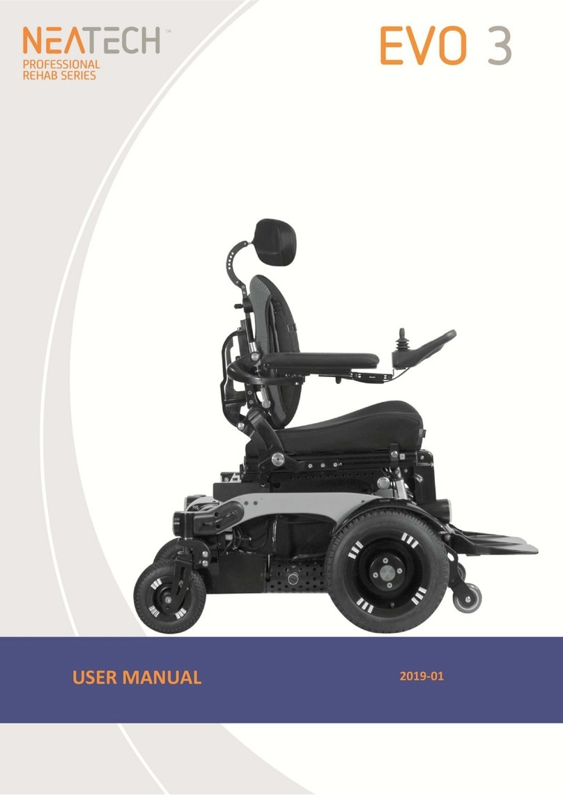
Eurogreen SupaChair COMBI SP Series User manual

COMBI 18SP / 20SP
User Manual
You must read this manual before using your Power chair
MDSS GmbH
Schiffgraben 41
30175 Hannover, Germany
COMBI SP
Distributor:
P/N: 9013925SP Rev. 01/20

Table of contents
SAVE THIS MANUAL FOR FUTURE REFERENCE.
- 1 -
INTENDED USE
Intended use of device
The device is a powered wheelchair intended to provide mobility to
persons restricted to a sitting position.
As a portable electric wheelchair for indoor or outdoor use.
Suitable for people with health related issues or walking difficulties.
Device description
A Hybrid rear wheel drive lightweight portable electric wheelchair.
This product has been designed to be completely portable but still
retain the characteristics of non portable electric wheelchairs.
Disassembly without tools for transport is quick and easy.
Technological characteristics
The Supachair Combi series has been designed to overcome the
heavy component weights associated with portable electric power
chairs without compromising performance or functionality. This has
been achieved with smaller high efficiency motors, lightweight
gearboxes, smaller batteries and lightweight materials. Quick dis-
assembly without tools allows for easy transport in smaller vehicles.
- 2 -
Contents Pages
Intended use- - - - - - - - - - - - -- - - - - - - - - - - - - - - - - - - - - -2
Safety Symbols, Words and Labels- - - - - - - - - - - - - - - - - - -3
Safety Instructions - - - - - - - - - - - - - - - - - - - - - - - - - - -4
Electromagnetic Interference - - - - - - - - - - - - - - - - - - - - - - -8
Assembly of the COMBI Wheelchair - - - - - - - -- - - - - - - - - -11
Drive Wheel Release Mechanism- - - - - - - - - - - - - - - - - - - -20
Detachable Footboard (Optional) - - - - - - - - - - - - - - - - - - - 21
Luggage Frame (Optional) - - - - - - - - - - - - - - - - - - - - - -22
Attendant Control (Optional)- - - - - - - - - - - - - - - - - - - - - - - 23
Self-Propelled Wheels (Optional) - - - - - - - - - - - - - - - - - - - 24
The Joystick Control - - - - - - - - - - - - - - - - - - - - - -- - - - - - -25
Fold the Wheelchair - - - - - - - - - - - - - - - - - - - - - - - -32
Precaution - - - - - - - - - - - - - - - - - - - - - - - - - - - - - - - - - - - 38
Battery and Charge- - - - - - - - - - - - - - - - - - - - - - - - - - - - - 39
Battery Charger- - - - - - - - - - - - - - - - - - - - - - - - - - - - - - 41
Battery Care & Maintenance - - - - - - - - - - - - - - - - - - - - - - 42
Specifications - - - - - - - - - - - - - - - - - - - - - - - - - - - - - - - - 43
SupaChair Warranty- - - - - - - - - - - - - - - - - - - - - - - - - - - - 45
Purchaser information - - - - - - - - - - - - - - - - - - - - - - - - - - 46
Manufacturer: EUROGREEN INTERNATIONAL INC.
No.48, Ln. 220, Sec.1, Fuzun Rd, Yuanlin
Township, Changhua County, 51055, TAIWAN

SAFETY SYMBOLS, WORDS AND LABELS
What You Need to Know About Safety Instructions
Warning and Important Safety Instructions appeared in this manual
are not meant to cover all possible conditions and situations that
may occur. Common sense, caution and care must be exercised
when operating or cleaning your Combi.
Always contact your dealer, distributor, service agent or
manufacturer about problems or conditions you do not understand.
This is the safety alert symbol. It is used to alert you
to potential personal injury hazards. Obey all safety
messages that follow this symbol to avoid possible
injury or death.
WARNING indicates a potentially hazardous
situation which, if not avoided, could result in
death or serious injury.
CAUTION indicates a potentially hazardous
situation which, if not avoided, may result in
minor or moderate injury.
Radio wave sources may affect motorized
vehicle.
- 3 –
SAFETY INSTRUCTIONS
●Please read this manual before using your Wheelchair.
●Check the frame lock and all clamps before using the wheelchair.
●The power switch should be “Off” when the user is entering or
leaving the chair.
●The Wheelchair was designed for the ground with hard and flat
surfaces. It should not be used on steep slopes or loose surfaces.
●Reduce speed when turning.
●Use of the wheelchair in wet conditions should be avoided when
possible.
●Do not use the Wheelchair on slopes over 8 degrees.
●Do not drive on slopes when the yellow battery light comes on.
Recharge your battery as soon as possible. If the red battery light
comes on or is flashing, you should stop immediately for recharging.
●Always switch the power “off” before leaving or while it is
unattended.
●Do not put your fingers on the joystick control lever before you turn
the key switch on. This could cause the Wheelchair to move without
warning.
●Your Power switch must be in the “off” position before connecting
the battery lead.
- 4 -

A. ENVIRONMENTAL CONDITIONS WARNING: The power chair is
not designed for use in a heavy rain storm, or in snowy or icy
conditions.
i. Contact with water or excessive moisture can cause an electrical
malfunction. The frame, motors and other power chair parts are
not water-tight and may rust or corrode from the inside.
To avoid a power chair failure:
●Minimize exposure of your power chair to a rain storm or very
wet conditions.
●Never take your power chair into a shower, tub, pool or sauna.
●Do not use your power chair in fresh or salt water (such as at
the edge of a stream, lake or ocean).
●Make sure all electrical connections are secure.
ii. Proceed slowly and use extra care if you must operate your
power chair on a wet or slick surface.
●Do so only if you are sure it is safe.
●Stop if one or both main wheels lose traction. If this occurs, you
may lose control of your power chair or fall.
●Never operate your power chair on a slope or ramp if there is
snow, ice, water or oil film present.
iii. When not in use, keep your power chair in a clean, dry place.
B. TERRAIN
i. This power chair is designed for use on firm, even surfaces
such as concrete, asphalt and indoor flooring.
ii. Do not operate your power chair in sand, loose soil or over
rough terrain. Doing so may damage wheels, bearings, axles or
motors, or loosen fasteners.
C. STREET USE WARNING: In most states, power chair are not
legal for use on public roads. Be alert to the danger of motor
vehicles on roads or in parking lots.
i. At night, or when it is hard to see, use reflective tape on your
power chair and clothing.
ii. It may be hard for drivers to see you. Make eye contact with
drivers before you proceed. When in doubt, yield until you are
sure it is safe. - 5 -
D. MOTOR VEHICLE SAFETY
i. Never sit in this power chair while in a moving vehicle. In an
accident or sudden stop you may be thrown from the power
chair.
ii. Always move to an approved vehicle seat. You must be secured
with proper motor vehicle restraints.
iii. Never transport this power chair in the front seat of a vehicle. It
may shift and interfere with the driver.
iv. Always secure this power chair so that it cannot roll or shift.
E. TRANSFERS WARNING: It is dangerous to transfer on your own.
It requires good balance and agility. Be aware that there is a point
during every transfer when the seat is not below you.
To avoid a fall:
i. Always turn off power before you transfer to or from your power
chair. If you fail to do so you may touch the joystick control lever
and cause your power chair to move when you do not expect it.
ii. Make sure power chair is turned “Off”. This keeps the power
chair from moving when you transfer.
iii. Move your power chair as close as you can to the seat you are
transferring to.
iv. Transfer as far back onto the seat surface as you can. This will
reduce the risk that you will miss the seat or fall.
F. REACHING OR LEANING WARNING: Reaching or leaning
affects the center of balance of your power chair. If done
improperly, a fall or tip-over is likely. When in doubt, ask for help or
use a power chair to extend your reach.
To reduce the risk of injury and/or damage to the power chair:
i. Never reach or lean if you must shift your weight sideways or
rise up off the seat.
ii. Never reach or lean if you must move forward in your seat to do
so. Always keep your buttocks in contact with the backrest.
iii. Never try to pick up an object from the floor by reaching down
between your knees.
iv. Never reach or lean over the top of the seat back. This may
damage the backrest and cause you to fall.
If you must reach or lean; do so at your own risk.
Remember to: - 6 -

i. Move your power chair as close as you can to the object you
wish to reach.
ii. Turn off all power to your power chair. If you fail to do so, you
may touch the throttle control lever and cause your power chair
to move when you do not expect it.
G. DRIVING IN REVERSE WARNING: Use extra care when you
drive your power chair in reverse. You may lose control or fall if
one of the rear wheels hits an object.
i. Operate your power chair slowly and at an even speed.
ii. Stop often and check to make sure your path is clear of
obstacles.
H. WEIGHT LIMIT
i. Never exceed the weight limit of the power chair.
ii. The power chair is not designed for weight training and is
unsafe for use as a seat while weight training. Weight training
from the power chair substantially changes the stability of the
power chair and may cause tipping.
iii. Exceeding the weight limit is likely to damage the seat, frame or
fasteners and may cause severe injury to you or others from
power chair failure.
I. STAIRWAYS AND ESCALATORS WARNING:
The power chair is not designed to travel up or down stairs or
escalators. Always use an elevator. DO NOT use an escalator to
move the power chair between floors. Serious bodily injury may
occur. DO NOT attempt to move an occupied power chair
between floors using a stairway.
- 7 -
ELECTROMAGNETIC INTERFERENCE
It is very important that you read
this information regarding the possible effects of
Electromagnetic Interference on your Supachair.
This power chair has an immunity of 20 V/m which should protect it from
Electromagnetic Interference (EMI) from Radio Wave Sources. These EM
waves are invisible and their strength increases as one approaches the
source. All electrical conductors act as antennas to the EM signals and to
varying degrees, all power wheelchairs and scooters are susceptible to
electromagnetic interference (EMI). This interference could result in
abnormal, unintentional movement and/or erratic control of the vehicle.
power chair may be susceptible to electromagnetic interference (EMI),
which is interfering electromagnetic energy (EM) emitted from sources such
a radio stations, TV stations, amateur radio (HAM) transmitters, two-way
radios, and cellular phones. The interference (from radio wave sources)
can cause the power chair to release its brakes, move by itself, or move in
unintended directions. It can also permanently damage the power chair
control system. The intensity of the interfering EM energy can be
measured in volts per meter (V/m). Each power chair can resist EMI up to
certain intensity. This is called its “immunity level.” The higher the immunity
level, the greater the protection. At this time, current technology is capable
of achieving at least a 20 V/m immunity level, which would provide useful
protection from the more common sources of radiated EMI.
Because EM energy rapidly becomes more intense as one moves closer to
the transmitting antenna (source), the EM fields from hand-held radio wave
sources (transceivers) are of special concern. It ispossible to unintentionally
bring high levels of EM energy very close to the power chair control system
while using these devices. Therefore, the warnings listed below are
recommendedto prevent possible interference with the control system of the
power chair, which should reduce the chance of unintended brake release
or power chair movement that could result in serious injury.
- 8 –

Do not operate hand-held personal communication
devices such as citizens band (CB) radios, or turn ON personal
communication devices and cellular phones while the power chair is
turned ON.
1) Be aware of nearby transmitters, such as radio or TV stations
and try to avoid coming close to them.
2) If unintended movement or brake release occurs, turn the
power chair OFF as soon as it is safe.
3) Be aware that adding accessories or components, or modifying
the power chair, may make it more susceptible to EMI; and
NOTE: There is no easy way to evaluate their effect on the
overall immunity of the power chair.
4) Report all incidents of unintended movement or brake release
to the distributor listed on the back of this manual, and Note
whether there is a radio wave source of EMI nearby.
TURN “OFF” YOUR POWER CHAIR AS SOON AS POSSIBLE
WHEN EXPERIENCING THE FOLLOWING:
‧ Unintended or uncontrollable movement.
‧ Unexpected brake release
- 9 –
●Important Information
1) 20 Volts per meter (V/m) is a generally achievable and useful
immunity level against interference from radio wave sources (as
of May 1994) (the higher the level, the greater the protection);
2) This product has an immunity level of following:
- 10 –

ASSEMBLY OF THE COMBI WHEELCHAIR
To assemble the Combi Wheelchair
Pull the two sides of wheelchair per illustration and press the side
tube “D” into the groove of “C”.
Open the backrest per illustration and insert the tube into the
corresponding hole and tighten the clamp G.
- 11 –
●Pull the frame locking
pins on both sides and
turn them anticlockwise
per illustration.
●Put the wheelchair
onto motorized frame,
with the guide pin in
the corresponding hole
on side plate of “A”.
- 12 -
Frame Locking Pin

●Push down on lever B to lift the motor upwards to the horizontal
position and hold it. Use the other hand to turn all 4 frame locking
pins clockwise and check that they lock into position. Lever B may
need pushing down firmly to allow all pins to be fully engaged.
●Both side lock pins must be securely in position.
- 13 -
Footrest assembly:
●Place the footrest holes “J1” and “J2” onto the the corresponding
pins of K1 & K2, then swing the footrest to the position per the
illustration.
●The height of footrest can be adjusted with the bolt “I”.
- 14 -

Armrest assembly:
●Insert armrest per the illustration. Push lever “O” to allow the
armrest into the slot and adjust the height as required.
- 15 -
●Insert cable connector P1into the corresponding hole of joystick.
●Insert the joystick “Q” into the corresponding axle, the groove Son
the axle must match to pin inside the joystick.
●Tighten clamp correctly and be sure that joystick is securely
mounted.
For SLA Battery
Install the battery into the tray and fasten it securely.
Tighten the battery strap as illustrated.
●Connect the battery plug ”Q” to the fixed plug on the frame.
●The battery lead connectors are color matched. Don’t try to force it
into the wrong position.
- 16 -

For Lithium Battery
●Pull the knob (Z) backward and
ha
ve 2 block (X) Insert into slots (B)
as illustrated direction then push
battery module downward until you
hear “click”, the locking into cam locker.
●You must check that the battery
module has locked into position.
●Plug the cable connector P2into the corresponding hole.
●The battery must be installed last and taken out first when
disassembling the drive mount.
●Inflate the tyres to a maximum of 40 PSI.
IT IS IMPORTANT THAT YOU TAKE EXTRA CARE TO PRACTICE IN
AN OPEN SPACE AWAY FROM OBSTRUCTIONS.
- 17 -
SWING AWAY THE JOYSTICK
●The joystick can be swung rearwards
by pulling the knob “R” rotating the
joystick back alongside the armrest.
BACKREST ANGLE ADJUSTABLE
●The backrest angle
can be adjusted by
unscrewing F1 and
pulling F2 out, then
insert by choosing
different angles for A1,
A2 or A3.
- 18 -

SWING AWAY THE ARMREST
●The armrest can be lifted up by pushing “W” and can be locked by
pressing down.
●Do not turn “on” until the user is seated and ready to go.
●Always turn the joystick “off” before getting off the power chair.
NOTE: Please be aware that should the power chair wheels hit an
obstruction, you may need to help it out manually. Attempting to drive
the power chair past an obstruction may result in damage.
●Do not put your hand on the joystick lever when switching “on” the
controller as this could cause the power chair to move without warning.
- 19 –
DRIVE WHEEL RELEASE MECHANISM
●This power chair is equipped with a drive wheel release
mechanism. Your power chair can be moved
manually after the drive wheels are released.
Do not operate this device on a slope.
To disengage the drive wheels
Pull the drive collar (part “A”) out and
turn it left or right, then release it.
To reconnect the drive wheels
Turn the drive collar (part “A”) until it reconnects with the wheel
and then move the power chair until the collar connects with the
drive. (a loud click)
- 20 -

DETACHABLE FOOTBOARD (OPTIONAL)
●Assemble the footboard per illustration.
- 21 –
LUGGAGE FRAME (OPTIONAL)
Assemble the luggage frame per illustration and tighten bolt “U”.
NOTE:
This luggage frame are NOT available for USA market.
- 22 –

ATTENDANT CONTROL (OPTIONAL)
Assemble the attendant control per illustration and plug the cable P2.
- 23 –
SELF-PROPELLED WHEEL (OPTIONAL)
●Assemble the 20” self-propelled wheel per following illustration.
(Axle position A1)
●Fit anti-tip device per illustration, you must essure that anti-tip
device have locked into position (A5 into A6).
NOTE:
This self-propelled wheels
for indoor use only and
NOT available for
USA market.
●Assembly the 24” self-propelled wheel per following illustration.
(Axle position A1)
●Fit anti-tip device per illustration, you must ensure that anti-tip
device have locked into position (A5 into A6).
- 24 –

THE JOYSTICK CONTROL
●Power up / down
In the unlikely event that the wheelchair is in a runaway situation, the
user can press the Remote's power button to perform an
EMERGENCY STOP.
To witch ON the Sy tem, pre the Power button.
The Power button i the only u er input that can
activate the y tem.
If there i no fault with the y tem, the Statu
indicator (through the Power button) will light up
green, and the Battery Gauge will di play the current
battery tatu .
Power OFF
If there i a fault with the y tem when powering up,
the tatu indicator will indicate the fault with a erie
of red fla he . If the fault i one that prevent the
y tem from driving, then the battery gauge will fla h
continuou ly.
- 25 –
To witch OFF the y tem, pre the Power button;
the y tem will power down and the Statu indicator
will witch off.
Power ON
The Power button i al o u ed to perform an
EMERGENCY STOP. The Power button i al o u ed to
lock the y tem.
●Emergency top
If the u er need to top the wheelchair quickly, the Power button
can be pre ed to perform an EMERGENCY STOP. The wheelchair
will come to a halt quickly; the rate i et by the Emergency
Deceleration parameter.
●Drive inhibit indication
Drive inhibit mode i indicated by the
battery gauge with a right-to-left cha e
equence.
The cha e equence tart with the green
LED on the right- hand ide, and one-by-
one, each LED will witch on and then off.
When the equence complete at the left-
mo t red LED, it begin again at the right-
hand ide.
The cha e equence continue until the
error condition ha been cleared.
●OONAPU
OONAPU (“Out Of Neutral At Power Up”) i a afety feature
that prevent accidental movement of the wheelchair, either
when powering up, or when the wheelchair come out of an
inhibit tate.
If the Sy tem i turned on (or come out of an inhibit tate) while
the joy tick i not in the center po ition, an OONAPU warning i
di played. During an OONAPU warning, the battery gauge LED
will fla h continually to alert the u er, and the chair will not drive.
If the joy tick i returned to the center po ition within five
econd , the warning will clear and the wheelchair will drive
normally.
- 26 –

However, if the joy tick remain out of neutral for longer than
five econd , an OONAPU error will occur; the error i di played
by the Statu indicator fla hing red, and the chair will not drive.
To clear the error, return the joy tick to the neutral po ition and
power the unit off and then on again.
●The joy tick
The joy tick control the direction and peed of
the wheelchair.
When the joy tick i deflected from the center
po ition, the wheelchair will move in the direction
of the joy tick movement.
The peed of the wheelchair i proportional to the
joy tick deflection, o that the further the
joy tick i moved from the center po ition, the
fa ter the wheelchair will travel.
The joy tick can al o be u ed to wake up the
y tem when in leep mode.
●Controlling maximum peed
The peed dial allow the u er to limit the maximum
peed of the wheelchair (that i , the peed when the
joy tick i fully deflected) to uit their preference and
environment.
The speed dial
The dial offer 10 di crete tep between the lowe t
peed (dial et to the left) and the highe t peed (dial
et to the right).
A a vi ual reminder, a peed ymbol ( hown left) i
po itioned ju t below the peed dial to indicate the
low and high po ition of the peed dial.
The speed symbol
●Stopping di tance
Practice riding in an open area free of vehicle , pede trian and
ob tacle before u ing your SupaChair, and learn for topping
di tance.
- 27 –
●The horn
Pre the Horn button to ound the horn. The horn will
ound for a long a the Horn button i pre ed.
The Horn button i al o u ed for unlocking a locked
y tem - ee below for more detail .
The horn button
●The lock function
The lock function i u ed, primarily, to re trict who can u e the
y tem, but al o can help prevent unintentional u e of the
control for when the y tem i not required for any length of
time.
When a y tem i locked ( ee below), the y tem i powered
down, and the u er control are not re pon ive. If the power
button i pre ed when the y tem i locked, the locked tatu i
di played to the u er by the Battery Gauge.
To unlock the y tem, an unlock equence mu t be performed
( ee below) by the u er within a pecific timeframe. If the
equence i not performed correctly, within the timeframe, the
y tem remain locked.
To lock the y tem, pre and hold the
Power button for 4 econd .
When entering the locked tate, the
battery gauge will indicate the tran ition
by fla hing LED 1, 3, and 5 (far left,
middle, and far right) 3 time .
Power OFF
To unlock the y tem, pre the Power
button once, and then, press the Horn
button twice — the Horn button mu t be
pre ed twice within 10 econd of
pre ing the Power button.
Power ON
If the u er implement the unlock equence incorrectly, or the
Power button i pre ed again before the unlock equence i
complete, the y tem will return to the locked tate.
- 28 –

During an unlock attempt, the battery gauge will indicate the y tem i
in a Locked tate by fla hing LED 1, 3, and 5 (far left, middle, and far
right) until either the y tem i powered off, unlocked, or the Sequence
Timeout i reached.
The lock function is only available when the
Enable Lock
parameter is set to
Yes
;
The horn will not sound when pressing the Horn button during the
unlocking sequence.
●The battery gauge
The battery gauge compri e five different LED
(1 x RED, 2 x AMBER, 2 x GREEN), ituated
above the Remote' Horn button. The number
of LED lit depend on the tatu of the
battery, a hown below.
The battery gauge LED are al o u ed to
di play charging information. See ection 7.2
Battery charging for more detail .
The battery gauge
Normal operation
Battery auge Battery Level Notes
Fully charged Thi level i et by the Battery
Gauge Maximum parameter.
Batt Gauge Maximum.
Con ider charging battery
Battery need charging Thi level i et by the
Battery Gauge Minimum
parameter.
Battery Gauge Minimum.
Battery gauge operation
This battery gauge is setting based on SLA battery, for lithium
battery will need to reprogram for meet with its voltage.
- 29 –
●High voltage warning
A high voltage warning i indicated by all LED on,
and the green LED fla hing. Thi occur when the
battery voltage level ha ri en above the high
voltage warning et-point.
High voltage warning
●Low voltage warning
A low voltage warning i indicated with the left-
mo t LED fla hing. Thi occur when the battery
voltage level ha decrea ed below it low voltage
warning et-point.
Low voltage warning
Charge the battery immediately - it i being damaged.
●Cut-off voltage
When the battery voltage decrea e below the battery cut-off
voltage:
l
the tatu indicator will fla h ( Fla h code 2)
l
the fir t (red) LED will fla h on the battery gauge
l
the horn will ound once every 10 econd
The tatu indicator
The tatu indicator i located underneath the power
button. When the Sy tem i not powered up, the tatu
indicator i not lit.
When the Sy tem i powered up, and there are no
fault with the y tem, the tatu indicator will be lit
green.
If, when powered up, there i a fault with the y tem,
then the tatu indicator will fla h red. The number of
fla he will indicate the type of error.
The status indicator
- 30 –

●
Error indication
The status
indicator
If there is an error with the system when it
is powered up,
then the status indicator will flash red; the number of
flashes will indicate the type of error.
The table below describes the error indication, and a few
possible actions that can be taken to rectify the problem.
The actions listed are not in any particular order and are
suggestions only; the intention is that one of the
suggestions may help you clear the problem. If in doubt,
consult your supplier.
Flash
code
Error description
Possible action
1
Remote / joystick heck cables and connectors Replace Remote
2
Network or
configuration error
heck cables and connectors
heck Bluetooth pairing
Reconfigure the system
Recharge the battery
heck charger
Replace modules
ontact supplier
3
Left motor error heck cables and connectors
Replace Power Module
heck and/or replace left motor
4
Right motor error
heck cables and connectors
Replace Power Module
heck and/or replace right motor
5
Left park brake error
heck cables and connectors
heck left park brake is released
6
Right park brake error
heck cables and connectors
heck right park brake is released
7
Module error (other
than Remote)
heck cables and connectors
heck modules
Replace Power Module
Recharge battery
If the chair stalled, reverse away or remove obstacles, or
if the chair was moved while turned off, cycle the power.
The error indicator may continue to fla h after an error ha been
rectified.
To clear the error indication, cycle the y tem' power.
- 31 –
FOLD THE WHEELCHAIR
●Unplug the battery connector Q, undo the strap and remove the
battery.
●The battery must be taken out first and installed last –when
assembling the drive mount.
For Lithium Battery
●Unplug the battery connector,
Pull knob backward and pull up
●Unplug the battery the battery handle for removing
connector, undo the strap lithium battery as illustrated.
and remove the SLA battery.
For SLA Battery
●Pull out the cable connector P2 as indicated. (Refer to P.33)
- 32 –

●Loosen clamp and pull out joystick.
●Pull out the cable from cable locker as arrow illustration.
●Push Sand remove the cable from the Joystick.
Don’t try to pull the cable without pushing S as this will cause the
Lock S to break.
- 33 –
●Push lever “O” and move the armrest.
●Turn the footrest outward direction and lift up for disassembly.
- 34 –

●Use one hand to push lever “B” and use the other hand to pull the
lock pin knobs on both sides and turn them clockwise.
●Use one foot to press the lever “B” and use both hands to hold the
handles of backrest to let guide pins released from side plates and
move the chair out of motor drive mount.
- 35 –
●Remove the backrest and fold per arrow direction as illustrated.
- 36 -

- 37 –
PRECAUTION
●When using your power chair for the first time you should
practice at slow speed in a flat open area free of obstacles,
until you are confident in turning, stopping, reversing and judging
braking distance.
●This power chair is designed for a maximum rider weight of
125kgs and for one person use only.
●Always switch power off (button switch to “Off” position) before
leaving your power chair.
●Do not store your power chair outside without adequate protection.
●Keep the shipping carton in dry place after unpacking your power
chair in case it needs shipping for service.
●This appliance is not intended for persons (including children)
with insufficiency of physical, sensory or mental capabilities, or
lack of experience and knowledge, unless they have been given
instructions concerning use of the appliance by a person
responsible for their safety. Children should be supervised to
ensure that they do not play with the appliance.
Your power chair is extremely maneuverable but sharp turns must
only be done at very slow speed.
Avoid power spray water washing of the power chair as this could
cause damage to the wire connectors and electronic system.
Completely dry off the power chair, if necessary using a dry cloth
after cleaning your power chair.
- 38 -
This manual suits for next models
2
Table of contents
