Eurolube 53408 User manual
English Manual for TCM-module 53408, R10, 181008
LUBE-MASTER R10
R10
TCM MANUAL
TANK CONTROL MODULE
53408

LUBE-MASTER R10
2(20)
Table of Contents
1. INTRODUCTION 3
2. MECHANICAL INSTALLATION 3
3. ELECTRIC INSTALLATION 3
4. CONFIGURATION 5
4.1. CHECK BEFORE CONFIGURATION 5
4.2. ADDRESSING THE TCM 5
4.3. SET-UP MODE 5
4.4. CHANGE ADDRESS [TCM//ADDRESS]5
4.5. RECOMMENDATION FOR SETTING ADDRESSES 6
5. CONFIGURE THE PORTS 6
5.1. CONNECT A TANK TO A PORT [TCM//PORTX/TANK]6
5.2. SET THE MASK [TCM//PORTX/MASK] 6
5.3. ANALOGUE SENSOR SETTINGS 7
5.3.1. Set the input signal filter time constant .............................................................................................7
5.3.2. Adjusting the offset ............................................................................................................................7
5.3.3. Adjusting the calibration ...................................................................................................................7
5.3.4. Set sensor full scale ...........................................................................................................................8
5.4. FLUID SPECIFICATION 8
5.4.1. Set fluid name....................................................................................................................................8
5.4.2. Set fluid part number.........................................................................................................................8
5.4.3. Set the fluid density............................................................................................................................9
5.5. TANK SPECIFICATION 9
5.5.1. Set tank capacity................................................................................................................................9
5.5.2. Set the tank reorder volume level ......................................................................................................9
5.5.1. Set the tank stop volume level..........................................................................................................10
5.5.2. Set tank bottom area........................................................................................................................10
5.5.3. To configure a TCM port for a tank that does not have a constant area.........................................10
5.6. DISPLAYING TANK CONTENT ON A LED DISPLAY 11
5.6.1. Set LED address ..............................................................................................................................11
5.6.2. Set LED update interval ..................................................................................................................11
5.7. SET THE TYPE OF TANK (PC SYSTEM). 12
6. MENU TREE 13
7. FAST MENU CODES 14
8. TECHNICAL SPECIFICATION 15
9. TO CONNECT DISCRETE LEVEL SENSORS 53132/138/171 AND SOLENOID VALVES 16
9.1. FRESH OIL TANK,53138 (2-LEVELS) 16
9.2. FRESH OIL TANK,53171/53183 (1-LEVEL) 16
9.3. WASTE OIL TANK,53132 (2-LEVELS) 16
9.4. ONE TCM PORT CONTROLS A NUMBER OF PUMPS 17
10. EX-BARRIER 53187 FOR DISCRETE LEVEL SENSORS. 17
10.1. CONNECTING A WASTE OIL TANK 53132 (2-LEVELS) 18
11. TO CONNECT AN ANALOGUE SENSOR 18
11.1. ANALOGUE SENSOR 53417 18
11.2. CONNECTING AN ANALOGUE SENSOR. 19
12. EX-BARRIER 53188 FOR ANALOGUE SENSORS. 19
12.1. CONNECTION 20
13. MPDM PCB MOUNTED IN A TCM BOX 20

LUBE-MASTER R10
3(20)
1. Introduction
The LUBE-Master TCM module, (Tank Control Module), is used to control pumps and/or measure levels in tanks
using floater based level switches. A TCM can be used both for fresh and waste oil tanks.
The TCM (53408) is eighter a MPDM (53400) with another software (early model the chip should be labeled TCM
1.xx.xx) or has the PCB 203 02 91 equipped with a chip marked TCM 2.xx.xx.. Because of this a lot of this manual is
similar to the manual of the MPDM.
NOTE! The LUBE-Master installation guide should be available when installing and configuring a TCM.
2. Mechanical installation
The TCM is delivered mounted in a metal box with power supply. It can also be delivered as a PCB with mounting kit.
Complete TCM in a box is mounted on a wall or other suitable place using the four-ø5 mm holes in the bottom corners
of the box.
If a PCB is used it is important that a power supply with enough performance is used.
3. Electric installation
The power supply should be connected to mains
230VAC in a proper way following valid rules.
Alentec & Orion AB recommends that the
connection be done through a 2-pole working
switch.
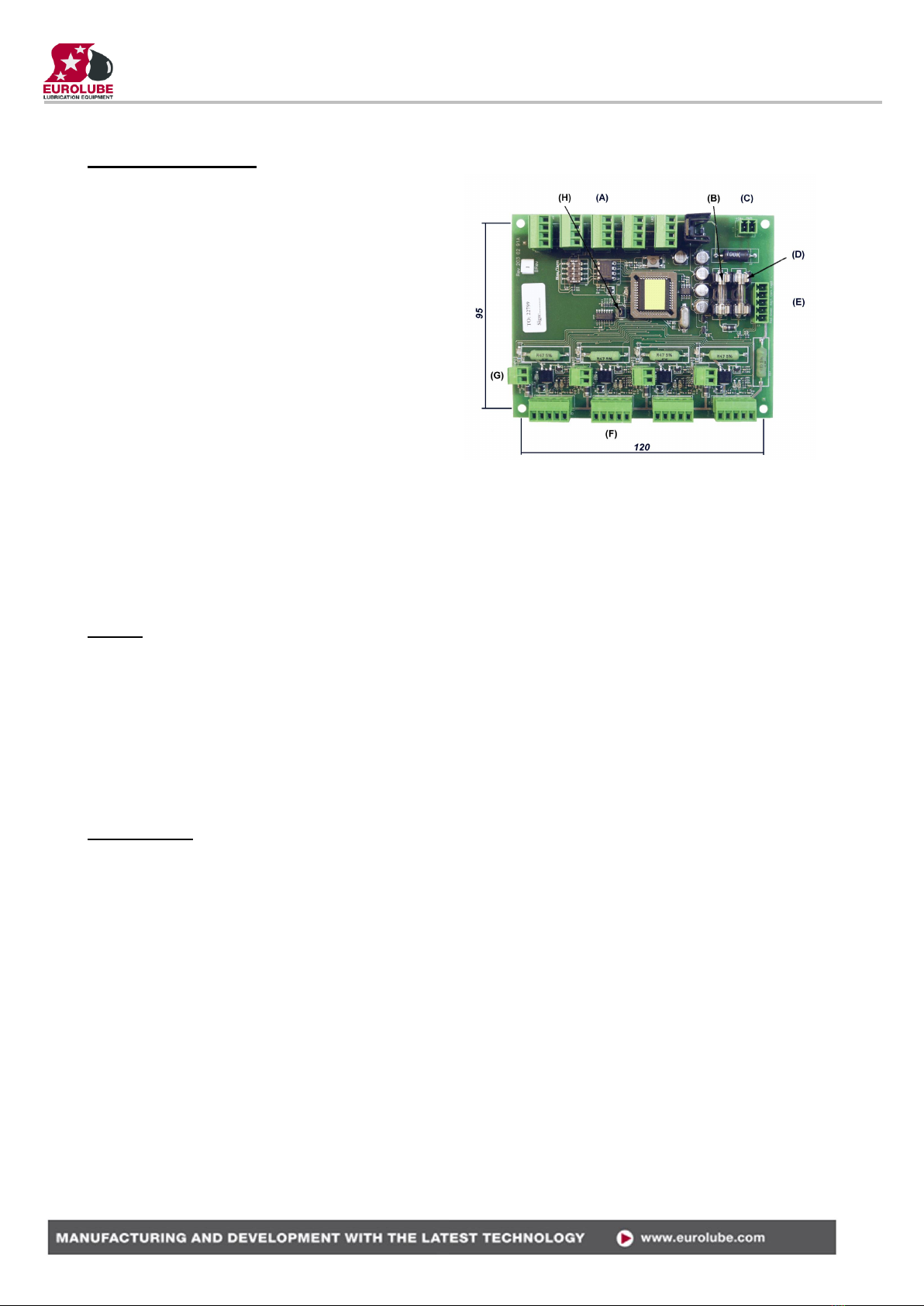
It has five connectors (A) for the LUBE-Master communication. Two of these connectors, MPDM IN and MPDM
OUT are not connected to +24V and are intended for a connection to another TCM, MPDM or other modules that
already have +24VDC. This is to prevent connecting +24VDC from two power supplies.
The other three connectors are used to connect external devices without a power source such as a Printer Module (PM),
a LED Module (LED) and/or a KeyPad (KP). These connectors can only supply power to a single device. For more
detailed information see the LUBE-Master Manual
NOTE! If the communication loop begin in one of these modules it must be connected to either MPDM IN or
MPDM OUT or +24V must not be connected.
The RESET-button (B) can be used to reset the module or reset the module address. Power supply is connected to the
connector (C).
NOTE! Check polarity, GND is closest to the hole!
The connector (D) is used when you install a chassis-mounted key switch and diode.
With the key switch you can set the status of the module to OFF-, NORMAL-, or
OVERRIDE-mode. The diodes indicate setting.
There are four connectors (E) market +24 V, OC, A, B and GND, one for
each pump/tank. Solenoid valves and level sensors are connected to these
connectors.
“A” of a TCM port is connected to “order oil/emptying” of the level
sensor.
“B” of a TCM port is connected to “Stop level” of the level sensor.
“GND” of a TCM port is connected to common of the level sensor.
“+24V” of a TCM port is connected to one of the terminals of a solenoid
valve and “Sol” is connected to the other.
TIP! If a TCM is used for a tank containing flammable liquid it could be necessary to use an EX
protection.
ALARM
Solenoid valve
STOP
+24 V
A
GND
B
Sol

LUBE-MASTER R10
4(20)
There are two diodes (F) for every port. These indicate the status of entry points A and B, the level in the tank.
One diode (G) on each port indicates if the solenoid valve is open or not.
If the diode (H) is flashing the module is operational and working properly. A steady light or completely off indicates a
problem.
DIL switches for termination and BIAS are located at (I). (J) Shows the position of the replaceable communication
driver. The SetupLock jumper at position (K) has no function for a TCM.
A LED (L) shows if an analogue sensor is detected or not, lit if detected. The analogue sensors are connected to the 2-
pole connectors marked (M). The polarity is marked on the PCB.
TCM100 PCB 203 02 62X with chip
TCM 1.xx.xx.
TCM200 PCB 203 02 91X with chip
TCM 2.xx.xx.

LUBE-MASTER R10
5(20)
Reel:SETUP ‡
EXIT STOP CE ENT
PASS:_ ‡
Enter Password
Addr:8???_ ‡
Address[CODE]
TCM: ‡
TCM MainMenu
TCM: ‡
TCM MainMenu
Address:8XXX ‡
Ange Adress 8???
Address:8XXX ‡
Set Address 8???
4. Configuration
An LUBE-Master configuration sheet should always be filled or altered during the configuration.
NOTE! To obtain technical support a copy of the configuration sheet for the complete installation must be
sent to Alentec & Orion AB at
E-mail: lubemaster@alentec.se
Post: Alentec & Orion AB
LUBE-Master Support Team
Grustagsvägen 4
SE-138 40 Älta
SWEDEN
4.1. Check before configuration
Check that the TCM is working and communicating with the system according to the LUBE-Master Manual chapter
Testing modules.
NOTE! Do not forget to check and adjust the termination and BIAS according to LUBE-Master Manual.
4.2. Addressing the TCM
A new module has a default address when delivered such as MPDM 1000, PM 2000, KP 3000, LED 4000, TCM
8000 and so on. To set an address for a new TCM or a TCM with unknown address press and hold it’s RESET
button for 5 seconds to set a temporary address. Immediately enter set-up mode from a KP and type 0 and then
ENTER to get to the Main menu of the TCM, see below.
NOTE! Only one new module can be installed at a time. If you press the RESET-button on several
terminals simultaneously or in a sequence, only the most recently pressed will be active.
TIP! Follow preferably ”Recommendation for setting new addresses” when setting addresses.
4.3. Set-Up mode
Type the word ”SETUP” on a KeyPad and press ENTER.
Type the password and press ENTER.
Type the address for the TCM that is to be configured and press ENTER to access
its main menu. It is possible to add the 4-digit menu code to go directly to the
desired menu.
Scroll through the TCM sub menus by pressing or . When the desired menu is
shown press ENTER etc.
4.4. Change address [TCM//Address]
Enter menu [TCM//Address] by pressing ENTER.
Press ENTER to get the cursor.
Type in the desired address and acknowledge by pressing ENTER. When the
cursor disappears it is finished.
Press EXIT two times to leave Set-Up mode.
NOTE! If two or more TCM’s have the same address the system will fail. The TCM’s has to be re-addressed.
TIP! Follow preferably ”Recommendation for setting addresses” when setting addresses.

LUBE-MASTER R10
6(20)
TCM: ‡
TCM MainMenu
PortX: ‡
TCM MainMenu
Mask:X ‡
Set Mask 0-15
Mask:X ‡
Set Mask 0-15
Mask:X ‡
Set Mask 0-15
TCM: ‡
TCM MainMenu
PortX: ‡
TCM MainMenu
Tank:X ‡
Set TankNo ???
Tank:X ‡
Set TankNo ???
4.5. Recommendation for setting addresses
Each module demands a unique 16 bit hexadecimal address. There are
some forbidden and some reserved addresses but it is possible to use all
addresses between 0001 and 9999. To make it easier to upgrade and
support the system we recommend using the chart to the right.
This means that the first TCM should have the address 8001 and the next
one 8002 etc. It is a good idea not to use the default address 8000, it
makes it easier to add new Tam’s
NOTE! It is essential to add modules to the configuration sheet
continuously as they are configured to avoid collisions.
NOTE! Address 0000 is forbidden and addresses above 9999 are
reserved for the system.
5. Configure the ports
A TCM has four ports that are used to control four different pumps/tanks.
5.1. Connect a tank to a port [TCM//PortX/Tank]
This is only needed for systems using the service TCmS.dll (early versions).
A R6 or later system uses the WinDb Service (WinDB.dll) for this and then
TankNo is only for informational purpose. Use correct TankNo or set all to “0”.
Enter menu [TCM//PortX] by scrolling with or .
At PortX: press ENTER.
Press ENTER to get the cursor.
Check the number of the tank that is connected to portX, type that number in and
press ENTER to acknowledge. When the cursor disappears it is finished.
Press EXIT two times to leave Set-Up mode.
5.2. Set the Mask [TCM//PortX/Mask]
Using the Mask each tank function can be set. This is done by
adding the values for the desired functions, in the chart to the right.
EXAMPLE: Port 1 measures the level of a waste oil tank and
controls the air to a waste oil pump using an Eurolube 2-levels
sensor 53132. This is up done by calculating the value of the Mask 1+4+8=13. The Mask should be set to 13.
Enter menu [TCM//PortX] by scrolling with or .
At PortX: press ENTER.
Scroll to Mask: using or .
Press ENTER to get the cursor.
Type the mask value and press ENTER to acknowledge. When the cursor
disappears it is finished.
Press EXIT two times to leave Set-Up mode.
Adress Module
0000 Forbidden
1000 –1xxx MPDM
2000 –2998 PM
2999 PC-database
3000 –3xxx KeyPad
4000 –4xxx LED-display
5000 –5xxx PLC-modules
6000 –6xxx Reserved
7000 –7xxx Reserved
8000 –8xxx TCM
9000 –9xxx Others
A000 –FFFF Forbidden
Function Value
Waste oil tank 1
Disable output 2
Invert B 4
Invert A 8
LUBE-MASTER R10
7(20)
TCM: ‡
TCM MainMenu
PortX: ‡
TCM MainMenu
O:0.000 ‡
Zero adjust
O:-0.120_ ‡
Zero adjust
O:-0.120 ‡
Zero adjust
TCM: ‡
TCM MainMenu
PortX: ‡
TCM MainMenu
C:1.000 ‡
Calibration
C:1.000 ‡
Calibration
C:1.000 ‡
Calibration
TCM: ‡
TCM MainMenu
PortX: ‡
TCM MainMenu
T:6 ‡
Time constant
T:6 ‡
Time constant
T:6 ‡
Time constant
5.3. Analogue sensor settings
5.3.1. Set the input signal filter time constant
This time constant (Tau) is used to filter the sensor signal to create an
accurate tank level. “0” means no filter and a higher value gives slower
response but a more accurate value. The default value of “6” is in most cases
good. It means that for a step in the tank level the reading of the level is on
99,9 % after 30 seconds.
Enter menu [TCM//PortX] by scrolling with or .
At PortX: press ENTER.
Scroll to T: using or .
Press ENTER to get the cursor.
Type the time constant and press ENTER to acknowledge. When the
cursor disappears it is finished.
Press EXIT two times to leave Set-Up mode.
5.3.2. Adjusting the offset
Offset adjusting is used to obtain “0” volume when the tank is empty. If the
sensor 23 417 is used a normal value is –0.080. The “-“ sign is typed on the
keypad by first pressing down arrow (yellow) two times followed by the “?”
mark.
If the tank is empty, put the sensor in the tank at the bottom. If there is fluid
in the tank hold the sensor outside the tank at bottom level. Adjust the offset
value until the tank level shows “0”.
Enter menu [TCM//PortX] by scrolling with or .
At PortX: press ENTER.
Scroll to O: using or .
Press ENTER to get the cursor.
Type the offset value and press ENTER to acknowledge. When the cursor
disappears it is finished.
Press EXIT two times to leave Set-Up mode.
5.3.3. Adjusting the calibration
The calibration factor should normally be set to “1.018” if all other values
are set properly. The intention with the calibration factor is to have a quick
way to make small adjustments.
Enter menu [TCM//PortX] by scrolling with or .
At PortX: press ENTER.
Scroll to C: using or .
Press ENTER to get the cursor.
Type the calibration value and press ENTER to acknowledge. When the
cursor disappears it is finished.
Press EXIT two times to leave Set-Up mode
LUBE-MASTER R10
8(20)
TCM: ‡
TCM MainMenu
PortX: ‡
TCM MainMenu
SFS:0.400 ‡
Full Scale [bar]
SFS:0.400 ‡
Full Scale [bar]
SFS:0.400 ‡
Full Scale [bar]
TCM: ‡
TCM MainMenu
PortX: ‡
TCM MainMenu
FN: ‡
Name (max 16 ch)
FN:_ ‡
Name (max 16 ch)
FN:Name ‡
Name (max 16 ch)
TCM: ‡
TCM MainMenu
PortX: ‡
TCM MainMenu
FP: ‡
Part number
FP:_ ‡
Part number
FP:XXXXXXXXX ‡
Part number
5.3.4. Set sensor full scale
The sensor full scale value is the pressure corresponding to 20 mA. If a
pressure sensor is used the value should be in [bar]. For sensor part number
23 417 the value should be as default “0.400”
Enter menu [TCM//PortX] by scrolling with or .
At PortX: press ENTER.
Scroll to SFS: using or .
Press ENTER to get the cursor.
Type the sensor full scale value and press ENTER to acknowledge. When
the cursor disappears it is finished.
Press EXIT two times to leave Set-Up mode.
5.4. Fluid specification
5.4.1. Set fluid name
The fluid name set in the TCM makes it possible to show the fluid name in
the info box for the graphic representation of the analogue sensor. It should
be set to the same value as in the PC database.
Enter menu [TCM//PortX] by scrolling with or .
At PortX: press ENTER.
Scroll to FN: using or .
Press ENTER to get the cursor.
Type the name of the fluid and press ENTER to acknowledge. When the
cursor disappears it is finished.
Press EXIT two times to leave Set-Up mode
5.4.2. Set fluid part number
The fluid part number set in the TCM makes it possible to show the fluid
part number in the info box for the graphic representation of the analogue
sensor. It should be set to the same value as in the PC database.
Enter menu [TCM//PortX] by scrolling with or .
At PortX: press ENTER.
Scroll to FP: using or .
Press ENTER to get the cursor.
Type the part number of the fluid and press ENTER to acknowledge.
When the cursor disappears it is finished.
Press EXIT two times to leave Set-Up mode
LUBE-MASTER R10
9(20)
TCM: ‡
TCM MainMenu
PortX: ‡
TCM MainMenu
D:1.000 ‡
Density [kg/L]
D:1.000 ‡
Density [kg/L]
D:1.000 ‡
Density [kg/L]
TCM: ‡
TCM MainMenu
PortX: ‡
TCM MainMenu
TankVol:1000 ‡
Set max vol [L]
TankVol:1000 ‡
Set max vol [L]
TankVol:1000 ‡
Set max vol [L]
TCM: ‡
TCM MainMenu
PortX: ‡
TCM MainMenu
ReVol:1000 ‡
Reorder vol [L]
ReVol:1000 ‡
Reorder vol [L]
ReVol:1000 ‡
Reorder vol [L]
5.4.3. Set the fluid density
If a pressure sensor is used it is essential to set the true density of the fluid
because the pressure at the bottom of the tank depends on fluid level and
fluid density. The density is about 1 Kg/l and for water and 0.875 Kg/l for
mineral oil at 20°C.
Enter menu [TCM//PortX] by scrolling with or .
At PortX: press ENTER.
Scroll to D: using or .
Press ENTER to get the cursor.
Type the Density and press ENTER to acknowledge. When the cursor
disappears it is finished.
Press EXIT two times to leave Set-Up mode
5.5. Tank specification
5.5.1. Set tank capacity
The tank capacity set in the TCM is used to create a true graphic
representation of the analogue sensor status. It should be set to the same
value as in the PC database.
Enter menu [TCM//PortX] by scrolling with or .
At PortX: press ENTER.
Scroll to TankVol: using or .
Press ENTER to get the cursor.
Type the capacity of the tank and press ENTER to acknowledge. When the
cursor disappears it is finished.
Press EXIT two times to leave Set-Up mode
5.5.2. Set the tank reorder volume level
The tank reorder volume set in the TCM is used to create a true graphic
representation of the analogue sensor status and start auto warning if that is
enabled. It should be set to the same value as in the PC database.
Enter menu [TCM//PortX] by scrolling with or .
At PortX: press ENTER.
Scroll to ReVol: using or .
Press ENTER to get the cursor.
Type the reorder volume level of the tank and press ENTER to
acknowledge. When the cursor disappears it is finished.
Press EXIT two times to leave Set-Up mode
LUBE-MASTER R10
10(20)
TCM: ‡
TCM MainMenu
PortX: ‡
TCM MainMenu
TBA: ‡
Bottom area [m2]
TBA:1.000_ ‡
Bottom area [m2]
TBA:1.000 ‡
Bottom area [m2]
TCM: ‡
TCM MainMenu
PortX: ‡
TCM MainMenu
StopVol:1000 ‡
Stop vol [L]
StopVol:1000 ‡
Stop vol [L]
StopVol:1000 ‡
Stop vol [L]
5.5.1.Set the tank stop volume level
The tank stop volume set in the TCM is used to create a true graphic
representation of the analogue sensor status and start auto warning if that is
enabled. It should be set to the same value as in the PC database.
Enter menu [TCM//PortX] by scrolling with or .
At PortX: press ENTER.
Scroll to StopVol: using or .
Press ENTER to get the cursor.
Type the stopr volume level of the tank and press ENTER to
acknowledge. When the cursor disappears it is finished.
Press EXIT two times to leave Set-Up mode
5.5.2. Set tank bottom area
Setting the tank bottom area is only usable for a tank with the same
projected area throughout the total tank height.
For other tank forms the profil has to be downloaded to the TCM from a PC.
The area should be in square meters. When the area is typed in and
<ENTER> is pressed the volume for each step on the scale is calculated and
stored in the TCM.
Enter menu [TCM//PortX] by scrolling with or .
At PortX: press ENTER.
Scroll to SFS: using or .
Press ENTER to get the cursor.
Type the sensor full scale value and press ENTER to acknowledge. When
the cursor disappears it is finished.
Press EXIT two times to leave Set-Up mode.
5.5.3. To configure a TCM port for a tank that does not have a constant area
Each TCM port can handle tanks of any shape buy using a tank shape file. To upload a tank shape file to the
TCM module it must be connected to a PC with LUBE-Master WinTools installed. After the tank shape file
has been uploaded the TCM can be disconnected from the PC. For detailed information see the LUBE-
Master WinTools manual.
LUBE-MASTER R10
11(20)
TCM: ‡
TCM MainMenu
PortX: ‡
TCM MainMenu
LED: ‡
LED Address 4???
TankVol:4XXX_‡
LED Address 4???
TankVol:4XXX ‡
LED Address 4???
TCM: ‡
TCM MainMenu
PortX: ‡
TCM MainMenu
LEDui: ‡
Update interval?
LEDui:1_ ‡
Update interval?
LEDui:1 ‡
Update interval?
5.6. Displaying tank content on a LED display
5.6.1. Set LED address
By specifying a LED address (4XXX) it is possible to show the content of
the tank in real time on a remote or local LED display. Observe that the
addressed LED will not be available for dispensing information.
Enter menu [TCM//PortX] by scrolling with or .
At PortX: press ENTER.
Scroll to LED: using or .
Press ENTER to get the cursor.
Type the LED address and press ENTER to acknowledge. When the cursor
disappears it is finished.
Press EXIT two times to leave Set-Up mode.
5.6.2. Set LED update interval
The default update interval is 1 second but since tanks seldom changes with
a speed that needs updating every second it good to increase the interval to
free up network for more important things. This is especially good in large
systems.
The interval is set in seconds. A setting of 5 will update the LED every 5
seconds
Enter menu [TCM//PortX] by scrolling with or .
At PortX: press ENTER.
Scroll to LEDui: using or .
Press ENTER to get the cursor.
Type the interval wanted and press ENTER to acknowledge. When the
cursor disappears it is finished.
Press EXIT two times to leave Set-Up mode.
LUBE-MASTER R10
12(20)
5.7. Set the type of tank (PC system).
To make it possible for the PC software to handle tank information, volumes, sensor inputs and valve output it is
necessary to define which TCM port to use, if it is a fresh oil tank or a waste oil tank, if there are any level sensors
connected and of which type if there are.
These settings is done from the PC using the LUBE-Master WinDB Manager software and is described in detail in
the LUBE-Master WinTools Manual. Below is only a short description.
To tell the system which hardware to use for each PC tank the TCM address and TCM port has to be set for all PC
tanks.
Each PC tank could share a TCM port if the same solenoid valve is used to control all pumps. This is not
recommended because of the loss of security and redundance.
The system must be told what hardware there is and how to use it properly. This is done through the Tank Type.
Tank type is set by a string of 0 and 1 were the first position sets if it is a fresh or waste oil tank. The second position
tells if there is a discrete level sensor present or not and the third position defines if there is an analogue sensor
present or not.
Tank type is “0??” for fresh oil and “1??” for waste oil.
Tank type is “?0?” for NO discrete sensor and “?1?” for discrete sensor connected.
Tank type is “??0” for NO analogue sensor and “??1” for an analogue sensor connected.
Example:
TankType = 000, a fresh oil tank without sensors.
TankType = 010, a fresh oil tank with a discrete level sensor.
TankType = 110, a waste oil tank with a discrete level sensor.
TankType = 001, a fresh oil tank with an analogue level sensor.
TankType = 101, a waste oil tank with an analogue level sensor.
TankType = 111, a waste oil tank with both a discrete and an analogue sensor.

LUBE-MASTER R10
13(20)
6. Menu tree
LUBE-MASTER R10
14(20)
7. Fast Menu codes
With a PC, the LUBE-Master WinTools software and a SIO, you can customize the quick menu that appear when you
press ”?” on a keypad. To do this, assign a name to the menu, a module address and then a code. Password is optional.
This code can also be used together with the address after you have typed SETUP followed by the password.
For a TCM-module it will look like this,
Set Mask 80000101 YYYYY where YYYYY=password
Part
Function
Address
Code
Comment
Main menu
Change address
0800
Ports
Change Tank No.
0X00
Where X is the port number
Change Mask.
0X01
Where X is the port number
Only for TCM with analogue sensor support (PCB 203 02 91 A and higher)
Change Time constant
0X02
Where X is the port number
Change Offset
0X03
Where X is the port number
Change Calibration
0X04
Where X is the port number
Change Density of fluid
0X05
Where X is the port number
Change Max volume of tank
0X06
Where X is the port number
Change LED Address
0X07
Where X is the port number
Change Name of Fluid
0X08
Where X is the port number
Change Part number of fluid
0X09
Where X is the port number
Change Sensor full scale
0X10
Where X is the port number
Generate Volume array
0X11
Where X is the port number
Change Reorder volume
0X11
Where X is the port number
Change Stop volume
0X12
Where X is the port number
Change LED update interval
0X13
Where X is the port number
Shows current volume [L]
0X60
Where X is the port number
Show sensor signal [%] &
[mA] (Observe! -Does not
always reflect the content of
tank because it refers to the
sensor max scale not the
max volume of the tank. )
0X61
Where X is the port number
Change Tank area
0X62
Where X is the port number
LUBE-MASTER R10
15(20)
8. Technical specification
Printed circuit board
Net ports: 5 LUBE-Master ports (A) for
data communication, 2 without
+24VDC.
Discrete level inputs: 4 (F), for one or two levels.
Switch or active signal max 50
V. Supports reorder and stop
set-up for both fresh and waste
oil.
Control outputs: 4 (F) for solenoid valve 24
VDC max 1,25 A. Closes after
about 30 s when short
circuited, this is logged in the
database.
Analogue level inputs:4 (G) 4 - 20mA, 24VDC with
10-bit A/D-converters.
Other: RISC-based microprocessor
EEPROM, 64 KB.
Connector (E) for 3-pos key switch. Connector (C) for 24 VDC 6.3A power supply.
SetupLock jumper (H), not used.
Fuses: T6.3A (D) and F1.6A (B)
Max current: 500 mA + 4x1.25 A for solenoid valves.
Casing
Power supply: Primary 230 VAC / 50Hz / 550mA.
Fuse T630mA
Casing: Strong black powder painted steel box
Outer measures: 303 x 228 x 65 mm.
Fitting: 4 x ø5mm
CC = 250 x 175 mm
Weight: 3,9 kg.
Environment
Use: Indoors.
Temperature 0 - +55°C
Humidity 90-95%, not condensing
Transport: Temperature –40 - +70°C
Humidity 90-95%, not condensing
Storage: Temperature –40 - +70°C
Humidity 90-95%, not condensing
LUBE-MASTER R10
16(20)
9. To connect discrete level sensors 53132/138/171 and solenoid valves
9.1. Fresh oil tank, 53138 (2-levels)
To achieve a proper function, that is the pump starts only if there are enough oil in the tank, a dispense point is open
and the sensor works properly, the following connection should be made.
The TCM port should be set to control the appropriate PC tank in relation to the physical tank. Correct TankType,
TCMAddress and TCMPort should be set using with WinDB Manager.
MASK =12, TankType = 01?
9.2. Fresh oil tank, 53171/53183 (1-level)
To achieve a proper function, that is the pump starts only if there are enough oil in the tank, a dispense point is open
and the sensor works properly, the following connection should be made.
The TCM port should be set to control the appropriate PC tank in relation to the physical tank. Correct TankType,
TCMAddress and TCMPort should be set using with WinDB Manager.
Mask = 4, TankType=01?
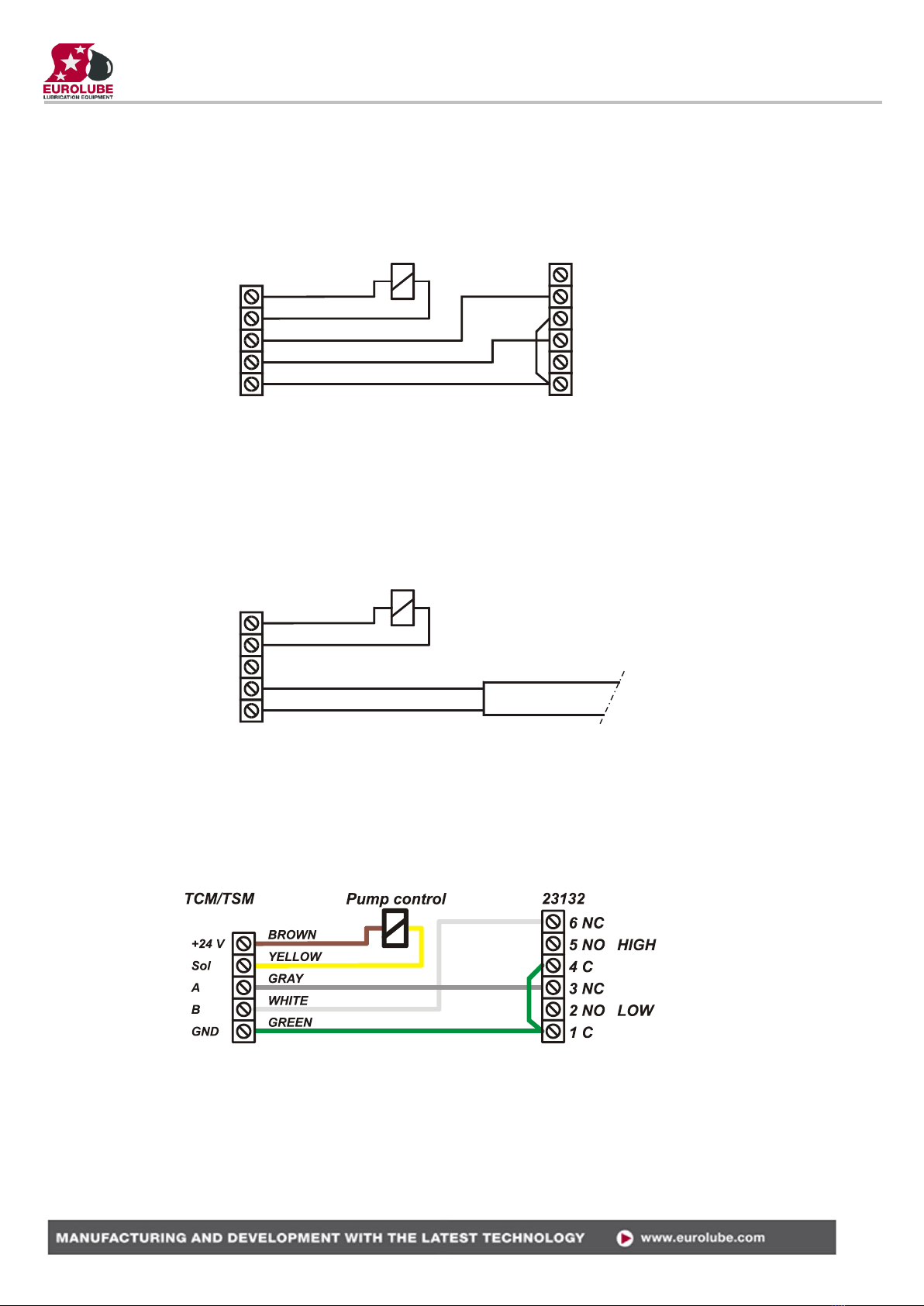
9.3. Waste oil tank, 53132 (2-levels)
To achieve a proper function, that is the pump stops if the physical tank is full or if the sensor is disconnected, the
following connection should be made. Colours are if you use control cable 53412.
The TCM port should be set to control the appropriate PC tank in relation to the physical tank. Correct TankType,
TCMAddress and TCMPort should be set using with WinDB Manager
MASK = 13, TankType = 11?
Solenoid valveTCM 23138
LOW
HIGH
1 C
2 NO
3 NC
4 C
5 NO
6 NC
+24 V
A
GND
B
Sol
Solenoid valveTCM
Blue
Brown 23171
+24 V
A
GND
B
Sol
LUBE-MASTER R10
17(20)
9.4. One TCM port controls a number of pumps
It is possible to control several pumps with only one solenoid valve, that is all pumps starts if one dispense point is
opened. To do this the solenoid valve is connected between +24V and Sol of a TCM port. The port is set to a tank
that does not exist in the PC database and the Mask is set to 0.
For all PC tanks that should be controlled by this solenoid valve the TCMAddress and TCMPort should be set to
this port. Using the WinDB Manager does this.
If this method is used of coarse no level sensor can be used.
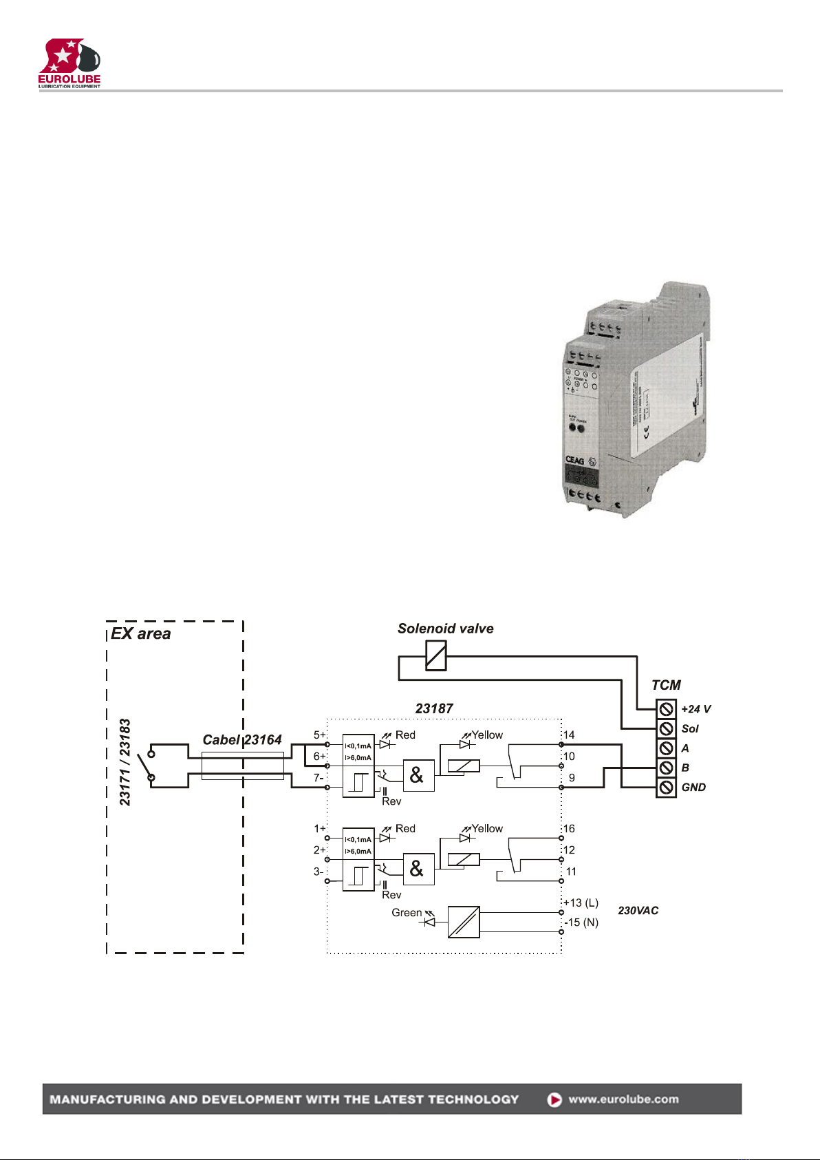
10. EX-barrier 53187 for discrete level sensors.
An EX-barrier is needed between the level sensor and the tank module if the
liquid is classed as flammable. For this purpose the EX-barrier 53178 and a
special EX approved cable 53164 can be used.
The EX-barrier, the solenoid valve that controls the air to the pump and the tank
module should be placed outside the EX-classed area. The EX approved cable
should be used to connect the level sensor on the tank inside the EX-classed area
with the EX-barrier outside the EX-classed area.
Connecting a fresh oil tank 53171/53183 (1-Level).
To achieve a proper function, that is the pump starts only if there are enough oil
in the tank, a dispense point is open and the sensor works properly, the
following connection should be made.
The TCM port should be set to control the appropriate PC tank in relation to the
physical tank.
Correct TankType, TCMAddress and TCMPort should be set using with
WinDB Manager
Mask = 4, TankType=01?

LUBE-MASTER R10
18(20)
10.1.Connecting a waste oil tank 53132 (2-Levels)
To achieve a proper function, that is the pump stops if the physical tank is full or if the sensor is disconnected, the
following connection should be made.
The TCM port should be set to control the appropriate PC tank in relation to the physical tank.
Correct TankType, TCMAddress and TCMPort should be set using with WinDB Manager
MASK = 13, TankType = 11?.
11. To connect an analogue sensor
The four analogue inputs on the TCM support any standard industrial 2-lead / 4-20mA / 24VDC sensors. To connect
sensors a 2-pole connector is used.
11.1.Analogue sensor 53417
The submerged pressure based level sensor 23
417 is a robust sensor that can be used with good
accuracy for tanks with a height of 1 –5 meters.
Max height depends on density of fluid. The
measuring resolution for a TCM with a 23 417
sensor is 4 mm for water and about 4.5 mm for
mineral oil.
Connect the red wire to +24VDC and the black
wire to Sense. +24VDC and Sense are printed on
the PCB.
If the sensor cable (6.5 m) is to short to reach the
TCM it can be lengthen using a standard 2-lead
wire with copper area of 0.5 mm2 for each lead.
For this purpose use the by-packed connection
box.
It is not necessary to use the shield to obtain a good signal because the signal is current based. The shield can be
used for protection grounding purposes if needed.
OBSERVE! It is important that the transparent tube is not blocked and that the humidity protection
filter is used. A blocked tube will cause measuring failure. Not using the humidity protection
could cause sensor malfunction due to corrosion caused by condensed water.
LUBE-MASTER R10
19(20)
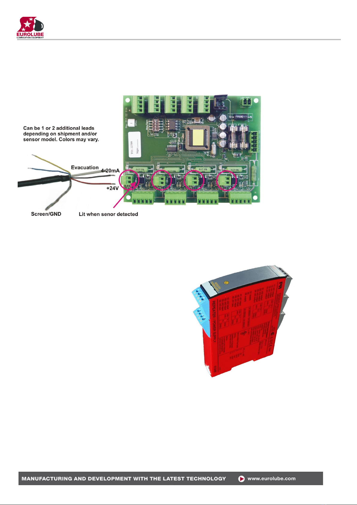
11.2.Connecting an analogue sensor.
The LUBE-Master TCM uses 2-lead 4-20mA 24VDC technique but there are several other techniques that uses
more leads. Because of this the sensor can have more than 2-leads but they are not used.
OBSERVE! Colors may vary between shipments and sensor types so check the sensor manual before
connecting it.
Correct TankType, TCMAddress and TCMPort should be set using with WinDB Manager
MASK = ??, TankType = ??1
12. EX-barrier 53188 for analogue
sensors.
An EX-barrier is needed between the level sensor and
the tank module if the liquid is classed as flammable.
For this purpose the EX-barrier 53188 and a special
EX approved cable p/n 53164 should be used.
The EX-barrier, the solenoid valve that controls the
air to the pump and the tank module should be placed
outside the EX-classed area.
The EX approved cable should be used to connect the
level sensor on the tank inside the EX-classed area
with the EX-barrier outside the EX-classed area.

LUBE-MASTER R10
20(20)
12.1.Connection
The analogue EX-barrier 53188 can handle 2 analogue sensors. Here is shown how to connect an analogue sensor
23 417 to a TCM port using channel 1 of the EX-barrier.
NOTE! The lead colours of the sensor may vary depending on the shipment and make but there are always +,
- and GND/Screen. Known variations are “+” is RED, “-“ is BLACK or BLUE and GND is
YELLOW or SCREEN.
In the connection sample picture the leads of the blue EX-Cable (53164) has for visibility been given
different colours, in the real cable they are black with figures.
13. MPDM PCB mounted in a TCM box
In a small system or at limited space it is possible to mount an additional module PCB in a TCM. In this example a
MPDM board is added. To do this the TCM PCB has to be moved and turned one quarter of a turn. See pictures below:
Make sure that the TCM is disconnected from the mains power supply and the LUBE-
Master network before any work is started. Use a voltmeter to make sure that there
is no power.
To the left is how the standard TCM looks like
inside.
Turn the TCM PCB a quarter of a turn and
place it at the top of the box. Move the plastic
distances to the holes which make it possible
to place the PCB as shown in the picture to the
right. Do not damage the cabling.
Fasten the short plastic distances so the new card can be placed closest to the bottom like
in the picture.
Table of contents
Other Eurolube Control Unit manuals


